Makita HR4002 1-9/16″ Rotary Hammer Instruction Manual
MAKITA HR4002 1-9/16″ Rotary Hammer
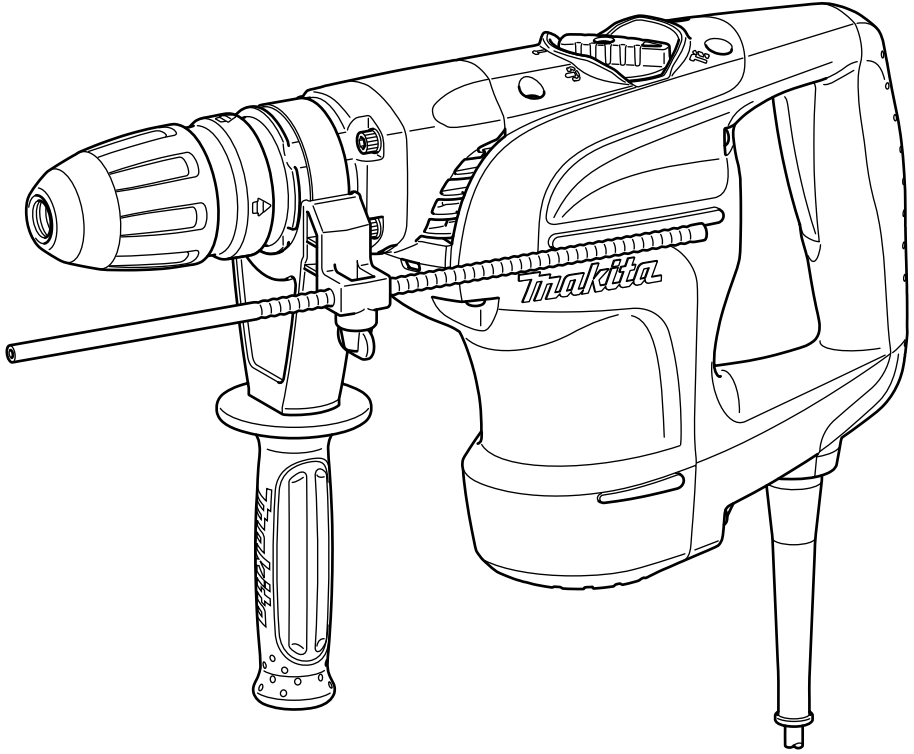

Pictures Illustration


Explanation of general view
- Switch trigger
- Lock button
- Change lever
- Pointer
- Side handle
- Clamp nut
- Side grip
- Bit shank
- Bit grease
- Bit
- Chuck cover
- Depth gauge
- Clamp screw
- Grip base
- Blow-out bulb
SPECIFICATIONS
| Model | HR4002 | |
| Capacities | Carbide-tipped bit | 40 mm |
| Core bit | 105 mm | |
| No load speed (min–1) | 680 | |
| Blows per minute | 2,500 | |
| Overall length | 458 mm | |
| Net weight | 6.6 – 6.8 kg | |
| Safety class | ||

- Due to our continuing program of research and development, the specifications herein are subject to change without notice.
- Specifications may differ from country to country.
- The weight may differ depending on the attachment(s).
The lightest and heaviest combination, according to EPTA-Procedure 01/2014, are shown in the table.
Intended use
The tool is intended for hammer drilling in brick, concrete and stone as well as for chiselling work.
Power supply
The tool should be connected only to a power supply of the same voltage as indicated on the nameplate, and can only be operated on single-phase AC supply. They are double-insulated and can, therefore, also be used from sockets without earth wire.
General power tool safety warnings

ROTARY HAMMER SAFETY WARNINGS
Safety instructions for all operations
- Wear ear protectors. Exposure to noise can cause hearing loss.
- Use auxiliary handle(s), if supplied with the tool.
Loss of control can cause personal injury. - Hold the power tool by insulated gripping surfaces, when performing an operation where the cutting accessory may contact hidden wiring or its own cord. Cutting accessory contacting a “live” wire may make exposed metal parts of the power tool “live” and could give the operator an electric shock.
Safety instructions when using long drill bits with rotary hammers
- Always start drilling at low speed and with the bit tip in contact with the workpiece. At higher speeds, the bit is likely to bend if allowed to rotate freely without contacting the workpiece, resulting in personal injury.
- Apply pressure only in direct line with the bit and do not apply excessive pressure. Bits can bend, causing breakage or loss of control, resulting in personal injury.
ADDITIONAL SAFETY RULES
- Wear a hard hat (safety helmet), safety glasses and/or face shield. Ordinary eye or sun glasses are NOT safety glasses. It is also highly recommended that you wear a dust mask and thickly padded gloves.
- Be sure the bit is secured in place before operation.
- Under normal operation, the tool is designed to produce vibration. The screws can come loose easily, causing a breakdown or accident. Check tightness of screws carefully before operation.
- In cold weather or when the tool has not beenused for a long time, let the tool warm up for a while by operating it under no load. This will loosen up the lubrication. Without proper warmup, hammering operation is difficult.
- Always be sure you have a firm footing. Be sure no one is below when using the tool in high locations.
- Hold the tool firmly with both hands.
- Keep hands away from moving parts.
- Do not leave the tool running. Operate the tool only when hand-held.
- Do not point the tool at any one in the area when operating. The bit could fly out and injure someone seriously.
- Do not touch the bit, parts close to the bit, or workpiece immediately after operation; they may be extremely hot and could burn your skin.
- Some material contains chemicals which may be toxic. Take caution to prevent dust inhalation and skin contact. Follow material supplier safety data.
- Do not touch the power plug with wet hands.
SAVE THESE INSTRUCTIONS.
WARNING:
DO NOT let comfort or familiarity with product(gained from repeated use) replace strict adherence to safety rules for the subject product. MISUSE or failure to follow the safety rules stated in this instruction manual may cause serious personal injury.
FUNCTIONAL DESCRIPTION
CAUTION:
- Always be sure that the tool is switched off and unplugged before adjusting or checking function on the tool.
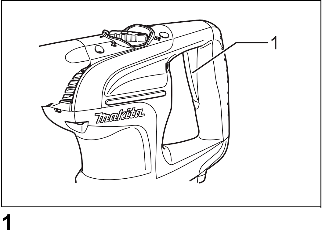
Switch action (Fig. 1)
CAUTION:
- Before plugging in the tool, always check to see that the switch trigger actuates properly and returns to the “OFF” position when released.
To start the tool, simply pull the switch trigger. Release the switch trigger to stop.
Selecting the action mode
Rotation with hammering (Fig. 2)
For drilling in concrete, masonry, etc., depress the lock button and rotate the change lever so that the pointer points to the

Hammering only (Fig. 3)
For chipping, scaling or demolition operations, depress the lock button and rotate the change lever so that the pointer points to the

CAUTION:
- Do not rotate the change lever when the tool is running under load. The tool will be damaged.
- To avoid rapid wear on the mode change mechanism, be sure that the change lever is always positively located in one of the two or three action mode positions
Torque limiter
The torque limiter will actuate when a certain torque level is reached. The motor will disengage from the output shaft. When this happens, the bit will stop turning.
CAUTION:
- As soon as the torque limiter actuates, switch off the tool immediately. This will help prevent premature wear of the tool.
ASSEMBLY
CAUTION:
- Always be sure that the tool is switched off and unplugged before carrying out any work on the tool.
Side handle (accessory) (Fig. 4)
CAUTION:
- Use the side handle only when chipping, scaling or demolishing. Do not use it when drilling in concrete, masonry, etc. The tool cannot be held properly with this side handle when drilling.
The side handle can be swung 360° on the vertical and secured at any desired position. It also secures at eight different positions back and forth on the horizontal. Just loosen the clamp nut to swing the side handle to a desired position. Then tighten the clamp nut securely. (Fig. 5)
Side grip (Fig. 6)
CAUTION:
- Always use the side grip to ensure operating safety when drilling in concrete, masonry, etc.
The side grip swings around to either side, allowing easy handling of the tool in any position. Loosen the side grip by turning it counterclockwise, swing it to the desired position and then tighten it by turning clockwise.
Bit grease (optional accessory)
Coat the bit shank head beforehand with a small amount of bit grease (about 0.5 – 1 g; 0.02 – 0.04 oz.). This chuck lubrication assures smooth action and longer service life.
Installing or removing the bit
Clean the bit shank and apply bit grease before installing the bit. (Fig. 7)
Insert the bit into the tool. Turn the bit and push it in until it engages.
If the bit cannot be pushed in, remove the bit. Pull the chuck cover down a couple of times. Then insert the bit again. Turn the bit and push it in until it engages. (Fig. 8)
After installing, always make sure that the bit is securely held in place by trying to pull it out. To remove the bit, pull the chuck cover down all the way and pull the bit out. (Fig. 9)
Bit angle (when chipping, scaling or demolishing)
The bit can be secured at 12 different angles. To change the bit angle, depress the lock button and rotate the change lever so that the pointer points to the

Depress the lock button and rotate the change lever so that the pointer points to the

Depth gauge (Fig. 12)
The depth gauge is convenient for drilling holes of uniform depth. Insert the depth gauge into the hole in the grip base. Adjust the depth gauge to the desired depth and then tighten the clamp screw to secure the depth gauge.
The depth gauge is convenient for drilling holes of uniform depth. Loosen the clamp screw and adjust the depth gauge to the desired depth. After adjusting, tighten the clamp screw firmly.
NOTE:
- The depth gauge cannot be used at the position where the depth gauge strikes against the tool body.
- The depth gauge cannot be used at the position where the depth gauge strikes against the gear housing/motor housing.
OPERATION
Hammer drilling operation (Fig. 13)
Set the change lever to the
Position the bit at the desired location for the hole, then pull the switch trigger. Do not force the tool. Light pressure gives best results. Keep the tool in position and prevent it from slipping away from the hole.
Do not apply more pressure when the hole becomes clogged with chips or particles. Instead, run the tool at an idle, then remove the bit partially from the hole. By repeating this several times, the hole will be cleaned out and normal drilling may be resumed.

CAUTION:
- When the bit begins to break through concrete or if the bit strikes reinforcing rods embedded in concrete, the tool may react dangerously. Maintain good balance and safe footing while holding the tool firmly with both hands to prevent dangerous reaction.
Blow-out bulb (optional accessory) (Fig. 14)
After drilling the hole, use the blow-out bulb to clean the dust out of the hole.
Chipping/Scaling/Demolition (Fig. 15)
Set the change lever to the
MAINTENANCE
CAUTION:
- Always be sure that the tool is switched off and unplugged before attempting to perform inspection or maintenance.
- Never use gasoline, benzine, thinner, alcohol or the like. Discoloration, deformation or cracks may result.
Lubrication
CAUTION:
- This servicing should be performed by Makita Authorized Service Centers only.
This tool requires no hourly or daily lubrication because it has a grease-packed lubrication system. It should be relubricated regularly. Send the complete tool to Makita Authorized or Factory Service Center for this lubrication service.
To maintain product SAFETY and RELIABILITY, repairs,any other maintenance or adjustment should be performed by Makita Authorized Service Centers, always using Makita replacement parts
OPTIONAL ACCESSORIES
CAUTION:
- These accessories or attachments are recommended for use with your Makita tool specified in this manual. The use of any other accessories or attachments might present a risk of injury to persons. Only use accessory or attachment for its stated purpose.
If you need any assistance for more details regarding these accessories, ask your local Makita Service Center. - SDS-Max Carbide-tipped bits
- SDS-Max bull point
- SDS-Max cold chisel
- SDS-Max scaling chisel
- SDS-Max tile chisel
- SDS-Max clay spade
- Hammer grease
- Bit grease
- Side handle
- Side grip
- Depth gauge
- Blow-out bulb
- Safety goggles
- Carrying case
NOTE:
- Some items in the list may be included in the tool package as standard accessories. They may differ from country to country.
Noise
The typical A-weighted noise level determined according to EN62841-2-6:
Sound pressure level (LpA): 92 dB (A)
Sound power level (LwA): 103 dB (A)
Uncertainty (K): 3 dB (A)
NOTE:
- The declared noise emission value(s) has been measured in accordance with a standard test method and may be used for comparing one tool with another.
- The declared noise emission value(s) may also be used in a preliminary assessment of exposure.
WARNING:
- Wear ear protection.
- The noise emission during actual use of the power tool can differ from the declared value(s) depending on the ways in which the tool is used especially what kind of workpiece is processed.
- Be sure to identify safety measures to protect the operator that are based on an estimation of exposure in the actual conditions of use (taking account of all parts of the operating cycle such as the times when the tool is switched off and when it is running idle in addition to the trigger time).
Vibration
The vibration total value (tri-axial vector sum) determined according to EN62841-2-6:
Work mode: chiselling function with side grip
Vibration emission (ah,CHeq): 11.1 m/s2
Uncertainty (K): 1.6 m/s2
Work mode: hammer drilling into concrete
Vibration emission (ah,HD): 12.3 m/s2
Uncertainty (K): 1.5 m/s2
NOTE:
- The declared vibration total value(s) has been measured in accordance with a standard test method and may be used for comparing one tool with another.
- The declared vibration total value(s) may also be used in a preliminary assessment of exposure.
WARNING:
- The vibration emission during actual use of the power tool can differ from the declared value(s) depending on the ways in which the tool is used especially what kind of workpiece is processed.
- Be sure to identify safety measures to protect the operator that are based on an estimation of exposure in the actual conditions of use (taking account of all parts of the operating cycle such as the times when the tool is switched off and when it is running idle in addition to the trigger time).
EC DECLARATION OF CONFORMITY
For European countries only
The EC declaration of conformity is included as Annex A to this instruction manual.
