Pioneer ND-BC8 Universal Rear-View Camera Owner’s Manual


Owner’s Manual
UNIVERSAL REAR-VIEW CAMERA
ND-BC8
PIONEER ELECTRONICS (USA) INC.
P.O. Box 1540, Long Beach, California 90801-1540, U.S.A.
TEL: (800) 421-1404
Installation
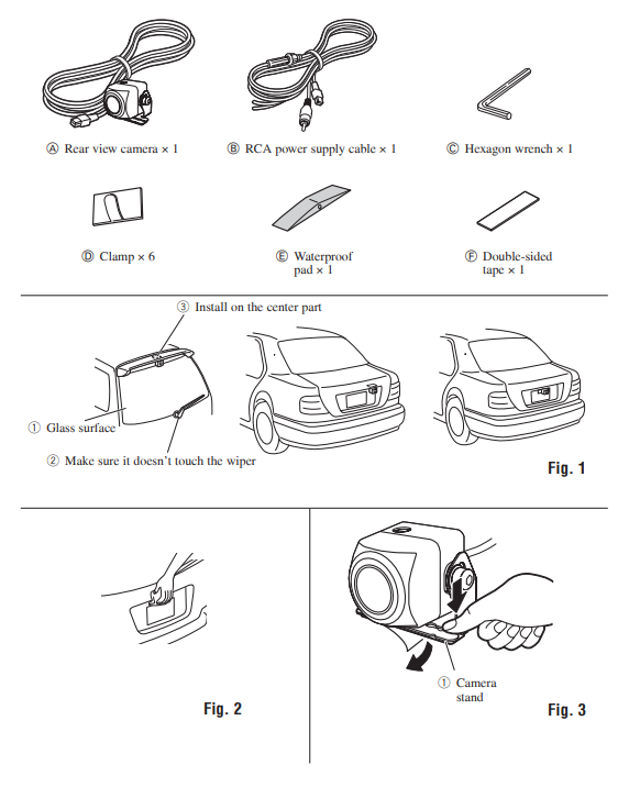
Parts supplied
A Rearview camera × 1
B RCA power supply cable × 1
C Hexagon wrench × 1
D Clamp × 6
E Waterproof pad × 1
F Double-sided tape × 1
Installation example (Fig. 1)
- Glass surface
- Make sure it doesn’t touch the wiper
- Install on the center part
Installation procedure
Notes:
- Before making a final installation of the unit, temporarily connect the wiring to confirm that the connections are correct and the system works properly.
- Use only the parts included with the unit to ensure proper installation. The use of unauthorized parts can cause malfunctions.
- Consult with your nearest dealer if installation requires the drilling of holes or other modifications of the vehicle.
- Install the unit where it does not get in the driver’s way and cannot injure the passenger if there is a sudden stop, like an emergency stop.
- When mounting this unit, make sure none of the leads are trapped between this unit and the surrounding metalwork or fittings.
- Before drilling any mounting holes always check behind where you want to drill the holes. Do not drill into the gas line, brake line, electrical wiring or other important parts.
- If this unit is installed in the passenger compartment, anchor it securely so it does not break free while the car is moving, and cause injury or an accident.
- If the wiring of this unit is located under a front seat, make sure it does not obstruct seat movement. Route all leads and cords carefully around the sliding mechanism so they do not get caught or pinched in the mechanism and cause a short circuit.
- Install the unit near the center of the car.
- Locate in the position you want to install the rearview camera. Adjust the angle of the rearview camera, and install it so that the camera doesn’t touch the car.
- When sticking to a glass surface, stick it on in a position that assures the camera doesn’t touch the rear window.
- Install so that it does not obstruct the rear field of view.
- Install so that it does not protrude from the side of the car.
- Do not perform installation in rain or fog.
- When humidity is high, dry the surface to which the unit is to be attached before installing. Moisture on the attachment surface reduces adhesive strength which may lead to the unit coming off.
- If the temperature of the attachment surface is low, warm it with a hairdryer of other means before installing it to improve adhesive strength.
- Do not attach the camera stand to areas on the car body treated with fluorocarbon resin, or glass. This may result in the rearview camera falling off.
- During the 24-hour period after installing:
– Do not apply water to the unit.
– Do not expose the unit to rain.
– Do not subject the camera to unnecessary force. - Thoroughly clean where the tape is used for sticking on the unit.
- Clean the surface on which the rearview
camera is to be installed.
(Fig. 2)
Use a cloth or other item to wipe oil, wax, dust, and any other dirt from the installation surface. - Peel off the sheet on the back of the
camera stand and stick it on. (Fig. 3,
Fig. 4, Fig. 5)
Press the camera stand with your fingers to stick it to the installation surface. Touching the adhesive surface or sticking the unit on a second time reduces adhesive power
which may result in the unit coming off.
1 Camera stand
2 Top
3 Mark
4 Bottom
5 Make sure to install the rearview camera so that the mark is located on top of the camera.
6 Be sure not to hide any part of the characters on the license plate when attaching the camera. - Adjust the angle so that the bumper
or rear edge of the car is displayed
at the bottom of the TV screen.
(Fig. 6, Fig. 7, Fig. 8)
1 Hexagon wrench
2 Bumper or rear edge of the car


This device complies with part 15 of the FCC Rules.
Operation is subject to the following two conditions:
(1) This device may not cause harmful interference, and
(2) this device must accept any interference received, including interference that may cause undesired operation.
Information to User
Alteration or modifications carried out without appropriate authorization may invalidate the user’s right to operate the equipment.
Note:
This equipment has been tested and found to comply with the limits for a Class B digital device, pursuant to Part 15 of the FCC Rules. These limits are designed to provide reasonable protection against harmful interference in a residential installation.
This equipment generates, uses, and can radiate radio frequency energy and, if not installed and used in accordance with the instructions, may cause harmful interference to radio communications. However, there is no guarantee that interference will not occur in a particular installation. If this equipment does cause harmful interference to radio or television reception, which can be determined by turning the equipment off and on, the user is encouraged to try to correct the interference by one or more of the following
measures:
- Reorient or relocate the receiving antenna.
- Increase the separation between the equipment and receiver.
- Connect the equipment into an outlet on a circuit different from that to which the receiver is connected.
- Consult the dealer or an experienced radio/TV technician for help.

Private households in the member states of the EU, in Switzerland and Norway may return their used electronic products free of charge to designated collection facilities or to a retailer (if you purchase a similar new one).
For countries not mentioned above, please contact your local authorities for the correct method of disposal. By doing so you will ensure that your disposed product undergoes the necessary treatment, recovery, and recycling and thus prevent potential negative effects on the environment and human health.
WARNING:
This product contains chemicals known to the State of California and other governmental entities to cause cancer and birth defects or other reproductive harm.
Wash hands after handling.
IMPORTANT SAFEGUARDS
- Installation and wiring of this product require specialist skills and experience.
To assure your safety, please request a specialist technician to install the unit. - Do not attempt to heat the surface of the camera lens or camera lens itself with a lighter and so on when they have become frozen. This can cause a malfunction.
- This product is a rearview camera for checking the view at the rear of a car.
A rearview camera is a camera that provides symmetrical images in the same way as rear and side-view mirrors. - Connection to a TV with an RCA video input is possible, but confirm whether the TV you use has a reverse gear connection function.
- This product is designed to supplement the driver’s rearview, but the camera images do not show all dangers and obstacles. Be sure to look behind you when reversing to confirm the view.
- This product features a wide-angle lens, so the near view is wide and the far view is narrow, which may create a false sense of distance. Be sure to look behind you when reversing to confirm the view.
- Do not wash your car with an automatic car wash or high-pressure water as it may result in water entering the camera or the camera falling off.
- Check camera stand installation before driving.
– Are the screws loose?
– Is the camera stand firmly secured?
– If the rearview camera comes loose while you are driving it may cause an accident. - This product by itself does not display guidelines.
Connection
Notes:
- This unit is for vehicles with a 12-volt battery and negative grounding. Before installing it in a recreational vehicle, truck, or bus, check the battery voltage.
- To avoid shorts in the electrical system, be sure to disconnect the battery cable before beginning installation.
- Refer to the owner’s manual for details on connecting the other units, then make connections correctly.
- Secure the wiring with cable clamps or adhesive tape. To protect the wiring, wrap adhesive tape around them where they lie against metal parts.
- Route and secure all wiring so it cannot touch any moving parts, such as the gear shift, parking brake, and seat rails. Do not route wiring in places that get hot, such as near the heater outlet. If the insulation of the wiring melts or gets torn, there is a danger of the wiring short-circuiting to the vehicle body.
- Do not shorten any leads.
- Never feed power to other equipment by cutting the insulation of the power supply lead of the unit and tapping into the lead.
The current capacity of the lead will be exceeded, causing overheating. - When replacing the fuse, be sure to only use a fuse of the rating prescribed on the fuse holder.
- To minimize noise locate the TV antenna cable, radio antenna cable, and RCA power supply cable as far away from each other as possible.
- Connection to a TV with an RCA video input is possible, but confirm whether the TV you use has a reverse gear connection function.
- If this unit is installed in a vehicle that does not have an ACC (accessory) position on the ignition switch, the red lead of the unit should be connected to a terminal coupled
with the ignition switch ON/OFF operations. If this is not done, the vehicle battery may be drained when you are away from the vehicle for several hours.

- Cords for this product and those for other products may be different colors even if they have the same function. When connecting this product to another product, refer to
the supplied manuals of both products and connect cords that have the same function.
Connection sample (Fig. 9)
- Rearview camera
Video input jack
Connect to camera input jack (REAR
VIEW CAMERA IN). - RCA pin
Accessory power supply
To electric terminal controlled by ignition switch (12 V DC) ON/OFF. - Red
- Fuse (1 A)
Ground
To vehicle (metal) body. - Black
Cord installation (Fig. 10)
- Clamps
- Rearview camera
- RCA power supply cable
- Product with a video input jack (Hideaway unit etc.)
- Made with a rasp etc.
- Scuff plate
- Clamp
- Waterproof pad
Attach the waterproof pad using double-sided tape.
Cord installation points (Fig. 11, Fig. 12)
- When pulling the cord out of the car, pull from the outer side of the hatch harness cover and hinge. (Fig. 11)
1 Pull out from here
2 Hinge
3 Harness cover
4 Rearview camera
5 Hatch - When the rearview camera cord cannot be pulled out from the lower side, bend the cord into a U shape in front of the waterproof pad, making sure that rainwater cannot enter the car by running down the cord. (Fig. 12)
1 Clamp
2 Waterproof pad
3 Rubber packing
4 Make a U-shaped loop in the lead outside the rubber packing to prevent rainwater from flowing along the lead into the interior of the vehicle.
Attach the waterproof pad using double-sided tape.


After cord installation
Open and close the hatch door slowly to confirm that the cord is not rubbing against the rim of the door.
Specifications
Power source ……………………………………. 14.4 V DC (10.8 V to 15.1 V allowable)
Grounding system ………………………… Negative type
Max. current consumption …………… 100 mA or less
Output video ………………………………… Mirror image (for rearview confirmation)
Sensor ……………………. 1/4-inch color CMOS sensor
No. of pixels ……………… effective no. of pixels roughly 310 000
Lens ……………………………………………….. Wide-angle, focal length f = 1.12 mm, F value 2.3
Angle of view ……………… Horizontal: approx. 129 º Vertical: approx. 105 º
IR cutoff filter (special filter for vehicle mounting) ………………………………………………………… Provided
Iris system …………………………………… Electronic iris
Scanning system …………………………………. Interlace
Synchronizing system ……. Internal synchronization
Signal-to-noise ratio …………………….. 40 dB or more (at the recommended intensity of illumination)
Horizontal resolution ………… Approx. 350 TV lines
Illumination range …. Approx. 0.9 lux to 100 000 lux
Image output …….. NTSC compatible 1 Vp-p (75 Ω)
Operation temperature range ……… –30 ºC to +70 ºC –22 ºF to +158 ºF
Storage temperature range ………… –40 ºC to +85 ºC –40 ºF to +185 ºF
Dimensions (W × H × D)………………… 23.8 mm × 23.8 mm × 25.5 mm (7/8 in. × 7/8 in. × 1 in.)
Weight ………………………………………….186 g (0.4 lbs) (including the cable)Length
Rearview camera cable ………. 3 m (9 ft. 10 in.)
RCA power supply cable …… 7 m (22 ft. 12 in.)
Note:
Specifications and the design are subject to possible modification without prior notice due to improvements.

© 2015-2016 PIONEER CORPORATION.
All rights reserved.