Makita DCC501 18V Brushless 125mm Cordless Cutter Instruction Manual


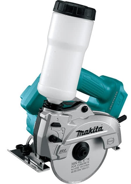
Makita DCC501 18V Brushless 125mm Cordless Cutter

HOW TO USE


SPECIFICATIONS
| Model: | DCC501 | |
| Wheel diameter | 125 mm | |
| Max. wheel thickness | 2.2 mm | |
| Max. cutting capacities | 0° bevel angle | 40 mm |
| 45° bevel angle | 27 mm | |
| Rated speed (n) | 8,800 min-1 | |
| Overall length | 283 mm *1 | |
| Rated voltage | D.C. 18 V | |
| Net weight | 2.7 – 3.0 kg | |
With battery cartridge (BL1860B)
- Due to our continuing program of research and development, the specifications herein are subject to change without notice.
- Specifications and battery cartridges may differ from country to country.
- The weight may differ depending on the attachment(s), including the battery cartridge. The lightest and heaviest combinations, according to EPTA-Procedure 01/2014, are shown in the table.
Applicable battery cartridge and charger
| Battery cartridge | BL1815N / BL1820B / BL1830B / BL1840B / BL1850B / BL1860B |
| Charger | DC18RC / DC18RD / DC18RE / DC18SD / DC18SE / DC18SF / DC18SH |
Some of the battery cartridges and chargers listed above may not be available depending on your region of residence.
WARNING: Only use the battery cartridges and chargers listed above. Use of any other battery cartridges and chargers may cause injury and/or fire.
Intended use
The tool is intended for cutting in brick and concrete with a diamond wheel and water.
Noise
- The typical A-weighted noise level determined according to EN60745-2-22:
- Sound pressure level (LpA) : 96 dB(A)
- Sound power level (LWA) : 107 dB (A)
- Uncertainty (K) : 3 dB(A)
Note
- The declared noise emission value(s) has been measured in accordance with a standard test method and may be used for comparing one tool with another.
- The declared noise emission value(s) may also be used in a preliminary assessment of exposure.
WARNING
- Wear ear protection
- The noise emission during actual use of the power tool can differ from the declared value(s) depending on the ways in which the tool is used especially what kind of workpiece is processed.
- Be sure to identify safety measures to protect the operator that is based on an estimation of exposure in the actual conditions of use (taking account of all parts of the operating cycle such as the times when the tool is switched off and when it is running idle in addition to the trigger time).
- The vibration emission during actual use of the power tool can differ from the declared value(s) depending on the ways in which the tool is used especially what kind of workpiece is processed.
- Be sure to identify safety measures to protect the operator that is based on an estimation of exposure in the actual conditions of use (taking account of all parts of the operating cycle such as the times when the tool is switched off and when it is running idle in addition to the trigger time).
Vibration
- The vibration total value (tri-axial vector sum) determined according to EN60745-2-22:
- Work mode: concrete cutting
- Vibration emission (ah) : 4.0 m/s2
- Uncertainty (K) : 1.5 m/s2
The declared vibration total value(s) has been measured in accordance with a standard test method and may be used for comparing one tool with another. NOTE: The declared vibration total value(s) may also be used in a preliminary assessment of exposure.
EC Declaration of Conformity
For European countries only
The EC declaration of conformity is included as Annex A to this instruction manual.
SAFETY WARNINGS
General power tool safety warnings
Save all warnings and instructions for future reference. The term “power tool” in the warnings refers to your mains-operated (corded) power tool or battery-operated (cordless) power tool.
Cutter safety warnings
- The guard provided with the tool must be securely attached to the power tool and positioned for maximum safety, so the least amount of wheel is exposed to the operator. Position yourself and bystanders away from the plane of the rotating wheel. The guard helps to protect the operator from broken wheel fragments and accidental contact with the wheel. 2. Use only diamond cut-off wheels for your power tool. Just because an accessory can be attached to your power tool, it does not assure safe operation.
- The rated speed of the accessory must be at least equal to the maximum speed marked on the power tool. Accessories running faster than their rated speed can break and fly apart. 4. Wheels must be used only for recommended applications. For example: do not grind with the side of the cut-off wheel. Abrasive cut-off wheels are intended for peripheral grinding, side forces applied to these wheels may cause them to shatter.
- Always use undamaged wheel flanges that are of the correct diameter for your selected wheel. Proper wheel flanges support the wheel thus reducing the possibility of wheel breakage.
- The outside diameter and the thickness of your accessory must be within the capacity rating of your power tool. Incorrectly sized accessories cannot be adequately guarded or controlled.
- The arbor size of wheels and flanges must properly fit the spindle of the power tool. Wheels and flanges with arbor holes that do not match the mounting hardware of the power tool will run out of balance, vibrate excessively, and may cause loss of control.
- Do not use damaged wheels. Before each use, inspect the wheels for chips and cracks. If a power tool or wheel is dropped, inspect for damage or install an undamaged wheel. After inspecting and installing the wheel, position yourself and bystanders away from the plane of the rotating wheel and run the power tool at maximum no-load speed for one minute. Damaged wheels will normally break apart during this test time.
- Wear personal protective equipment. Depending on the application, use a face shield, safety goggles, or safety glasses. As appropriate, wear a dust mask, hearing protectors, gloves, and a shop apron capable of stopping small abrasive or workpiece fragments. The eye protection must be capable of stopping flying debris generated by various operations. The dust mask or respirator must be capable of filtrating particles generated by your operation. Prolonged exposure to high-intensity noise may cause hearing loss.
- Keep bystanders a safe distance away from the work area. Anyone entering the work area must wear personal protective equipment. Fragments of a workpiece or of a broken wheel may fly away and cause injury beyond the immediate area of operation.
- Hold the power tool by insulated gripping surfaces only, when performing an operation where the cutting accessory may contact hidden wiring. Cutting accessory contacting a “live” wire may make exposed metal parts of the power tool “live” and could give the operator an electric shock.
- Never lay the power tool down until the accessory has come to a complete stop. The spinning wheel may grab the surface and pull the power tool out of your control.
- Do not run the power tool while carrying it at your side. Accidental contact with the spinning accessory could snag your clothing, pulling the accessory into your body.
- Regularly clean the power tool’s air vents. The motorʼs fan will draw the dust inside the housing and excessive accumulation of powdered metal may cause electrical hazards.
- Do not operate the power tool near flammable
materials. Sparks could ignite these materials.
Kickback and related warnings
- Kickback is a sudden reaction to a pinched or snagged rotating wheel. Pinching or snagging causes rapid stalling of the rotating wheel which in turn causes the uncontrolled power tool to be forced in the direction opposite of the wheel’s rotation at the point of the binding. For example, if an abrasive wheel is snagged or pinched by the workpiece, the edge of the wheel that is entering into the pinch point can dig into the surface of the material causing the wheel to climb out or kick out. The wheel may either jump toward or away from the operator, depending on direction of the wheel’s movement at the point of pinching. Abrasive wheels may also break under these conditions. Kickback is the result of power tool misuse and/or incorrect operating procedures or conditions and can be avoided by taking proper precautions as given below.
- Maintain a firm grip on the power tool and position your body and arm to allow you to resist kickback forces. Always use auxiliary handle, if provided, for maximum control over kickback or torque reaction during start-up. The operator can control torque reactions or kickback forces, if proper precautions are taken.
- Never place your hand near the rotating accessory. Accessory may kickback over your hand.
- Do not position your body in line with the rotating wheel. Kickback will propel the tool in direction opposite to the wheel’s movement at the point of snagging.
- Use special care when working corners, sharp edges etc. Avoid bouncing and snagging the accessory. Corners, sharp edges or bouncing have a tendency to snag the rotating accessory and cause loss of control or kickback.
- Do not attach a saw chain, woodcarving blade, segmented diamond wheel with a peripheral gap greater than 10 mm or toothed saw blade. Such blades create frequent kickback and loss of control.
- Do not “jam” the wheel or apply excessive pressure. Do not attempt to make an excessive depth of cut. Overstressing the wheel increases the loading and susceptibility to twisting or binding of the wheel in the cut and the possibility of kickback or wheel breakage.
- When wheel is binding or when interrupting a cut for any reason, switch off the power tool and hold the power tool motionless until the wheel comes to a complete stop. Never attempt to remove the wheel from the cut while the wheel is in motion otherwise kickback may occur. Investigate and take corrective action to eliminate the cause of wheel binding.
- Do not restart the cutting operation in the workpiece. Let the wheel reach full speed and carefully re-enter the cut. The wheel may bind, walk up or kickback if the power tool is restarted in the workpiece.
- Support panels or any oversized workpiece to minimize the risk of wheel pinching and kickback. Large workpieces tend to sag under their own weight. Supports must be placed under the workpiece near the line of cut and near the edge of the workpiece on both sides of the wheel.
- Use extra caution when making a “pocket cut” into existing walls or other blind areas. The protruding wheel may cut gas or water pipes, electrical wiring or objects that can cause kickback.
- Before using a segmented diamond wheel, make sure that the diamond wheel has the peripheral gap between segments of 10 mm or less, only with a negative rake angle.
Additional Safety Warnings
- Never attempt to cut with the tool held upside down in a vise. This can lead to serious accidents, because it is extremely dangerous.
- Some material contains chemicals which may be toxic. Take caution to prevent dust inhalation and skin contact. Follow material supplier safety data.
- Store wheels as per manufacturer recommendations. Improper storage may damage the wheels.
SAVE THESE INSTRUCTIONS
Important safety instructions for battery cartridge
Before using battery cartridge, read all instructions and cautionary markings on
- Battery charger,
- Battery, and
- Product using battery.
- Do not disassemble or tamper with the battery cartridge. It may result in a fire, excessive heat, or explosion.
- If operating time has become excessively shorter, stop operating immediately. It may result in a risk of overheating, possible burns and even an explosion.
- If electrolyte gets into your eyes, rinse them out with clear water and seek medical attention right away. It may result in loss of your eyesight.
- Do not short the battery cartridge:
- Do not touch the terminals with any conductive material.
- Avoid storing battery cartridge in a container with other metal objects such as nails, coins, etc.
- Do not expose battery cartridge to water or rain.
- A battery short can cause a large current flow, overheating, possible burns and even a breakdown.
- Do not store and use the tool and battery cartridge in locations where the temperature may reach or exceed 50 °C (122 °F).
- Do not incinerate the battery cartridge even if it is severely damaged or is completely worn out. The battery cartridge can explode in a fire.
- Do not nail, cut, crush, throw, drop the battery cartridge, or hit against a hard object to the battery cartridge. Such conduct may result in a fire, excessive heat, or explosion.
- Do not use a damaged battery The contained lithium-ion batteries are subject to the Dangerous Goods Legislation requirements. For commercial transports e.g. by third parties, forwarding agents, special requirement on packaging and labeling must be observed.
- For preparation of the item being shipped, consulting an expert for hazardous material is required. Please also observe possibly more detailed national regulations.
- Tape or mask off open contacts and pack up the battery in such a manner that it cannot move around in the packaging.
- When disposing the battery cartridge, remove it from the tool and dispose of it in a safe place. Follow your local regulations relating to disposal of battery.
- Use the batteries only with the products specified by Makita. Installing the batteries to non-compliant products may result in a fire, excessive heat, explosion, or leak of electrolyte.
- If the tool is not used for a long period of time, the battery must be removed from the tool.
- During and after use, the battery cartridge may take on heat which can cause burns or low temperature burns. Pay attention to the handling of hot battery cartridges.
- Do not touch the terminal of the tool immediately after use as it may get hot enough to cause burns.
- Do not allow chips, dust, or soil stuck into theterminals, holes, and grooves of the battery cartridge. It may result in poor performance or breakdown of the tool or battery cartridge.
- Unless the tool supports the use nea high-voltage electrical power lines, do not use the battery cartridge near high-voltage electrical power lines. It may result in a malfunction or breakdown of the tool or battery cartridge.
- Keep the battery away from children.
Tips for maintaining maximum battery life
Charge the battery cartridge before completely discharged. Always stop tool operation and charge the battery cartridge when you notice less tool power.
- Never recharge a fully charged battery cartridge. Overcharging shortens the battery service life.
- Charge the battery cartridge at room temperature at 10 °C – 40 °C (50 °F – 104 °F). Let a hot battery cartridge cool down before charging it.
- When not using the battery cartridge, remove it from the tool or the charger.
- Charge the battery cartridge if you do not use it for a long period (more than six months).
Important safety instructions for the wireless unit
- Do not disassemble or tamper with the wireless unit.
- Keep the wireless unit away from young children. If accidentally swallowed, seek medical attention immediately.
- Use the wireless unit only with Makita tools.
- Do not expose the wireless unit to rain or wet conditions.
- Do not use the wireless unit in places where the temperature exceeds 50°C (122°F).
- Do not operate the wireless unit in places where medical instruments, such as heart pace makers are nearby.
- Do not operate the wireless unit in places whereautomated devices are nearby. If operated, automated devices may develop malfunction or error.
- Do not operate the wireless unit in places under high temperature or places where static electricity or electrical noise could be generated.
- The wireless unit can produce electromagnetic fields (EMF) but they are not harmful to the user.
- The wireless unit is an accurate instrument. Be careful not to drop or strike the wireless unit.
- Avoid touching the terminal of the wireless unit with bare hands or metallic materials.
- Always remove the battery on the product when installing the wireless unit into it.
- When opening the lid of the slot, avoid the place where dust and water may come into the slot. Always keep the inlet of the slot clean.
- Always insert the wireless unit in the correct direction.
- Do not press the wireless activation button on the wireless unit too hard and/or press thebutton with an object with a sharp edge.
- Always close the lid of the slot when operating.
- Do not remove the wireless unit from the slot while the power is being supplied to the tool. Doing so may cause a malfunction of the wireless unit.
- Do not remove the sticker on the wireless unit.
- Do not put any sticker on the wireless unit.
- Do not leave the wireless unit in a place where static electricity or electrical noise could be generated.
- Do not leave the wireless unit in a place subject to high heat, such as a car sitting in the sun.
- Do not leave the wireless unit in a dusty or powdery place or in a place corrosive gas could be generated.
- Sudden change of the temperature may bedew the wireless unit. Do not use the wireless unit until the dew is completely dried.
- When cleaning the wireless unit, gently wipe with a dry soft cloth. Do not use benzine, thinner, conductive grease or the like.
- When storing the wireless unit, keep it in the supplied case or a static-free container.
- Do not insert any devices other than Makita wireless unit into the slot on the tool.
- Do not use the tool with the lid of the slot damaged. Water, dust, and dirt coming into the slot may cause malfunction.
- Do not pull and/or twist the lid of the slot more than necessary. Restore the lid if it comes off from the tool.
- Replace the lid of the slot if it is lost or damaged.
FUNCTIONAL DESCRIPTION
Installing or removing the battery cartridge
- Red indicator
- Button
- Battery cartridge
To remove the battery cartridge, slide it from the tool while sliding the button on the front of the cartridge. To install the battery cartridge, align the tongue on the battery cartridge with the groove in the housing and slip it into place. Insert it all the way until it locks in place with a little click. If you can see the red indicator on the upper side of the button, it is not locked completely.
Indicating the remaining battery capacity
Only for battery cartridges with the indicator Indicator lamps Check button Press the check button on the battery cartridge to indicate the remaining battery capacity. The indicator lamps light up for a few seconds.

- Tool/battery protection system
- The tool is equipped with a tool/battery protection system. This system automatically cuts off power to the motor to extend tool and battery life. The tool will automatically stop during operation if the tool or battery is placed under one of the following conditions.
- Overload protection
When the tool/battery is operated in a manner that causes it to draw an abnormally high current, the tool automatically stops. In this situation, turn the tool off and stop the application that caused the tool to become overloaded. Then turn the tool on to restart. - Overheat protection
When the tool/battery is overheated, the tool stops automatically and the operation lamp will blink. In this situation, let the tool cool down before turning the tool on again. - Over-discharge protection
When the battery capacity becomes low, the tool stops automatically. If the tool does not run along with the switch operation, remove the battery from the tool and charge it. - Adjusting the depth of cut
- Loosen the lever on the depth guide and move the base up or down. At the desired depth of cut, secure the base by tightening the lever. For cleaner, safer cuts set cut depth so that the diamond wheel projects 2 mm or less below the workpiece. Using proper cut depth helps to reduce the potential for dangerous KICKBACKS which can cause personal injury.
- Bevel cutting
- Loosen the clamping screw on the bevel scale plate on the front of the base. Set for the desired angle (0° – 45°) by tilting accordingly, then tighten the clamping screw securely
Sighting
For straight cutting
Align the side edge of the base with your intended cutting line on the workpiece.
- Side edge of the base
- Cutting line
For 45° bevel cutting
Align the inner edge of the guide notch in the base with your intended cutting line on the workpiece.
- The inner edge of the guide notch
- Cutting line
Switch action
- NEVER use the tool if it runs when you simply pull the switch trigger without pressing the lock-off button. A switch in need of repair may result in unintentional operation and serious personal injury. Return the tool to a Makita service center for proper repairs BEFORE further usage.
- NEVER defeat the lock-off button by taping it down or some other means. A switch with a negated lock-off button may result in unintentional operation and serious personal injury.
- Before installing the battery cartridge into the tool, always check to see that the switch trigger actuates properly and returns to the “OFF” position when released.
- Do not pull the switch trigger hard without pressing the lock-off button. This can cause switch breakage.
- The tool starts to brake the diamond wheel rotation immediately after you release the switch trigger. Hold the tool firmly to respond to the reaction of the brake when releasing the switch trigger. A sudden reaction can drop the tool off your hand and can cause a personal injury
- To prevent the switch trigger from being accidentally pulled, a lock-off button is provided. To start the tool, press the lock-off button and pull the switch trigger. Release the switch trigger to stop.
Shaft lock
Press the shaft lock to prevent spindle rotation when installing or removing a diamond wheel.
Lighting the lamp
- Do not look in the light or see the source of light directly.
- To turn on the operation lamp, press and hold the lock-off button and pull the switch trigger.
- The lamp goes out 10 seconds after releasing the switch trigger.
- Use a dry cloth to wipe the dirt off the lens of the lamp. Be careful not to scratch the lens or lamp, or it may lower the illumination.
Overload alert
If the tool is operated with excessive load, the operation lamp will blink. In this situation, reduce the load on the tool, and the lamp stops blinking.
Electronic function
- Electric brake
- This tool is equipped with an electric blade brake. If the tool consistently fails to quickly cease to function after the switch trigger is released, have the tool serviced at a Makita service center.
- Automatic speed change function
- This tool has “high-speed mode” and “high torque mode”. The tool automatically changes the operation mode depending on the workload. When the workload is low, the tool will run in the “high-speed mode” for quicker cutting operation. When the workload is high, the tool will run in the “high torque mode” for powerful cutting operation.
- Soft start feature
- This function allows the smooth start-up of the tool by limiting the start-up torque.
ASSEMBLY
- Always be sure that the tool is switched off and the battery cartridge is removed before carrying out any work on the tool.
- Hex wrench storage
- When not in use, store the hex wrench as shown in the figure to keep it from being lost.
- Removing and installing diamond wheel
- Use only the Makita hex wrench supplied to remove and install a diamond wheel. When installing a diamond wheel, be sure to tighten the bolt securely. Always install a diamond wheel so that the arrows on the diamond wheel point in the same direction as the arrows on the wheel cover and gear housing. Otherwise, if the wheel rotates in reverse, it may cause personal injury.
- To remove the diamond wheel, press the shaft lock fully so that the diamond wheel cannot revolve and use the hex wrench to loosen the hex bolt clockwise. Then remove the hex bolt, outer flange, and diamond wheel.
- If the inner flange is removed, install it on the spindle with its wheel mounting part facing the diamond wheel.
- To install a diamond wheel, follow the removal procedure in reverse. Make sure the diamond wheel is installed so that the arrows on the wheel point in the same direction as the arrows on the wheel cover and gear housing.
- Water supply tank
- When filling the tank with water, be careful not to spill water over the tool.
- Be sure that the water supply lever on the wheel cover is set in the “OFF” (O) position before installing the water supply tank.
- Installing water supply tank
- Insert the tank with the water supply cap pointing downwards into the water supply holder until it locks with a click.
- Press the eject button to release the tank, and then pull the tank off.
- Water supply hose
- Be sure that the water supply lever on the wheel cover is set in the “OFF” (O) position before turning the water on.
- Connecting to the mains water supply
- The type of water outlet may vary depending on your region of residence. Use an appropriate faucet adapter or tap connector to attach the hose to the mains water supply as necessary.
- Connect the water supply plug to the supply water outlet. Supply water outlet Water supply plug Unscrew the water supply cap attached to the water supply tank. Water supply cap Water outlet.
- Be careful not to lose the rubber washer placed at the bottom of the water supply cap whenever you reassemble the cap.
- Attach the water supply cap to the cap plug of the hose.
- Insert the hose with the water supply cap pointing downwards into the water supply holder until it locks with a click
- Disconnecting from the mains water supply
- Set the water supply lever on the wheel cover in the “OFF” (O) position and turn the water off. Press the eject button to release the water supply hose, and then pull the hose off. Eject button Remove the water supply plug from the supply water outlet.
Installing dust cover
- Optional accessory
- When installing an optional wheel cover, be sure to tighten the screw securely.
- Removing standard-equipped wheel cover
- Remove all the attachments on the pre-installed wheel cover before replacing it with an optional cover. Loosen the screw and pull the cover apart from the gear housing.
- Installing optional wheel cover
- Mount an optional wheel cover aligning its guide grooves with the guide ridges on the gear housing. Then tighten the screw securely. Guide grooves on wheel cover 2. Guide ridges on gear housing.
- Dust bag
- The use of the dust bag makes cutting operations clean and dust collection easy. To attach the dust bag, fit it onto the dust spout.
- Dust bag
- Dust spout
- The neck of the dust spout rotates freely. Position the dust bag so that you can operate the tool comfortably.
- When the dust bag is about one-third full, remove the dust bag from the tool and pull the fastener out. Empty the dust bag of its contents, tapping it lightly so as to remove particles adhering to the insides which might hamper collection.
- Connecting the vacuum cleaner
- When you wish to perform the clean-cutting operation, connect a Makita vacuum cleaner to your tool.
OPERATION
- THIS TOOL SHOULD ONLY BE USED ON HORIZONTAL SURFACES.
- Be sure to move the tool forward in a straight line and gently. Forcing and exerting excessive pressure or allowing the wheel to bend, pinch or twist in the cut can cause overheating of the motor and dangerous kickback of the tool.
- Be sure to feed water to a wet-type diamond wheel during wet cutting operations.
- Wet cutting with water supply tank
- Avoid filling the water supply tank with unclean water, such as muddy water, or else the water outlet will be blocked resulting in damage to the tool.
- Be sure to drain out water from the water supply tank completely after each use.
- Open the lid cap
- of the water supply tank, and fill the tank with water. Then set the water-filled tank in the water supply holder of the tool.
- Hold the tool firmly. Set the base plate on the workpiece to be cut without the diamond wheel making any contact.
- Straight cutting
- 45° bevel cutting
- Start feeding water to the diamond wheel by pulling the water supply lever towards the “ON” (I) position. Water flow can be adjusted by moving the water supply lever. Turn the lever to the “ON” (I) position to increase flow, and to the “OFF” (O) position to reduce flow.
- Water supply lever
- “ON” (I) position
- “OFF” (O) position
Turn the tool on and wait until the diamond wheel attains full speed. Then move the tool forward over the workpiece surface, keeping it flat and advancing smoothly until the cutting is completed. Keep your cutting line straight and your speed of advance uniform. Having finished the operation, be sure to set the lever in the “OFF” (O) position to cut flow off.
Wet cutting with water supply hose
- Always pay attention to the control of water pressure. Too high water pressure may cause a water leak and splash.
- Start feeding water to the diamond wheel by turning the mains water supply on. Water flow can be adjusted by moving the water supply lever. Turn the lever to the “ON” (I) position to increase flow, and to the “OFF” (O) position to reduce flow.
- Hold the tool firmly. Set the base plate on the workpiece to be cut without the diamond wheel making any contact.
- Turn the tool on and wait until the diamond wheel attains full speed. Then move the tool forward over the workpiece surface, keeping it flat and advancing smoothly until the cutting is completed. Keep your cutting line straight and your speed of advance uniform.
- Having finished the operation, be sure to set the lever in the “OFF” (O) position to cut flow off and turn the water off.
WIRELESS ACTIVATION FUNCTION
What you can do with the wireless activation function.
The wireless activation function enables clean and comfortable operation. By connecting a supported vacuum cleaner to the tool, you can run the vacuum cleaner automatically along with the switch operation of the tool
To use the wireless activation function, prepare the following items:
- A wireless unit (optional accessory)
- A vacuum cleaner that supports the wireless activation function
The overview of the wireless activation function setting is as follows. Refer to each section for detailed procedures.
- Installing the wireless unit
- Tool registration for the vacuum cleaner
- Starting the wireless activation function
Installing the wireless unit
- Place the tool on a flat and stable surface when installing the wireless unit. Clean the dust and dirt on the tool before installing the wireless unit. Dust or dirt may cause malfunction if it comes into the slot of the wireless unit.
- To prevent the malfunction caused by static, touch a static discharging material, such as a metal part of the tool, before picking up the wireless unit.
- When installing the wireless unit, always be sure that the wireless unit is inserted in the correct direction and the lid is completely closed.
- Open the lid on the tool as shown in the figure.
- Insert the wireless unit into the slot and then close the lid. When inserting the wireless unit, align the projections with the recessed portions on the slot.
- Wireless unit
- Projection
- Lid
- Recessed portion
- When removing the wireless unit, open the lid slowly. The hooks on the back of the lid will lift the wireless unit as you pull up the lid.
- After removing the wireless unit, keep it in the supplied case or a static-free container.
Tool registration for the vacuum cleaner
- A Makita vacuum cleaner supporting the wireless activation function is required for the tool registration.
- Finish installing the wireless unit to the tool before starting the tool registration.
- During the tool registration, do not pull the switch trigger or turn on the power switch on the vacuum cleaner.
- Refer to the instruction manual of the vacuum cleaner, too.
- If you wish to activate the vacuum cleaner along with the switch operation of the tool, finish the tool registration beforehand.
- Install the batteries to the vacuum cleaner and the tool.
- Set the standby switch on the vacuum cleaner to “AUTO”
- Press the wireless activation button on the vacuum cleaner for 3 seconds until the wireless activation lamp blinks in green. And then press the wireless activation button on the tool in the same way.
- If the vacuum cleaner and the tool are linked successfully, the wireless activation lamps will light up in green for 2 seconds and start blinking in blue.
Starting the wireless activation function
After registering a tool to the vacuum cleaner, the vacuum cleaner will automatically run along with the switch operation of the tool.
- Install the wireless unit to the tool.
- Connect the hose of the vacuum cleaner with the tool.
- Set the standby switch on the vacuum cleaner to “AUTO”
- Stand-by switch
- Push the wireless activation button on the tool briefly. The wireless activation lamp will blink in blue.
- Wireless activation button 2. Wireless activation lamp
- Pull the switch trigger of the tool. Check if the vacuum cleaner runs while the switch trigger is being pulled. To stop the wireless activation of the vacuum cleaner, push the wireless activation button on the tool.
Description of the wireless activation lamp status
The wireless activation lamp shows the status of the wireless activation function. Refer to the table below for the meaning of the lamp status.

Description
- The wireless activation of the vacuum cleaner is available. The lamp will automatically turn off when no operation is performed for 2 hours.
- The wireless activation of the vacuum cleaner is available and the tool is running.
- Ready for the tool registration. Waiting for the registration by the vacuum cleaner.
- The tool registration has been finished. The wireless activation lamp will start blinking in blue.
- Ready for the cancellation of the tool registration. Waiting for the cancellation by the vacuum cleaner.
- The cancellation of the tool registration has been finished. The wireless activation lamp will start blinking in blue.
- The power is supplied to the wireless unit and the wireless activation function is starting up.
- The wireless activation of the vacuum cleaner is stopped.
- The wireless activation lamps finish blinking in red after 20 seconds elapsed. Press the wireless activation button on the tool while the wireless activation lamp on the cleaner is blinking. If the wireless activation lamp does not blink in red, push the wireless activation button briefly and hold it down again
Canceling tool registration for the vacuum cleaner
Perform the following procedure when canceling the tool registration for the vacuum cleaner. 1. Install the batteries to the vacuum cleaner and the tool. 2. Set the standby switch on the vacuum cleaner to “AUTO”. Stand-by switch 3. Press the wireless activation button on the vacuum cleaner for 6 seconds. The wireless activation lamp blinks in green and then becomes red. After that, press the wireless activation button on the tool in the same way. Wireless activation button 2. Wireless activation lamp If the cancellation is performed successfully, the wireless activation lamps will light up in red for 2 seconds and start blinking in blue.
Troubleshooting for the wireless activation function
Before asking for repairs, conduct your own inspection first. If you find a problem that is not explained in the manual, do not attempt to dismantle the tool. Instead, ask Makita Authorized Service Centers, always using Makita replacement parts for repairs.
| State of abnormality | Probable cause (malfunction) | Remedy |
| The wireless activation lamp does not light/blink. | The wireless unit is not installed into the tool. The wireless unit is improperly installed into the tool. | Install the wireless unit correctly. |
| The terminal of the wireless unit and/or the slot is dirty. | Gently wipe off dust and dirt on the terminal of the wireless unit and clean the slot. | |
| The wireless activation button on the tool has not been pushed. | Push the wireless activation button on the tool briefly. | |
| The stand-by switch on the vacuum cleaner is not set to “AUTO”. | Set the stand-by switch on the vacuum cleaner to “AUTO”. | |
| No power supply | Supply the power to the tool and the vacuum cleaner. | |
| Cannot finish tool registration / can- celling tool registration successfully. | The wireless unit is not installed into the tool. The wireless unit is improperly installed into the tool. | Install the wireless unit correctly. |
| The terminal of the wireless unit and/or the slot is dirty. | Gently wipe off dust and dirt on the terminal of the wireless unit and clean the slot. | |
| The stand-by switch on the vacuum cleaner is not set to “AUTO”. | Set the stand-by switch on the vacuum cleaner to “AUTO”. | |
| No power supply | Supply the power to the tool and the vacuum cleaner. | |
| Incorrect operation | Push the wireless activation button briefly and perform the tool registration/cancellation procedures again. | |
| The tool and vacuum cleaner are away from each other (out of the transmission range). | Get the tool and vacuum cleaner closer to each other. The maximum transmission distance is approximately 10 m however it may vary according to the circumstances. | |
| Before finishing the tool registration/cancellation; – the switch trigger on the tool is pulled or; – the power button on the vacuum cleaner is turned on. |
Push the wireless activation button briefly and perform the tool registration/cancellation procedures again. | |
| The tool registration procedures for the tool or vacuum cleaner have not finished. |
Perform the tool registration procedures for both the tool and the vacuum cleaner at the same timing. | |
| Radio disturbance by other appliances which generate high-intensity radio waves. | Keep the tool and vacuum cleaner away from the appliances such as Wi-Fi devices and microwave ovens. | |
| The vacuum cleaner does not run along with the switch operation of the tool. | The wireless unit is not installed into the tool. The wireless unit is improperly installed into the tool. | Install the wireless unit correctly. |
| The terminal of the wireless unit and/or the slot is dirty. | Gently wipe off dust and dirt on the terminal of the wireless unit and clean the slot. | |
| The wireless activation button on the tool has not been pushed. | Push the wireless activation button briefly and make sure that the wireless activation lamp is blinking in blue. | |
| The stand-by switch on the vacuum cleaner is not set to “AUTO”. | Set the stand-by switch on the vacuum cleaner to “AUTO”. | |
| More than 10 tools are registered to the vacuum cleaner. | Perform the tool registration again. If more than 10 tools are registered to the vacuum cleaner, the tool registered earliest will be cancelled automatically. | |
| The vacuum cleaner erased all tool registrations. | Perform the tool registration again. | |
| No power supply | Supply the power to the tool and the vacuum cleaner. | |
| The tool and vacuum cleaner are away from each other (out of the transmission range). | Get the tool and vacuum cleaner closer each other. The maximum transmission distance is approximately 10 m however it may vary according to the circumstances. | |
| Radio disturbance by other appliances which generate high-intensity radio waves. | Keep the tool and vacuum cleaner away from the appliances such as Wi-Fi devices and microwave ovens. | |
| The vacuum cleaner runs while the tool’s switch trigger is not pulled. | Other users are using the wireless activation of the vacuum cleaner with their tools. | Turn off the wireless activation button of the other tools or cancel the tool registration of the other tools. |
MAINTENANCE
- Always be sure that the tool is switched off and the battery cartridge is removed before attempting to perform inspection or maintenance.
- Never use gasoline, benzene, thinner, alcohol, or the like. Discoloration, deformation, or cracks may result.
To maintain product SAFETY and RELIABILITY, repairs, and any other maintenance or adjustment should be performed by Makita Authorized or Factory Service Centers, always using Makita replacement parts.
Dressing diamond wheel
If the cutting action of the diamond wheel begins to diminish, use an old discarded coarse grit bench grinder wheel or concrete block to dress the diamond wheel. To do this, tightly secure the bench grinder wheel or concrete block and cut in it.
After use
Clean the dust inside of the tool by running the tool at an idle for a while. Brush off the accumulation of dust on the base. Accumulation of dust in the motor or on the base may cause a malfunction of the tool.
Cleaning wheel cover
- Clean the inner side of the wheel cover at regular intervals.
- Remove all the attachments on the wheel cover before detaching the cover from the tool. Loosen the screw and pull the cover apart from the gear housing.
- Wipe off the dust accumulated on the inner surface of the cover. Use a cloth moistened with water to fully wipe off dust adhered to the cover.
- Replace the cover in the tool aligning its guide grooves with the guide ridges on the gear housing. Then tighten the screw securely.
- Guide grooves on wheel cover 2. Guide ridges on gear housing
OPTIONAL ACCESSORIES
These accessories or attachments are recommended for use with your Makita tool specified in this manual. The use of any other accessories or attachments might present a risk of injury to persons. Only use accessory or attachment for its stated purpose.
If you need any assistance with more details regarding these accessories, ask your local Makita Service Center.
- Diamond wheels
- Base cover
- Hex wrench
- Dust cover
- Dust bag
- Guide rail
- Guide rail adapter
- Safety goggles
- Wireless unit
- Makita genuine battery and charger
Some items in the list may be included in the tool package as standard accessories. They may differ from country to country