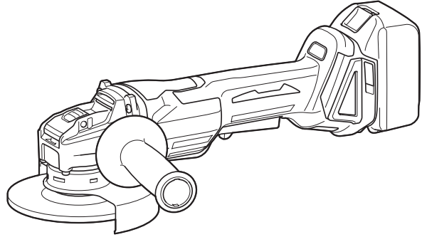
Makita DGA520 Cordless Angle Grinder Instruction Manual


| Model: | DGA520 |
| Wheel diameter | 125 mm (5″) |
| Max. wheel thickness | 6 mm |
| Rated speed (n) | 8,500 min-1 |
| Overall length | 376 mm |
| Rated voltage | D.C. 18 V |
| Net weight | 2.4 – 3.0 kg |
Due to our continuing program of research and development, the specifications herein are subject to change without notice.
- Specifications may differ from country to country.
- The weight may differ depending on the attachment(s), including the battery cartridge. The lightest and heaviest combinations, according to EPTA-Procedure 01/2014, are shown in the table.
Applicable battery cartridge and charger
| Battery cartridge | BL1815N / BL1820B / BL1830B / BL1840B / BL1850B / BL1860B |
| Charger | DC18RC / DC18RD / DC18RE / DC18SD / DC18SE / DC18SF / DC18SH |
Some of the battery cartridges and chargers listed above may not be available depending on your region of residence.
WARNING: Only use the battery cartridges and chargers listed above. Use of any other battery cartridges and chargers may cause injury and/or fire.
Recommended cord-connected power source
Portable power pack PDC01
- The cord-connected power source(s) listed above may not be available depending on your region of residence.
- Before using the cord-connected power source, read the instructions and cautionary markings on them.
Intended use
The tool is intended for trimming hedges.
Noise
The typical A-weighted noise level is determined according to EN62841-4-2:
Sound pressure level (LpA): 74 dB(A)
Uncertainty (K) : 3 dB(A)
The noise level under working may exceed 80 dB (A).
NOTE: The declared noise emission value(s) has been measured in accordance with a standard test method and may be used for comparing one tool with another.
NOTE: The declared noise emission value(s) may also be used in a preliminary assessment of exposure.
WARNING: Wear ear protection.
WARNING: The noise emission during actual use of the power tool can differ from the declared value(s) depending on the ways in which the tool is used especially what kind of workpiece is processed.
WARNING: Be sure to identify safety measures to protect the operator that are based on an estimation of exposure in the actual conditions of use (taking account of all parts of the operating cycle such as the times when the tool is switched off and when it is running idle in addition to the trigger time).
Vibration
Applicable standard: EN62841-4-2
The vibration total value (tri-axial vector sum) deter-mined according to EN60745-2-3:
- Work mode: surface grinding with normal side grip
- Vibration emission (ah, AG) : 5.5 m/s2 Uncertainty (K) : 1.5 m/s2
- Work mode: surface grinding with anti vibration side grip Vibration emission (ah, AG) : 7.0 m/s2
- Uncertainty (K) : 1.5 m/s2
NOTE: The declared vibration total value(s) has been measured in accordance with a standard test method and may be used for comparing one tool with another.
NOTE: The declared vibration total value(s) may also be used in a preliminary assessment of exposure.
WARNING: The vibration emission during actual use of the power tool can differ from the declared value(s) depending on the ways in which the tool is used especially what kind of workpiece is processed.
WARNING: Be sure to identify safety measures to protect the operator that are based on an estimation of exposure in the actual conditions of use (taking account of all parts of the operating cycle such as the times when the tool is switched off and when it is running idle in addition to the trigger time).
EC Declaration of Conformity
For European countries only
The EC declaration of conformity is included as Annex A to this instruction manual.
SAFETY WARNINGS
General power tool safety warnings
WARNING: Read all safety warnings, instructions, illustrations, and specifications provided with this power tool. Failure to follow all instructions listed below may result in electric shock, fire and/or serious injury.
Save all warnings and instructions for future reference.
The term “power tool” in the warnings refers to your mains-operated (corded) power tool or battery-operated (cordless) power tool.
Cordless Pole Hedge Trimmer Safety Warnings
- Keep all parts of the body away from the blade. Do not remove cut material or hold material to be cut when blades are moving. Blades continue to move after the switch is turned off. A moment of inattention while operating the hedge trimmer may result in serious personal injury.
- Carry the hedge trimmer by the handle with the blade stopped and take care not to operate any power switch. Proper carrying of the hedge trimmer will decrease the risk of inadvertent starting and resultant personal injury from the blades.
- When transporting or storing the hedge trimmer, always fit the blade cover. Proper handling of the hedge trimmer will decrease the risk of personal injury from the blades.
- When clearing jammed material or servicing the unit, make sure all power switches are off and the battery pack is removed or disconnected. Unexpected actuation of the hedge trimmer while clearing jammed material or servicing may result in serious personal injury.
- Hold the hedge trimmer by insulated gripping surfaces only, because the blade may contact hidden wiring. Blades contacting a “live” wire may make exposed metal parts of the hedge trimmer
“live” and could give the operator an electric shock. - Keep all power cords and cables away from the cutting area. Power cords or cables may be hidden in hedges or bushes and can be accidentally cut by the blade.
- Do not use the hedge trimmer in bad weather conditions, especially when there is a risk of lightning. This decreases the risk of being struck by lightning.
- To reduce the risk of electrocution, never use the pole hedge trimmer near any electrical power lines. Contact with or use near power lines may cause serious injury or electric shock resulting in death.
- Always use two hands when operating the pole hedge trimmer. Hold the pole hedge trimmer with both hands to avoid loss of control.
- Always use head protection when operating the pole hedge trimmer overhead. Falling debris can result in serious personal injury.
Additional Safety Instructions
Preparation
- Do not “jam“ the cut-off wheel or apply excessive pressure. Do not attempt to make an excessive depth of cut. Overstressing the wheel increases the loading and susceptibility to twisting or binding of the wheel in the cut and the possibil-ity of kickback or wheel breakage.
- Do not position your body in line with and behind the rotating wheel. When the wheel, at the point of operation, is moving away from your body, the possible kickback may propel the spin-ning wheel and the power tool directly at you.
- When the wheel is binding or when interrupting a cut for any reason, switch off the power tool and hold the power tool motionless until the wheel comes to a complete stop. Never attempt to remove the cut-off wheel from the cut while the wheel is in motion otherwise kickback may occur. Investigate and take corrective action to eliminate the cause of wheel binding.
- Do not restart the cutting operation in the workpiece. Let the wheel reach full speed and carefully re-enter the cut. The wheel may bind, walk up or kickback if the power tool is restarted in the workpiece.
- Support panels or any oversized workpiece to minimize the risk of wheel pinching and kick-back. Large workpieces tend to sag under their own weight. Supports must be placed under the workpiece near the line of cut and near the edge of the workpiece on both sides of the wheel.
6. Use extra caution when making a “pocket cut” into existing walls or other blind areas. The protruding wheel may cut gas or water pipes, elec-trical wiring or objects that can cause kickback.
Safety Warnings Specific for Wire Brushing Operations
- Be aware that wire bristles are thrown by the brush even during ordinary operation. Do not overstress the wires by applying excessive load to the brush. The wire bristles can easily penetrate light clothing and/or skin.
- If the use of a guard is recommended for wire brushing, do not allow any interference of the wire wheel or brush with the guard. Wire wheel or brush may expand in diameter due to work load and centrifugal forces.
Operation
- Always use two hands to operate the tool. Using one hand could cause loss of control and result in serious personal injury.
- While operating the tool, always ensure that the operating position is safe and secure. Overreaching with the tool, particularly from a ladder, is extremely dangerous. Do not work from anything wobbly or infirm.
- Do not simultaneously wear multiple belt harnesses and/or shoulder harnesses when operating the tool.
- During operation, keep bystanders or animals at least 15 m away from the tool. Stop the tool as soon as someone approaches.
- If the cutting tool strikes any object or the tool starts making unusual noise or vibration, switch off the tool and remove the battery cartridge immediately and allow the tool to stop. And then take the following steps:
- inspect for damage
- check for, and tighten any loose parts
- have any damaged parts replaced or repaired with genuine spare parts.
- Only use the tool for its intended purpose. Do not use the tool for any other purpose.
- Switch off the tool and remove the battery cartridge before:
- cleaning or when clearing a blockage,
- checking, carrying out maintenance, or working on the tool,
- adjusting the working position of the shear blades,
- leaving the tool unattended.
- Ensure that the tool is correctly located in a designated working position before starting the tool.
- Do not operate the tool with damaged or excessively worn shear blades.
- Always be aware of your surroundings and stay alert for possible hazards of which you may not be aware due to the noise of the tool.
- Be careful not to accidentally contact a metal fence or other hard objects during operation. The blade will break and may cause serious injury.
- Avoid unintentional starting. Do not carry the tool when the battery cartridge is installed and with a finger on the switch. Make sure that the switch is off when installing the battery cartridge.
- Do not grasp the exposed cutting blades or cutting edges when picking up or holding the tool.
- Do not force the tool. It will do the job better and with less likelihood of a risk of injury at the rate for which it was designed.
- Do not use the tool in the rain or in wet or very damp conditions. The electric motor is not waterproof.
- Hold the tool firmly when using the tool.
- Do not operate the tool at no-load unnecessarily.
- Before checking the shear blades, taking care of faults, or removing foreign objects caught in the shear blades, always switch off the tool and remove the battery cartridge.
- Never point the shear blades to yourself or others.
- If the blades stop moving due to the stuck of foreign objects between the blades during operation, switch off the tool and remove the battery cartridge, and then remove the foreign objects using tools such as pliers. Removing the foreign objects by hand may cause an injury for the reason that the blades may move in reaction to removing the foreign objects.
Electrical and battery safety
- Avoid dangerous environments. Don’t use the tool in damp or wet locations or expose it to rain. Water entering the tool will increase the risk of electric shock.
- Do not dispose of the battery(ies) in a fire. The cell may explode. Check with local codes for possible special disposal instructions.
- Do not open or mutilate the battery(ies). Released electrolyte is corrosive and may cause damage to the eyes or skin. It may be toxic if swallowed.
- Do not charge the battery in rain, or in wet locations.
- Do not charge the battery outdoors.
- Do not handle chargers, including charger plug, and charger terminals with wet hands.
Maintenance and storage
- When the tool is stopped for servicing, inspection or storage, switch off the tool and remove the battery cartridge, and make sure all moving parts have come to a stop. Allow the tool to cool before making any inspections, adjustment, etc.
- Always allow the tool to cool down before storing.
- When not in use, attach the blade cover to the tool and store the tool indoors in dry, and high locked-up place, out of reach of children.
- Maintain the tool with care. Keep the cutting edge sharp and clean for best performance and to reduce the risk of injury. Follow instructions for lubricating and changing accessories. Keep grips dry, clean, and free from oil and grease.
- Check damaged parts. Before further use of the tool, any part which is damaged should be carefully checked to determine that it will operate properly and perform its intended function. Check for alignment of moving parts, binding of moving parts, breakage of parts, mounting, and any other condition that may affect its operation. A guard or other part that is damaged should be properly repaired or replaced by your authorized service center.
- Use genuine spare parts only.
- When moving the tool to another location, including during work, always remove the battery cartridge and put the blade cover on the shear blades. Never carry or transport the tool with the blades running. Never grasp the blades with your hands.
- Clean the tool and especially the shear blades after use, and before putting the tool into storage for extended periods. Lightly oil the shear blades and put them on the blade cover.
- Do not dispose of the battery(ies) in a fire. The cell may explode. Check with local codes for possible special disposal instructions.
- Do not open or mutilate the battery(ies). Released electrolyte is corrosive and may cause damage to the eyes or skin. It may be toxic if swallowed.
- Do not charge the battery in rain, or in wet locations.
SAVE THESE INSTRUCTIONS.
WARNING: DO NOT let comfort or familiarity with product (gained from repeated use) replace strict adherence to safety rules for the subject product. MISUSE or failure to follow the safety rules stated in this instruction manual may cause serious personal injury.
Important safety instructions for battery cartridge
- Before using battery cartridge, read all instructions and cautionary markings on (1) battery charger, (2) battery, and (3) product using the battery.
- Do not disassemble or tamper with the battery cartridge. It may result in a fire, excessive heat, or explosion.
- If operating time has become excessively shorter, stop operating immediately. It may result in a risk of overheating, possible burns and even an explosion.
- If electrolyte gets into your eyes, rinse them out with clear water and seek medical attention right away. It may result in loss of your eyesight.
- Do not short the battery cartridge:
- Do not touch the terminals with any conductive material.
- Avoid storing battery cartridges in a container with other metal objects such as nails, coins, etc.
- Do not expose the battery cartridge to water or rain. A battery short can cause a large current flow, overheating, possible burns and even a breakdown.
- Do not store and use the tool and battery car-tridge in locations where the temperature may reach or exceed 50 °C (122 °F).
- Do not incinerate the battery cartridge even if it is severely damaged or is completely worn out. The battery cartridge can explode in a fire.
- Do not nail, cut, crush, throw, drop the battery cartridge, or hit a hard object to the battery cartridge. Such conduct may result in a fire, excessive heat, or explosion.
- Do not use a damaged battery.
- The contained lithium-ion batteries are subject to the Dangerous Goods Legislation requirements.
For commercial transports e.g. by third parties or forwarding agents, special requirements on pack-aging and labeling must be observed.
For the preparation of the item being shipped, consulting an expert for hazardous material is required. Please also observe possibly more detailed national regulations.
Tape or mask off open contacts and pack up the battery in such a manner that it cannot move around in the packaging. - When disposing of the battery cartridge, remove it from the tool and dispose of it in a safe place. Follow your local regulations relating to the disposal of batteries.
- Use the batteries only with the products specified by Makita. Installing the batteries to non-compliant products may result in a fire, excessive heat, explosion, or leak of electrolyte.
- If the tool is not used for a long period of time, the battery must be removed from the tool.
- During and after use, the battery cartridge may take on heat which can cause burns or low-temperature burns. Pay attention to the handling of hot battery cartridges.
- Do not touch the terminal of the tool immediately after use as it may get hot enough to cause burns.
- Do not allow chips, dust, or soil to stuck into the terminals, holes, and grooves of the battery cartridge. It may result in poor performance or breakdown of the tool or battery cartridge.
- Unless the tool supports the use near high-voltage electrical power lines, do not use the battery cartridge near high-voltage electrical power lines. It may result in a malfunction or breakdown of the tool or battery cartridge.
- Keep the battery away from children.
SAVE THESE INSTRUCTIONS.
CAUTION: Only use genuine Makita batteries. Use of non-genuine Makita batteries, or batteries that have been altered, may result in the battery bursting causing fires, personal injury and damage. It will also void the Makita warranty for the Makita tool and charger.
Tips for maintaining maximum battery life
- Charge the battery cartridge before completely discharged. Always stop tool operation and charge the battery cartridge when you notice less tool power.
- Never recharge a fully charged battery cartridge. Overcharging shortens the battery service life.
- Charge the battery cartridge at room temperature at 10 °C – 40 °C (50 °F – 104 °F). Let a hot battery cartridge cool down before charging it.
- When not using the battery cartridge, remove it from the tool or the charger.
- Charge the battery cartridge if you do not use it for a long period (more than six months).
FUNCTIONAL DESCRIPTION
CAUTION: Always be sure that the tool is switched off and the battery cartridge is removed before adjusting or checking the function on the tool.
Installing or removing the battery cartridge
CAUTION: Always switch off the tool before installing or removing of the battery cartridge.
CAUTION: Hold the tool and the battery cartridge firmly when installing or removing the battery cartridge. Failure to hold the tool and the battery cartridge firmly may cause them to slip off your hands and result in damage to the tool and battery cartridge and a personal injury.
Fig.1: 1. Red indicator 2. Button 3. Battery cartridge
To install the battery cartridge, align the tongue on the battery cartridge with the groove in the housing and slip it into place. Insert it all the way until it locks in place with a little click. If you can see the red indicator as shown in the figure, it is not locked completely.
CAUTION: Always install the battery cartridge fully until the red indicator cannot be seen. If not, it may accidentally fall out of the tool, causing injury to you or someone around you.
CAUTION: Do not install the battery cartridge forcibly. If the cartridge does not slide in easily, it is not being inserted correctly.

Indicating the remaining battery capacity
Only for battery cartridges with the indicator
Fig.2: 1. Indicator lamps 2. Check button

Press the check button on the battery cartridge to indicate the remaining battery capacity. The indicator lamps light up for a few seconds.
NOTE: The first (far left) indicator lamp will blink when the battery protection system works.

Indicating the remaining battery capacity
When you turn the tool on, the battery indicator shows the remaining battery capacity.
Fig.3: 1. Battery indicator


Tool/battery protection system
The tool is equipped with a tool/battery protection system. This system automatically cuts off power to the motor to extend tool and battery life. The tool will automatically stop during operation if the tool or battery is placed under one of the following conditions:
Overload protection
When the tool or battery is operated in a manner that causes it to draw an abnormally high current, the tool automatically stops. In this situation, turn the tool off and stop the application that caused the tool to become overloaded. Then turn the tool on to restart.
Overheat protection
When the tool or battery is overheated, the tool stops automatically. In this case, let the tool and battery cool before turning the tool on again.
When the battery capacity is not enough, the tool stops automatically. In this case, remove the battery from the tool and charge the battery.


Switch action
WARNING: Before installing the battery cartridge into the tool, always check to see that the switch trigger actuates properly and returns to the “OFF” position when released.
WARNING: For your safety, this tool is equipped with the lock-off button which prevents the tool from unintended starting. Never use the tool if it starts when you pull the switch trigger without pressing the lock-off button. Ask your local Makita Service Center for repairs.
WARNING: Never disable the lock function or tape down the lock-off button.
NOTICE: Do not pull the switch trigger forcibly without pressing the lock-off button. The switch may break.
To prevent the switch trigger from being accidentally pulled, a lock-off button is provided.
To start the tool, press the lock-off button and pull the switch trigger. Release the switch trigger to stop. The lock-off button can be pressed from either the right or left side.
Fig.4: 1. Lock-off lever 2. Switch lever

Automatic speed change function
Fig.5: 1. Mode indicator


Accidental re-start preventive function
When installing the battery cartridge while pulling the switch lever, the tool does not start.
To start the tool, first, release the switch lever. Then pull the lock-off lever, and pull the switch lever.
Active Feedback sensing Technology
The tool electronically detects situations where the wheel or accessory may be at risk to be bound. In this situation, the tool is automatically shut off to prevent further rotation of the spindle (it does not prevent kickback).
To restart the tool, switch off the tool first, remove the cause of the sudden drop in the rotation speed, and then turn the tool on.
Soft start feature
The soft-start feature reduces starting the reaction.
Electric brake
The electric brake is activated after the tool is switched off. The brake does not work when the power supply is shut down, such as the battery is removed accidentally, with the switch still on.
ASSEMBLY
CAUTION: Always be sure that the tool is switched off and the battery cartridge is removed before adjusting or checking the function on the tool.
Installing side grip (handle)
CAUTION: Always be sure that the side grip is installed securely before operation.
Screw the side grip securely on the position of the tool as shown in the figure. Fig.6

Installing or removing wheel guard
WARNING: When using a depressed center wheel or wire wheel brush, the wheel guard must be fitted on the tool so that the closed side of the guard always points toward the operator.
WARNING: Make sure that the wheel guard is securely locked by the lock lever with one of the holes on the wheel guard.
WARNING: When using an abrasive cut-off/diamond wheel, be sure to use only the special wheel guard designed for use with cut-off wheels.
(In some European countries, when using a diamond wheel, the ordinary guard can be used. Follow the regulations in your country.)
For depressed center wheel, wire wheel brush / abrasive cut-off wheel, diamond wheel
- While pushing the lock lever, mount the wheel guard with the protrusions on the wheel guard aligned with the notches on the bearing box.
Fig.7: 1. Lock lever 2. Notch 3. Protrusion - While pushing the lock lever toward A, push in the wheel guard by holding down the portions B as shown in the figure.
Fig.8: 1. Wheel guard 2. Hole - While keeping the lock lever and wheel guard position as described in step 2, rotate the wheel guard toward C, and then, change the angle of the wheel guard according to the work.
Fig.9: 1. Wheel guard 2. Hole
To remove the wheel guard, follow the installation procedure in reverse.


When using a depressed center wheel
Optional accessory
WARNING: When using a depressed center wheel, the wheel guard must be fitted on the tool so that the closed side of the guard always points toward the operator.
Fig.10: 1. Depressed center wheel 2. Wheel guard

When using an abrasive cut-off/diamond wheel
Optional accessory
WARNING: When using an abrasive cut-off/diamond wheel, be sure to use only the special wheel guard designed for use with cut-off wheels.
(In some European countries, when using a diamond wheel, the ordinary guard can be used. Follow the regulations in your country.)
WARNING: NEVER use the cut-off wheel for side grinding.
► Fig.11:

- Abrasive cut-off wheel/diamond wheel
- Wheel guard for abrasive cut-off wheel/diamond wheel
When using a wire cup brush
Optional accessory
CAUTION: Do not use wire cup brush that is damaged, or which is out of balance. Use of dam-aged brush could increase potential for injury from contact with broken brush wires.
Fig.12: 1. Wire cup brush
Optional accessory

CAUTION: Do not use wire wheel brush that is damaged, or which is out of balance. Use of a damaged wire wheel brush could increase the potential for injury from contact with broken wires.
CAUTION: ALWAYS use guard with wire wheel brushes, assuring diameter of wheel fits inside the guard. The wheel can shatter during use and guard helps to reduce chances of personal injury.
Fig.13: 1. Wire wheel brush 2. Wheel guard

Installing or removing X-LOCK wheel
WARNING: Never actuate the release lever of the X-LOCK holder during operation. Make sure that the X-LOCK wheel has stopped completely when removing it. Otherwise, the X-LOCK wheel comes off from the tool and may cause serious injury.
CAUTION: Use only original X-LOCK wheels with the X-LOCK logo. This tool is dedicated to
X-LOCK.
The maximum clamping gauge of 1.6 mm can only be guaranteed with original X-LOCK wheels.
Use of any other wheels may lead to insecure clamp-ing, and cause the clamp tool to come loose.
CAUTION: Do not touch the X-LOCK wheel immediately after operation. It may be extremely hot and could burn your skin.
CAUTION: Make sure that the X-LOCK wheel and holder of the tool are not deformed and are free from dust or foreign matters.
CAUTION: Do not put your finger near the holder while installing or removing the X-LOCK wheel. It may pinch your finger.
CAUTION: Do not put your finger near the release lever while installing the X-LOCK wheel. It may pinch your finger.
NOTE: No additional parts such as inner flanges or lock nuts are required to install or remove the X-LOCK wheels.
- To install the X-LOCK wheel, make sure that both catches are in the unlocked position.
If not, push the release lever from A side to lift B side, then pull the release lever from B side as illustrated. The catches are set in the unlocked position.
Fig.14: 1. Catch 2. Release lever - Place a central position of the X-LOCK wheel on the holder.
Make sure the X-LOCK wheel is parallel to the flange surface and with the correct side facing up. - Push the X-LOCK wheel into the holder. The catches snap into the lock position with a click and fix the X-LOCK wheel.
Fig.15: 1. X-LOCK wheel 2. Holder 3. Flange surface 4. Catch - Make sure the X-LOCK wheel is fixed correctly. The surface of the X-LOCK wheel is no higher than the surface of the holder as shown in the figure.
If not, the holder must be cleaned or the X-LOCK wheel must not be used.
► Fig.16: 1. Surface of the holder 2. Surface of the
To remove the X-LOCK wheel, push the release lever from A side to lift B side, then pull the release lever from B side as illustrated.
The X-LOCK wheel is released and can be removed.
Fig.17: 1. Release lever


OPERATION
WARNING: It should never be necessary to force the tool. The weight of the tool applies adequate pressure. Forcing and excessive pressure could cause dangerous wheel breakage.
WARNING: ALWAYS replace wheel if tool is dropped while grinding.
WARNING: NEVER hit the workpiece with the wheel.
WARNING: Avoid bouncing and snagging the wheel, especially when working corners, sharp edges etc. This can cause loss of control and kickback.
WARNING: NEVER use tool with wood cutting blades and other saw blades. Such blades when used on a grinder frequently kick and cause loss of control leading to personal injury.
WARNING: Never actuate the release lever of the X-LOCK holder during operation. The X-LOCK wheel comes off from the tool and may cause serious injury.
WARNING: Make sure that the X-LOCK wheel is fixed firmly.
CAUTION: Never switch on the tool when it is in contact with the workpiece, it may cause an injury to the operator.
CAUTION: Always wear safety goggles or a face shield during operation.
CAUTION: After the operation, always switch off the tool and wait until the wheel has come to a complete stop before putting the tool down.
CAUTION: ALWAYS hold the tool firmly with one hand on housing and the other on the side grip (handle).
Grinding operation Grinding operation
Turn the tool on and then apply the wheel or disc to the workpiece.
In general, keep the edge of the wheel or disc at an angle of about 15° to the workpiece surface.
During the break-in period with a new wheel, do not work the grinder in forwarding direction or it may cut into the workpiece. Once the edge of the wheel has been rounded off by use, the wheel may be worked in both forward and backward direction.

Operation with abrasive cut-off/diamond wheel
WARNING: Do not “jam” the wheel or apply excessive pressure. Do not attempt to make an excessive depth of cut. Overstressing the wheel increases the loading and susceptibility to twisting or binding of the wheel in the cut and the possibility of kickback, wheel breakage and overheating of the motor may occur.
WARNING: Do not start the cutting operation in the workpiece. Let the wheel reach full speed and carefully enter into the cut moving the tool forward over the workpiece surface. The wheel may bind, walk up or kickback if the power tool is started in the workpiece.
WARNING: During cutting operations, never change the angle of the wheel. Placing side pres-sure on the cut-off wheel (as in grinding) will cause the wheel to crack and break, causing serious personal injury.
WARNING: A diamond wheel shall be oper-ated perpendicular to the material being cut.
Usage example: operation with abrasive cut-off wheel Fig.19


Operation with a wire cup brush
CAUTION: Check operation of brush by run-ning tool with no load, insuring that no one is in front of or in line with brush.
NOTICE: Avoid applying too much pressure which causes over bending of wires when using the wire cup brush. It may lead to premature breakage.
Usage example: operation with wire cup brush Fig.21
NOTICE: Avoid applying too much pressure which causes over bending of wires when using wire wheel brush. It may lead to premature breakage.
Usage example: operation with wire wheel brush Fig.22


MAINTENANCE
CAUTION: Always be sure that the tool is switched off and the battery cartridge is removed before attempting to perform inspection or maintenance.
NOTICE: Never use gasoline, benzine, thinner, alcohol or the like. Discoloration, deformation or cracks may result.
To maintain product SAFETY and RELIABILITY, repairs, any other maintenance or adjustment should be per-formed by Makita Authorized Service Centers, always using Makita replacement parts.
Air vent cleaning
The tool and its air vents have to be kept clean. Regularly clean the tool’s air vents or whenever the vents start to become obstructed.
Fig.23: 1. Exhaust vent 2. Inhalation vent
Fig.24: 1. Dust cover


OPTIONAL ACCESSORIES
CAUTION: These accessories or attachments are recommended for use with your Makita tool specified in this manual. The use of any other accessories or attachments might present a risk of injury to persons. Only use accessory or attachment for its stated purpose.
If you need any assistance for more details regarding these accessories, ask your local Makita Service Center.
Makita genuine battery and charger Fig.25

| 1 | Grip 36 |
| 2 | Wheel Guard (for grinding wheel) |
| 3 | Depressed center wheel |
| 4 | Wheel Guard (for cut-off wheel) *1 |
| 5 | Abrasive cut-off wheel / Diamond wheel |
| 6 | Wire wheel brush |
| 7 | Wire cup brush |
NOTE: *1 In some European countries, when using a diamond wheel, the ordinary guard can be used instead of the special guard covering the both side of the wheel. Follow the regulations in your country.
NOTE: Some items in the list may be included in the tool package as standard accessories. They may differ from country to country.