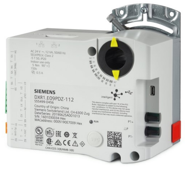
SIEMENS DXR1.E09PDZ Compact actuating room automation stations, BACnet/IP, AC 24 V User Manual


Desigo™ Room Automation
Compact actuating room automation stations, BACnet/IP,
AC 24 V (Actuating DXR)
DXR1.E09PDZ-112, DXR1.E09PLZ-112, DXR1.E09PDZ-113

Combination of room automation station and actuator for buildings with increasing demand on functionality and flexibility in Room Automation, VAV and FPB applications.
- Compact, configurable room automation station in combination with actuator for HVAC
- QMX1.M34H room unit and QMA1.N30H room sensor
- BACnet IP communications (BTL certified)
- 2-port Ethernet switch
- USB interface
- Operating voltage AC 24 V
- Built-in 5 or 10 Nm actuator
- Internal 0…500 Pa differential pressure sensor
- Plug-in terminal blocks
Features
Configurable
The DXR1.. automation stations provide the infrastructure for systems and application-specific functions which can be configured.
Compact series
The compact build allows direct mounting on the damper shaft. It is designed for VAV and FPB.
Plug-in terminal blocks
Plug-in terminal blocks for easy exchange of room automation stations.
Integrated actuator
The actuator gear base is integrated into the housing of the actuating XDR. It supports dampers with up to 5 or 10 Nm torque.
Use
Desigo Room Automation offers the highest level of flexibility for energy-optimized solutions while satisfying requirements for temperature control, ventilation and comfort using standard tools and established workflows.
Pre-installed application types
- Variable (VAV), Fan-Powered Box (FPB), and constant air volume flow
– With staged and modulating electric heating
– With modulating hot water / chilled water with a room or supply air temperature control
Application options
- Separate temperature and air volume flow setpoints for all 4 operating modes
- Separate minimum and maximum cooling and heating flow setpoints
- Single-stage, multi-stage or variable fan control (FPB/DXR1.E09PDZ-113)
- Chilled water and hot water valve
- Extract air volume flow control
Functions
The selected application and its parameters as well as input and output configuration determine the automation station’s functionality.
A detailed description of functionality is available in the ABT (Automation Building Tool) online help.
Communication
- 2-port Ethernet switch for cost-effective cabling via line topology.
Note: DXR1 supports cabling based on daisy chain topology. The max. the number is 20 devices and in the event of a failed automation station, all other stations are no longer reachable. DXR1 can be cabled as ring topology if higher reliability is required. This requires support for layer 2 switches RSTP (Rapid Spanning Tree Protocol) as well as SNMP monitoring and that any loss of the superposed system is reported. In the event of a fault, switching the communication paths can take between 10 and 30 seconds. DXR1 routes the RSTP protocol for the switches. It does not actually process the RSTP protocol. Further information can be found in the Application Guide for BACnet Networks in Building Automation (A6V11159798). - USB connection for service, commissioning, and firmware download.
LED indication
| LED | Color | Activity | Function |
| Run | Green | Steady ON | Device is ready for operation |
| Steady OFF | Device is not powered | ||
| Regular flashing | Start-up or the program is stopped | ||
| Red | Steady OFF | OK | |
| Steady ON | Program error Hardware fault | ||
| Rapid flashing | Wrong or corrupt software No application loaded | ||
| Blinking per wink command | Physical device identification | ||

Service button (SVC)
Physical identification on the network.
Technical / Mechanical design

| 1 | Service button (SVC) for sending device identification | 2 | 2 UIs (universal input), 1 AO (analog output) |
| 3 | Power supply | 4 | RJ45 interface for room unit |
| 5 | 4 DOs (digital Triac output) | 6 | Status information LED (bi-color) |
| 7 | 2-port Ethernet switch |
Housing
The housing consists essentially of flame retardant, non-brominated plastic.
Type summary
| Product No. | Stock No. | Inputs | Outputs | Description | Quantity |
| DXR1.E09PDZ-112 (5 Nm) | S55499-D456 | 2 universal inputs | 4 digital outputs, 1 analog output |
VAV application | Single package / multiple package (10) |
| DXR1.E09PLZ-112 (10 Nm) | S55499-D742 | 2 universal inputs | 4 digital outputs, 1 analog output |
VAV application | Single package / multiple package (10) |
| DXR1.E09PDZ-113 (5 Nm) | S55499-D457 | 2 universal inputs | 4 digital outputs, 1 analog output |
FPB application | Single package/multiple package (10) |
Ordering
When ordering, indicate product number, stock number and description.
Equipment combinations
| Product No. | Stock No. | Designation | Datasheet* |
| QMA1.N30H | S55499-D464 | Room temperature sensor for DXR1.. (without LCD) | A6V11393922 |
| QMX1.M34H | S55499-D465 | Room unit for DXR1.. (with LCD) | A6V11393927 |
* The documents can be downloaded from http://siemens.com/bt/download by specifying the
Datasheet number as shown in the above table.
Product documentation
| Topic | Title | Document ID: |
| Installation, cable length, topology | Desigo Room Automation installation guide | CM111043 |
| Engineering and commissioning | ABT online help | N/A |
| Installation instruction | Mounting instructions | A6V11393918 |
| Commissioning | Quick guide | A6V11526405 |
| Product environmental declaration | A6V11805930 | |
| EU declarations (CE) | A6V11791489 | |
Documents such as environmental declarations, CE declarations, etc., can be downloaded at the following Internet address: http://siemens.com/bt/download
Notes
Security
Failure to comply with national safety regulations may result in personal injury and property damage.


- Observe national provisions and comply with the appropriate safety regulations.
- Use only properly trained technicians for mounting, commissioning and servicing.
Engineering
Identification
Each device has a unique serial number to ensure efficient commissioning. It is provided on the adhesive barcode reader. The serial number can be read directly into the engineering tool using a barcode reader.
Wiring
Wiring must be sufficiently insulated to the available rated voltage. The sizing and fusing of the wiring depend on the connected load.
Mounting
The automation station is mounted directly on a damper shaft.

See the mounting instructions (document ID: A6V11393918) for detailed information.
Differential pressure sensor
- Avoid bends and pressure when attaching the tube.
- Connect the “+” connection on the side with the higher pressure and the “-” connection on the side with the lower pressure.
- Connection tubes (interior diameter) of 4 mm.
Air tube connection kit DXA.T50 for connection of tubes with 6.5 mm (interior diameter). - The maximum tube length is 2 m.
Installation
Applies to devices with supply output (AC 24 V or mains voltage) such as Triac output or output to supply a field device.
Risk of fire and injury due to short-circuits

- Adapt the line diameters as per local regulations to the rated value of the installed fuse.
Maintenance
The controller is maintenance-free.
Disposal

- Use only designated channels for disposing of the devices.
- Comply with all local and currently applicable laws and regulations.
Warranty
Technical data on specific applications are valid only together with Siemens products listed under “Equipment combinations”. Siemens rejects any and all warranties in the event that third-party products are used.
Technical data
Power data
| Power supply | |
| Operating voltage (SELV/PELV) | AC 24 V +/-20% |
| Frequency | 50 or 60 Hz |
| Power consumption | 7.5 VA max.: DXR1.E09PDZ-112, DXR1.E09PDZ-113 |
| 8 VA max.: DXR1.E09PLZ-112 | |
| Transformer requirements and recommended voltages | |
| Type | Class 2, AC 24 V, 50 / 60 Hz, SELV, PELV |
Functional data
| Functional data | |
| Nominal torque | 5 Nm / 10 Nm |
| Nominal rotary angle | 90 ° |
| Maximum rotary angle | 95 ° ± 2 ° |
| Runtime for 90 ° rotary angle | 150 s |
| Shaft size | 8…16 mm, round 8…10 mm, round (with centering insert) 6…12.8 mm square |
| Minimum shaft length | 20 mm |
Universal inputs
| Analog inputs: DC 0…10 V | |
| Operating range | 0…10 V |
| Resolution | 10 mV |
| Analog inputs: sensor | |||
| Type | Measuring range | Accuracy | Resolution |
| LG / DIN-Ni 1000 | 0…50 ℃ | +/- 0.5 K at 25 ℃ | 0.1 K at 25 ℃ |
| Pt1K, 375 / 385 | |||
| NTC10K / NTC100K | |||
| Digital inputs | |
| 0/1 digital signal (binary) | For potential free contacts |
| Sampling voltage/current | DC 15 V, 7 mA |
| Digital inputs | |
| Contact resistance | Max. 200 Ω (closed) Min. 50 kΩ (open) |
| Delay | 10 ms |
| Pulse frequency | Max. 20 Hz |
Outputs
| Analog output | |
| Control range | 0…10 V |
| Resolution | 50 mV |
| Output current | Max. 1 mA |
| Triac outputs | |
| Number of channels | 4 |
| Type | Requires AC 24 V source to allow switching: switching to phase (AC 24 V) or neutral (⏊) |
| Current rating | 0.5 A max. per channel |
| Voltage rating | AC 24 V +/-20 % |
| Max. load | 12 VA per channel |
Pressure sensor
| Pressure sensor | |
| Measurement range | 0…500 Pa |
| Sample rate | ≤ 500 ms |
| Overload range | 0…100 kPa |
| Measuring range accuracy Zero point accuracy Resolution | 3 %0.2 Pa 12 Bit |
Connections
| Interfaces | |
| Ethernet | Plugs: dual RJ45, 10M/100M fast Ethernet Interface type: IEEE 802.3 compliance Cable type: 100M STP CAT 5 |
| USB (2.0) | Type Micro B |
| Interface for room unit (QMA1.N30H and QMX1.M34H) | RJ45 (shield CAT 5-E) Max. wiring length: 30 m |
| Wiring connections | |
| Wiring lengths for signals | Signal lines: max. 80 m For analog inputs: max. 30 m |
Conformity
| Ambient conditions and protection classification | |
| Classification per IEC/EN 60730 Function of automatic control devices Pollution degree Overvoltage category |
Type 1 2 III |
| Design type | Device suited for use with equipment of safety classes I and II |
| Degree of protection of housing to IEC EN 60529 Room automation station | IP20 |
| Climatic ambient conditions Transport (packaged for transport) as per IEC EN 60721-3-2 Operation as per IEC/EN 60721-3-3 |
Class 2K3 Temperature -25…70 °C Air humidity 5…95 % (non-condensing) Class 3K5 Temperature -5…50 °C Air humidity 5…95 % (non-condensing) |
| Mechanical ambient conditions Transport as per IEC/EN 60721-3-2 Operation as per IEC/EN 60721-3-3 | Class 2M2 Class 3M2 |
| Standards, directives and approvals | |
| Product standard | IEC/EN 60730-1 Automatic electronic controls for household and similar use |
| EU conformity (CE) | A6V11791489 |
| RCM conformity | A6V11791498 |
| EAC conformity | Eurasian conformity |
| UL Approbation Federal Communications Commission |
UL as per UL916, http://ul.com/database cUL as per CSA – C22.2 No. 205 FCC CFR 47 Part 15 Class B |
| ICES003 | CAN ICES-3 (B)/NMB-3(B) |
| Environmental compatibility | The product environmental declaration (A6V11805930*) contains data on environmentally compatible product design and assessments (RoHS compliance, materials composition, packaging, environmental benefit, disposal). |
* The documents can be downloaded from http://siemens.com/bt/download.
FCC regulations
Modification of this device to receive cellular radiotelephone service signals is prohibited under FCC rules and federal law.
This equipment has been tested and found to comply with the limits for a Class B digital device, pursuant to part 15 of the FCC Rules. These limits are designed to provide reasonable protection against harmful interference in a residential installation. This equipment generates, uses, and can radiate radio frequency energy and, if not installed and used in accordance with the instructions, may cause harmful interference to radio communications. However, there is no guarantee that interference will not occur in a particular installation. If this equipment does cause harmful interference to radio or television reception, which can be determined by turning the equipment off and on, the user is encouraged to try to correct the interference by one or more of the following measures:
- Reorient or relocate the receiving antenna.
- Increase the separation between the equipment and receiver.
- Connect the equipment into an outlet on a circuit different from that to which the receiver is connected.
- Consult the dealer or an experienced radio/TV technician for help.
Changes or modifications not expressly approved by the party responsible for compliance could void the user’s authority to operate the equipment.
Statement
This device complies with part 15 of the FCC Rules. Operation is subject to the following two conditions: (1) This device may not cause harmful interference, and (2) this device must accept any interference received, including interference that may cause undesired operation.
General
| General information | |
| Color | Light gray |
| Dimensions | L × W × H = 137 × 143 × 82 mm |
| Weight | Net weight: 631.9 g Gross weight: 852.9 g |
Diagrams
Connection terminals
DXR1.E09PDZ-112, DXR1.E09PLZ-112 and DXR1.E09PDZ-113

| Pin | Description | Terminal |
| 1, 2 | IP connection | |
| USB | USB interface | |
| 81…82 power 24 V~ | Power supply AC 24 V | V~ |
| System neutral (must always be grounded at the transformer) | ⏊ | |
| 64…66 inputs | Universal inputs | X1, X2 |
| 62, 63 outputs | DC 0…10 V output | Y10 |
| 54…56 Triac outputs | Digital output, switching to phase (AC 24 V ) or neutral (⏊) | Y3, Y4 |
| 57…59 Triac outputs | Digital output, switching to phase (AC 24 V ) or neutral (⏊) | Y5, Y6 |
| Room unit connection | RJ45 interface | |
| ΔP differential pressure detector | Connected to the higher pressure | P1+ |
| Connected to the lower pressure | P1- | |
| Service | Service button | SVC |
| Display | Operation LED | RUN |


Dimensions
Dimensions in mm


Issued by
Siemens Switzerland Ltd
Smart Infrastructure
Global Headquarters
Theilerstrasse 1a
CH-6300 Zug
+41 58 724 2424
www.siemens.com/buildingtechnologies
© Siemens Switzerland Ltd, 2019
Technical specifications and availability subject to change without notice.
Document ID A6V11393931_en–_f
Edition
2021-11-01
