Huawei SUN2000-20KTL-M3 Three Phase Inverter User Guide

User Guide

Notice
- The information in this document is subject to change without notice. Every effort has been made in the preparation of this document to ensure the accuracy of the contents, but all statements, information, and recommendations in this document do not constitute a warranty of any kind, express or implied.
- Only qualified and trained electrical technicians are allowed to operate the device. Operation personnel should understand the composition and working principles of the grid-tied PV power system and local regulations.
- Before installing the device, read the user manual carefully to get familiar with product information and safety precautions. Huawei shall not be liable for any consequences caused by the violation of the storage, transportation, installation, and operation regulations specified in this document and the user manual.
- Use insulated tools when installing the device. For personal safety, wear proper personal protective equipment (PPE).
Overview
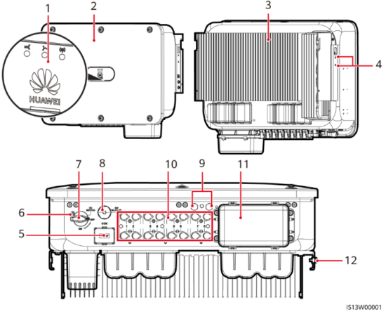

| (1) LED indicators (2) Host panel (3) Heat sink (4) Screws for fixing the awning (5) Communications port (COM) (6) Hole for the DC switch locking screw |
(7) DC switch (DC SWITCH) (8) Smart Dongle port (4G/WLAN-FE) (9) Ventilation valves (10) DC input terminals (PV1–PV8) (11) AC output port (12) Ground point |
Installation Requirements

Installing a Solar Inverter

- M12x40 bolt assemblies are supplied with the solar inverter. If the bolt length does not meet the installation requirements, prepare M12 bolt assemblies by yourself and use them together with the supplied M12 nuts.
- This quick guide describes how to install a solar inverter on support. For details about wall-mounted installation, see the user manual.
- For models used in Australia, install the DC switch locking screw according to local standards. The DC switch locking screw is delivered with the solar inverter to prevent the solar inverter from being started by mistake.
- Before installing the mounting bracket, remove the security Torx wrench and set it aside.

- Install the mounting bracket.
It is recommended that anti-rust measures be taken on the positions for drilling holes. - Install the solar inverter onto the mounting bracket.
- Tighten the security Torx screws on both sides.


Notice
Secure the screws on the sides before connecting cables.
Connecting Cables
Preparations
Notice
- Connect cables in accordance with local installation laws and regulations.
- The cable specifications must comply with local standards.
- Before connecting cables, ensure that the DC switch of the solar inverter and all the switches connected to it are set to OFF. Otherwise, the high voltage produced by the solar inverter may cause electric shocks.
| No. | Cable | Type | Specifications |
| 1 | PE cable | Single-core outdoor copper-core cable | Conductor cross-sectional area z 16 mm2 |
| 2 | AC output power cable | Outdoor copper- core/aluminum-core cable | • Conductor cross-sectional area: 16-50 mm2 outdoor copper-core cable or 3550 mm2 outdoor aluminum-core cable’ • Cable outer diameter: 16-38 mm |
| 3 | DC input power cable | Common outdoor PV cable in the industry (recommended model: PV1-F) | • Conductor cross-sectional area: 4-6 mm2 • Cable outer diameter: 5.5-9 mm |
| 4 | (Optional) RS485 communications cable | Two-core outdoor shielded twisted pair (recommended model: DJYP2VP2-2x2x0.75) | • Conductor cross-sectional area: 0.2-1 mm2 • Cable outer diameter: 4-11 mm |
| Note a: Five-core cables with a cross-sectional area of 5 x 35 mm2 or 5 x 50 mm2 are not supported. | |||
Connecting a PE Cable
Do not connect the neutral wire to the enclosure as a PE cable. Otherwise, electric shocks may occur.


- The PE point at the AC output port is used only as a PE equipotential point, not a substitute for the PE point on the enclosure.
- It is recommended that silica gel or paint be applied around the ground terminal after the PE cable is connected.
Installing the AC Output Power Cable
Notice
- Use a socket wrench and extension rod to connect the AC power cable. The extension rod must be longer than 100 mm.
- Sufficient slack should be provided in the PE cable to ensure that the last cable bearing the force is the PE cable when the AC output power cable bears pulling force due to force majeure.
- Do not install third-party devices in the AC connection box.
- You need to prepare M8 OT terminals by yourself.
- Remove the AC terminal box and install partition boards.
- Connect the AC output power cable (using a five-core cable as an example).


- To avoid damaging the rubber liner, do not route a cable with a crimped OT terminal directly through it.
- It is recommended that the length of the PE cable to be stripped be 15 mm longer than the length of other cables.
- The cable colors in the figures are for reference only. Select appropriate cables according to the local standards.
- A three-core AC output power cable can be connected similarly. The three-core cable (L1, L2, and L3) is not connected to the neutral wire or PE wire.
- A four-core or five-core AC output power cable can be connected similarly. The four-core cable (L1, L2, L3, and PE) is not connected to the N wire, and the four-core cable (L1, L2, L3, and N) is not connected to the PE wire.

Installing DC Input Power Cables
NOTICE
- Use the positive and negative Staubli MC4 metal terminals and DC connectors supplied with the solar inverter. Using incompatible positive and negative metal terminals and DC connectors may result in serious consequences. The caused device damage is not covered under any warranty.
- You are advised to use the PV-CZM-22100 (Staubli) crimping tool and not use it with the positioning block. Otherwise, the metal terminals may be damaged. The PV-MS (Staubli) or PV-MS-HZ (Staubli) open-end wrench is recommended.
- Ensure that the PV module output is well insulated to the ground.
- The DC input voltage of the SUN2000-29.9KTL/30KTL/36KTL/40KTL-M3 shall not exceed 1100 V DC under any circumstance.
- The DC input voltage of the SUN2000-20KTL-M3 shall not exceed 800 V DC under any circumstance.
- Before installing DC input power cables, label the cable polarities to ensure correct cable connections.
- If a DC input power cable is reversely connected and the DC switch is turned on, do not operate on the DC switch or the positive/negative connectors immediately. Otherwise, the device may be damaged. The caused device damage is not covered under any warranty. Wait until the night when solar irradiance declines and the PV string current drops to below 0.5 A. Then set the DC switch to the OFF position, remove the positive and negative connectors, and correct the polarity of the DC input power cable.
- If the SUN2000 is used with an optimizer, the number of optimizers for a single PV string cannot exceed 25.
- If the PV string is configured with an optimizer, check the cable polarity by referring to the smart PV optimizer quick guide.
1. Connect the DC power cables.

(Optional) Installing the Smart Dongle
NOTICE
- The Smart Dongle is not provided in standard configuration.
- For details about how to operate the WLAN-FE Smart Dongle SDongleA-05, see SDongleA-05 Quick Guide (WLAN-FE).
- For details about how to operate the 4G Smart Dongle SDongleA-03, see SDongleA-03 Quick Guide (4G).
- The quick guide is delivered with the Smart Dongle or can be obtained by scanning the QR codes.


NOTICE
Install the network cable before installing the Smart Dongle on the solar inverter.
4G Smart Dongle
NOTICE
- If your Smart Dongle is not equipped with a SIM card, prepare a standard SIM card (size: 25 mm, x 15 mm) with a capacity greater than or equal to 64 KB.
- When installing the SIM card, determine its installation direction based on the silkscreen and arrow on the card slot.
- Press the SIM card in place to lock it, indicating that the SIM card is correctly installed.
- When removing the SIM card, push it inwards to eject it.

Installing the Signal Cable
NOTICE
- When laying out the signal cable, separate it from the power cable and keep it away from strong interference sources to avoid strong communication interference.
- Ensure that the protective layer of the cable is inside the connector, that excess core wires are cut off from the protection layer, that the exposed core wire is totally inserted into the cable hole, and that the cable is connected securely.
COM Port Pin Definitions

| No. | Definition | Function | Description | No. | Definition | Function | Description |
| 1 | 485A1- 1 | RS485 differential signal + | Used to cascade inverters or connect to the SmartLogger. It can also connect to an EMI. | 2 | 485A1-2 | RS485 differential signal + | Used to cascade inverters or connect to the SmartLogger. It can also connect to an EMI. |
| 3 | 485B1-1 | RS485 differential signal – | 4 | 48581-2 | RS485 differential signal – | ||
| 5 | PE | The ground point on the shield layer | – | 6 | PE | Ground the point on the shield layer | – |
| 7 | 485A2 | RS485 differential signal + | Connects to the RS485 signal the port on the power grid scheduling power meter. |
8 | DIN1 | Dry contact for power grid scheduling | – |
| 9 | 48582 | RS485 differential signal – | 10 | DIN2 | |||
| 11 | – | – | – | 12 | DIN3 | ||
| 13 | GND | GND | – | 14 | DIN4 | ||
| 15 | DINS | Rapid shutdown | Supports AC NS protection shutdown, which can be used as a reserved port for rapid shutdown signals. | 16 | GND |
Scenarios Where No Signal Cable Is Connected
NOTICE
If no signal cable is required for the SUN2000, use waterproof plugs to block the wiring holes on the signal cable connector and connect the signal cable connector to the communications port on the SUN2000 to improve the waterproof performance of the SUN2000.

(Optional) Connecting the Signal Cable
- Connect the signal cable to the signal connector.
NOTICE
If two or more solar inverters are cascaded, install the RS485 communications cable. - Connect the signal cable connector to the communications port.


Verifying the Installation
| No. | Acceptance Criteria |
| 1 | The solar inverter is installed correctly and securely. |
| 2 | The cables are routed properly as required by the customer. |
| 3 | The communications expansion module is installed correctly and securely. |
| 4 | Cable ties are evenly distributed and no burr exists. |
| 5 | The PE cable is connected correctly and securely. |
| 6 | The DC switch and all the switches connected to the solar inverter are set to the OFF position. |
| 7 | The AC output power cable, DC input power cables, and signal cable are connected correctly and securely. |
| 8 | Unused terminals and ports are locked by watertight caps. |
| 9 | The installation space is proper, and the installation environment is clean and tidy. |
System Power-On
NOTICE
Before turning on the AC switch between the solar inverter and the power grid, check that the AC voltage is within the specified range using a multimeter set to the AC position.
- Turn on the AC switch between the solar inverter and the power grid.
- (Optional) Remove the locking screw beside the DC switch. Store the screws properly for future power-off maintenance.
- Turn on the DC switch at the bottom of the solar inverter.
- Observe the LED indicators to check the operating status of the solar inverter.

| Category | Status (Blinking Slowly: On for 1s and then Off for 1s; Blinking Fast: On for 0.2s and then Off for 0.2s) | Description | |
| Running indicator | |||
| Steady green | Steady green | The solar inverter is operating in grid-tied mode. | |
| Blinking green slowly | Off | The DC is on and the AC is off. | |
| Blinking green slowly | Blinking green slowly | Both the DC and AC are on, and the solar inverter is not supplying power to the power grid. | |
| Off | Blinking green slowly | The DC is off and the AC is on. | |
| Off | Off | Both the DC and AC are off. | |
| Blinking red fast | – | DC environment alarm | |
| – | Blinking red fast | AC environment alarm | |
| Steady red | Steady red | Fault | |
| Communications indicator | – | ||
| Blinking green fast | Communication is in progress. | ||
| Blinking green slowly | Mobile phone access | ||
| Off | No communication | ||
| Note: If LED1, LED2, and LED3 are steady red, the solar inverter is faulty and needs to be replaced. | |||


System Commissioning
- If the solar inverter is connected to the FusionSolar smart PV management system, the FusionSolar app is recommended. In areas (such as the UK) where the FusionSolar app is not available, or when a third-party management system is used, only the SUN2000 app can be used for commissioning.
- Access the Huawei app store (http://appstore.huawei.com), search for FusionSolar or SUN2000, and download the app installation package. You can also scan the QR codes below to download the apps.


NOTICE
- The screenshots are for reference only. The actual screens may vary.
- Obtain the initial password for connecting to the solar inverter WLAN from the label on the side of the solar inverter.
- Set the password at the first login. To ensure account security, change the password periodically and keep the new password in mind. Not changing the password may cause password disclosure. A password left unchanged for a long period of time may be stolen or cracked. If a password is lost, devices cannot be accessed. In these cases, the user is liable for any loss caused to the PV plant.
- Set the correct grid code based on the application area and scenario of the solar inverter.
The scenario in Which Solar Inverters Are Connected to the FusionSolar Smart PV Management System
- (Optional) Register an installer account.
If you already have an installer account, skip this step.
• Create the first installer account that will generate a domain named after the company. - Create a PV plant and a plant owner.


- In the quick settings for SUN2000(29.9KTL/36KTL/40KTL)M3, the grid code is N/A by default (automatic startup is not supported). Set the grid code based on the area where the PV plant is located.
- For details, see the FusionSolar App Quick Guide. You can scan the QR code to download the quick guide.

The scenario in Which Solar Inverters Are Connected to Other Management Systems
- Open the SUN2000 app, scan the QR code of the solar inverter or manually connect to the LLAN hotspot to access the device commissioning screen.
- Select installer and enter the login password.
- Tap Log in to access the quick settings screen or solar inverter home screen.

For details, see the FusionSolar App Quick Guide.

Inverter Connected to Optimizers
For details about how to add optimizers and the physical layout of optimizers, see SUN2000-450W-P Smart PV Optimizer Quick Guide and FusionSolar App Quick Guide. You can scan the QR codes to obtain the documents.


FAQ: How Do I Reset the Password?
- Check that the AC and DC power supplies to the solar inverter are connected simultaneously and that the
- Turn off the AC switch, set the DC switch at the bottom of the solar inverter to OFF, and wait until all indicators on the solar inverter panel turn off.
- Complete the following operations within 3 minutes:
a. Turn on the AC switch and wait until the
b. Turn off the AC switch and wait until all indicators on the solar inverter panel turn off.
c. Turn on the AC switch and wait until all LED indicators on the inverter panel blink and turn off after about 30s. - Wait until the three indicators on the inverter panel blink green quickly and then blink red quickly, indicating that the password has been restored.
- Reset the password within 10 minutes. (If no operation is performed within 10 minutes, all parameters of the solar inverter remain the same as those before the reset.)
a. Wait until the
b. Obtain the initial WLAN hotspot name (SSID) and initial password (PSW) from the label on the side of the solar inverter to connect to the app.
c. On the login page, set a new login password and log in to the app. - Set router and management system parameters to implement remote management.


NOTICE
You are advised to reset the password in the morning or at night when the solar irradiance is low.


Huawei Technologies Co., Ltd.
Huawei Industrial Base, Bantian, Longgang
Shenzhen 518129 People’s Republic of China
solar.huawei.com
Issue: 06
Part Number: 31500EAC
Date: 2022-01-04
HUAWEI TECHNOLOGIES CO., LTD.