Panasonic Micro Laser Distance Sensor Instruction Manual


Panasonic Micro Laser Distance Sensor

ME-HGC1000 No.0059-28V
Thank you very much for purchasing Panasonic products.
Please read this Instruction Manual carefully and thoroughly for the correct and optimum use of this product.
Kindly keep this manual in a convenient place for quick reference.
WARNING
- This product is for the sensing (determination and measurement) of objects. Do not use this product to secure safety, such as accident prevention which may affect human life and property.
- Do not stare directly into the laser beam, or through observation optical equipment, such as lenses or etc. as it is dangerous.
INTENDED PRODUCTS FOR CE MARKING
- This product complies with the following standards / regulations. <EU Directive>
EMC Directive
<Standards in US / Canada>
CAN/CSA-C22.2 NO. 60947-5-2-14
CONFIRMATION OF PACKED CONTENTS
- Sensor 1 pc.
- Laser warning label (JIS Standards, GB Standard) 1 set each
- FDA certification label 1 pc.
- Instruction Manual (Japanese, English, Korean) 1 pc. each language
- General Information for Safety, Compliance, and Instructions (23 languages) 1 pc.
SAFE USE OF LASER PRODUCT
For the purpose of preventing any injury which may occur to the user by the use of the laser product in advance, the following standards have been established by the IEC Standards, JIS Standards, GB Standards and FDA Standards.
IEC : IEC 60825-1-2014
JIS : JIS C 6802-2014
GB : GB 7247.1-2012
FDA : PART 1040.10
These standards classifies laser products according to the level of hazard and provide the safety measures for respective classes.
FDA Standards Outline
|
Requirements |
Class*1 | |||||
| I | IIa | II | IIIa | IIIb | IV | |
| Performance (all laser products) Protective housing [1040.10 (f) (1)] Safety interlocks [1040.10 (f) (2)] Location of controls [1040.10 (f) (7)] Viewing optics [1040.10 (f) (8)] Scanning safeguards [1040.10 (f) (9)] |
R*2 R*3,4 N/A R R |
R*2 R*3,4 R R R |
R*2 R*3,4 R R R |
R*2 R*3,4 R R R |
R*2 R*3,4 R R R |
R*2 R*3,4 R R R |
| Performance (laser system) Remote control connector [1040.10 (f) (3)] Key control [1040.10 (f) (4)] Emission indicator [1040.10 (f) (5)] Beam attenuator [1040.10 (f) (6)] Reset [1040.10 (f) (10)] |
N/A N/A N/A N/A N/A |
N/A N/A N/A N/A N/A |
N/A N/A R R N/A |
N/A N/A R R N/A |
R R R*10 R N/A |
R R R*10 R R*13 |
| Performance (specific-purpose products) Medical [1040.11 (a)] Measurement, leveling, alignment [1040.11 (b)] Demonstration [1040.11 (c)] |
S S S |
S S S |
S S S |
S*8 S S |
S*8 NP S*11 |
S*8 NP S*11 |
| Labeling (all laser products) Certification / identification [1010.2,3] Protective housing [1040.10 (g) (6), (7)] Aperture [1040.10 (g) (4)] Class warning [1040.10 (g) (1), (2), (3)] |
R D*5 N/A N/A |
R R*5 N/A R*6 |
R R*5 R R*7 |
R R*5 R R*9 |
R R*5 R R*12 |
R R*5 R R*12 |
| Information (all laser products) User information [1040.10 (h) (1)] Product literature [1040.10 (h) (2) (i)] Service information [1040.10 (h) (2) (ii)] |
R N/A R |
R R R |
R R R |
R R R |
R R R |
R R R |
- R : Required
- N/A : Not applicable
- S : Same as for other products of that Class. Also see footnotes.
- NP : Not permitted
- D : Depends on level of interior radiation.
- Class is based on the maximum level of laser exposure during operation.
- Required wherever and whenever human access to laser radiation above Class I limits is not needed for products to perform its functions.
- Required for protective housings opened during operation or maintenance, if human access
thus gained is not always necessary when housing is opened. - The requirements for interlock differ depending on the class of inner radiation.
- The contents of label differ depending on the level and wavelength of laser radiation inside the protective housing.
- Warning statement label.
- CAUTION logotype.
- The method to measure the level of laser radiation to human body is required.
- CAUTION if 2.5mWcm-2 or less, DANGER is greater than 2.5mWcm-2
- Delay required between indication and emission.
- Exception should be provided for demonstration of laser products or light shows using laser of Class IIIb or IV.
- DANGER logotype.
- Required after August 20, 1986.
WARNING label

- An English warning label is attached to this product. When this product is used in Japan or China, peel off the English warning label, and attach the Japanese or Chinese warning label.
- When exporting this product to the United State of America attach the FDA certification label to the cable close to the sensing device.
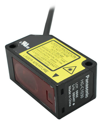
PART DESCRIPTION

MOUNTING

- When mounting this product, use M3 screws (prepare separately). Use a tightening torque of 0.5N・m for mounting.
- When mounting this product using the sensor mounting bracket (optional), also use a tightening torque of 0.5N・m.
Mounting Direction

- Direction to a movable body <When there are differences in material and color>
- When performing measurements of moving objects with excessively different materials and colors, mount the product per the
following directions to minimize measurement errors.
<Measurement of rotating objects> - When measuring rotating objects, mount the product as follows. Measurement can be performed with minimized effect on the object caused by up / down deflection, position deviation and etc. <When there is a step>
- When there is a step in the moving object, mount the product as follows. Measurement can be performed with minimized effect from the edges of the steps.
- Measuring of narrow locations and recesses
- When measuring in narrow locations or inside holes, mount the product so that optical path from the light emitting part to lightreceiving part is not interrupted.
- Mounting the sensor to a wall
- Mount the product as follows, so that the multiple light reflections on the wall do not emit to the lightreceiving part. When the reflection factor on a wall is high, it is effective to use a dull black color.
I/O CIRCUIT DIAGRAMS
- NPN Output Type
- PNP Output Type


TEACHING
This is the basic teaching method.

- Press the TEACH key in the background present condition.
- Press the TEACH key in the sensing object present condition.
- Stable sensing is possible
- Stable sensing is not possible
Limit-teaching
This is teaching method in case small object or object in background are existing.
<When an object in background is used as reference>
<When a sensing object is used as reference>


- Press the TEACH key in the background present condition or the sensing object present condition.
- When an object in the background is used as a reference, press the UP key to set the threshold on the sensor side. When a sensing object is used as a reference, press the DOWN key to set the threshold on the sensing object side.

1-point teaching (Window comparator mode)
- This is mode is used for setting the threshold range for the distance from the reference value of the sensing object, by performing 1-point teaching. This mode is used for sensing within the threshold range.
- When performing 1-point teaching (window comparator mode), preset “Window comparator mode 1” in the sensing output setting of the PRO mode. For the setting method, refer to “ 12 PRO MODE SETTING.”

- Press the TEACH key twice in the sensing object present condition. (1st time: TEACH mode, 2nd time: Teaching)
- Teaching is completed.
2-point teaching (Window comparator mode)
- This is method to set the threshold range by conducting the 2-point teaching.
- When performing 2-point teaching (window comparator mode), preset “Window comparator mode 2” in the sensing output setting of the PRO mode. For the setting, refer to “ 12 PRO MODE SETTING.”
- When conducting teaching, use sensing objects (P-1 and P-2) whose distance are different from each other.
- Press the TEACH key in the sensing object P-1 present condition. (1st time)
- Press the TEACH key in the sensing object P-2 present condition. (2nd time)
- Stable sensing is possible
- Stable sensing is not possible
3-point teaching (Window comparator mode)
- This is the method to perform 3-point teaching (P-1, P-2, P-3) and to set the threshold range by setting threshold 1_SL in the mid-point between the 1st time and 2nd time, and threshold 2_SL in the mid-point between the 2nd time and 3rd time as shown in the following figure.
- When performing 3-point teaching (window comparator mode), preset “Window comparator mode 3” in the sensing output setting of the PRO mode. For the setting, refer to “ 12 PRO MODE SETTING.”
- When performing teaching, use sensing objects (P-1, P-2, P-3) with different distance.
- After teaching, P-1, P-2 and P-3 will be automatically rearranged from the smaller value.
- Press the TEACH key in the sensing object P-1 present condition. (1st time)
- Press the TEACH key in the sensing object P-3 present condition. (3rd time)
- Press the TEACH key in the sensing object P-2 present condition. (2nd time)
Stable sensing is possible
Stable sensing is not possible

Span adjustment in rising differential mode or trailing differential mode
- This mode is used to cancel the gradual changes in the measured value, and to only detect sudden changes.
- When performing rising differential mode or trailing differential mode, preset “Rising differential mode” or “Trailing differential mode” in the sensing output setting of the PRO mode. For the setting method, refer to “ 12 PRO MODE SETTING.”
- The threshold can be set by using the threshold value fine adjustment function. For the threshold value fine adjustment function, refer to “ 8 THRESHOLD VALUE FINE ADJUSTMENT FUNCTION.”
- Press the TEACH key.
- Press the TEACH key to set.

THRESHOLD VALUE FINE ADJUSTMENT FUNCTION
- Fine adjustment of the threshold can be performed in the measurement display.
- Fine adjustment of the threshold can be performed even after teaching.
<Normal sensing mode, rising differential mode or trailing differential mode>

<Window comparator mode>
- When the sensing output is set to window comparator mode, the display of “ ” and “ ” can be changed by pressing the TEACH key for 1 second.


PEAK / BOTTOM HOLD FUNCTION
- The peak / bottom hold function, is for displaying the peak value and bottom value.
- When the zero set function is executed while the peak / bottom hold function is set to “Peak hold” or “Bottom hold”, the held measured value will be reset.
ZERO SET FUNCTION
- The zero set function is the function to compulsorily set the measured value to “zero”.
- T he zero set indicator (yellow) will turn ON when the zero set is valid.
- When the zero set function is executed while the peak / bottom hold function is valid, the held measured value will be reset.
- W hen the display setting is set to Offset, the zero set function cannot be set. <Zero set setting>
Even when the zero set is set in the sensor, the zero set can be set or released from an external input. However, when the power is turned ON again, the zero set set in the sensor will be displayed.

KEY LOCK FUNCTION
- The key lock function is to prevent acceptance of key operations, so that the conditions set in each setting mode are not changed accidentally.
- When key operation is performed after the key lock is set, “ ” will be displayed on the digital display.

PRO MODE SETTING
- The PRO indicator (yellow) will turn ON when the PRO mode is set.
- When the DOWN key is pressed for 3 seconds or more in the middle of the PRO MODE setting, the display returns to the measurement display.


- Do not use this product during the transient state when the power supply is turned ON.
- The overall length of the cable can be extended to 10m maximum with a cable size of 0.3mm2 or more.
- Make sure that stress by forcible bend or pulling is not applied to the sensor cable joint.
- Although it depends on the type, light from rapid start type or high frequency lighting type fluorescent lights, sunlight and etc. may affect the sensing, therefore make sure to prevent direct incident light.
- This product is suitable for indoor use only.
- Keep water, oil, fingerprints and etc. which reflect light, or dust, particles or etc. which interrupts the light, away from the emitting / receiving surfaces of this product. If contaminants adhere to the surface, wipe off with a dust-free soft cloth, or lens cleaning paper.
- Do not use the sensor in locations where there is excessive vapor, dust or etc. or in an atmosphere where corrosive gases, etc. is generated.
- Take care that the product does not come in contact with oil, grease, organic solvents such as thinner, etc., strong acid or alkaline.
- Make sure to turn OFF the power supply, before cleaning the light emitting / receiving windows of the sensor head.
- There is a certain deviation in the directionality of this product. Install the product using a mounting bracket or similar fitting to allow the adjustment of optical axis.
- The internal memory (nonvolatile) of this product has a service life. Settings cannot be configured more than 100,000 times.
ERROR INDICATION
| Error indication | Description | Remedy |
| <Hold OFF><Hold ON> Measured value blinks | Insufficient amount of reflected light. The sensing object is out of the sensing range. | Confirm that the sensing distance is within the specification range. Adjust the installation angle of the sensor. |
| Flash memory is damaged or passed its life expectancy. | Please contact our office. | |
| Load of the sensing output is short-circuited causing an over-current to flow. | Turn OFF the power and check the load. | |
| The semiconductor laser is damaged or passed its life expectancy. | Please contact our office. | |
| • When zero set is set, the measurement is not performed normally. • Since the display setting is set to “Offset”, the zero set function can not be used. |
• Confirm that the sensing distance is within the specification range. • Set the display to any setting except “Offset.” | |
| During teaching, the measurement is not per- formed normally. | Confirm that the sensing distance is within the specification range. | |
| System error | Please contact our office. |
SPECIFICATIONS
| Type | Measurement center 30mm type | Measurement center 50mm type | Measurement cen- ter 100mm type | Measurement cen- ter 200mm type | Measurement cen- ter 400mm type | ||
| Model No. | NPN output | HG-C1030 | HG-C1050 | HG-C1100 | HG-C1200 | HG-C1400 | |
| PNP output | HG-C1030- P | HG-C1050- P | HG-C1100- P | HG-C1200- P | HG-C1400- P | ||
| Measurement center distance | 30mm | 50mm | 100mm | 200mm | 400mm | ||
| Measurement range | ±5mm | ±15mm | ±35mm | ±80mm | ±200mm | ||
| Repeatability |
10μm |
30μm |
70μm |
200μm |
300μm (measurement distance 200 to 400mm) 800μm (measurement distance 400 to 600mm) | ||
| Linearity |
±0.1%F.S. |
±0.2%F.S. |
±0.2%F.S. (measurement distance 200 to 400mm) ±0.3%F.S. (measurement distance 400 to 600mm) | ||||
| Temperature characteristic | 0.03%F.S./°C | ||||||
| Light source | Red semiconductor laser Class 2 [JIS / IEC / GB / FDA (Note 2)] Max. output: 1mW, Emission peak wavelength: 655nm | ||||||
| Beam diameter (Note 3) | Approx. ø50μm | Approx. ø70μm | Approx. ø120μm | Approx. ø300μm | Approx. ø500μm | ||
| Supply voltage | 12 to 24V DC ±10%, Ripple P-P 10% or less | ||||||
| Power consumption | 40mA or less (at 24V DC supply voltage), 65mA or less (at 12V DC supply voltage) | ||||||
|
Control output |
<NPN output type> <PNP output type> NPN open-collector transistor PNP open-collector transistor • Maximum sink current: 50mA • Maximum source current: 50mA • Applied voltage: 30V DC or less • Applied voltage: 30V DC or less (Between control output to 0V) (Between control output to +V) • Residual voltage: 1.5V or less • Residual voltage: 1.5V or less (At 50mA sink current) (At 50mA source current) • Leakage current: 0.1 mA or less • Leakage current: 0.1 mA or less | ||||||
| Output operation | Switchable either Light-ON or Dark-ON | ||||||
| Short-circuit protection | Incorporated (Auto reset type) | ||||||
| Analog output |
Analog voltage output | • Output range: 0 to +5V (at alarm: +5.2V) • Output impedance: 100Ω | |||||
| Analog current output | • Output range: 4 to 20mA (at alarm: 0mA) • Load impedance: 300Ω or less | ||||||
| Response time | Switchable between 1.5ms / 5ms / 10ms | ||||||
|
External input |
<NPN output type> <PNP output type> NPN non-contact input PNP non-contact input • Input conditions • Input conditions Invalid: +8 to +V DC or Open Invalid: 0 to +0.6V DC or Open Valid: 0 to +1.2V DC Valid: +4 to +V DC • Input impedance: Approx. 10kΩ • Input impedance: Approx. 10kΩ | ||||||
| Protection | IP67 (IEC) | ||||||
| Degree of pollution | 2 | ||||||
| Ambient temperature | -10 to +45°C (No dew condensation or icing allowed), Storage: -20 to +60°C | ||||||
| Ambient humidity | 35 to 85% RH, Storage: 35 to 85% RH | ||||||
| Ambient illuminance | Incandescent lamp: Acceptance surface illuminance 3,000ℓx or less | ||||||
| Operating altitude | 2,000m or less | ||||||
| Cable | 0.2mm2 5-core composite cable, 2m long | ||||||
| Material | Enclosure: Aluminum die-cast, Front cover: Acrylic | ||||||
| Weight | Approx. 35g (without cable), approx. 85g (including cable) | ||||||
Notes:
- Supply voltage: 24V DC, ambient temperature: +20°C, response time: 10ms, and analog output value of measurement center distance are used for unspecified measurement conditions. The subject is white ceramics.
- This is based on the FDA Standard, according to Laser Notice No. 50 of the FDA Standard.
- This is the size in the measurement center distance. These values were defined by using 1/e2 (approx. 13.5%) of the center light intensity. Due to leak light outside the specified area, the reflectance around the detecting point may be higher than at the point and this may affect the measurement value.
CAUTIONS
- This product has been developed / produced for industrial use only.
- Make sure that the power supply is OFF before starting the wiring.
- If the wiring is performed incorrectly, it will cause a failure.
- Do not run the wires together with high-voltage lines or power lines, or put them in the same raceway. This can cause malfunction due to induction.
- Verify that the supply voltage variation is within the rating.
- If power is supplied from a commercial switching regulator, ensure that the frame ground (F.G.) terminal of the power supply is connected to an actual ground.
- If noise generating devices (switching regulators, inverter motors, etc.) are used around the sensor mounting area, make sure to connect the frame ground (FG) terminal of the device.