Yamaha DXS18 800W 18 inch Powered Subwoofer Owner’s Manual
YAMAHA DXS18 800W 18 inch Powered Subwoofer Owner’s Manual

Owner’s Manual
- The DXS18 is mainly used for the explanations in this manual.
- The illustrations as shown in this manual are for instructional purposes only.
- The company names and product names used in this manual are the trademarks or registered trademarks of their respective companies.
Introduction
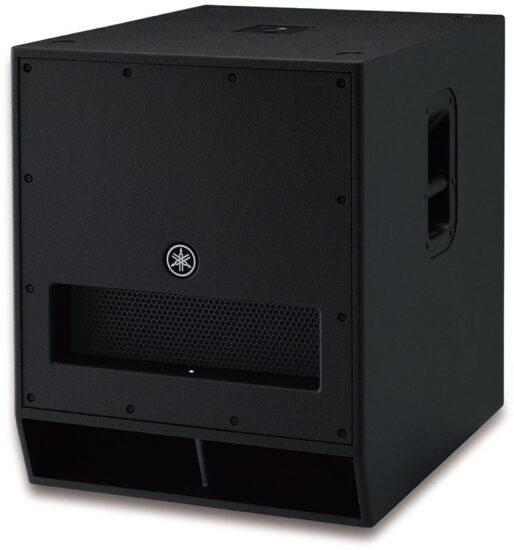
Thank you very much for purchasing the DXS Powered Subwoofer. The DXS is a powered subwoofer used for sound reinforcement and temporary installations. This owner’s manual explains how to set up and use the subwoofer in live venues and temporary PA installations to enhance low-end sound. Be sure to read this manual before using this subwoofer, in order to make sufficient use of the many functions that this product offers. Also, be sure to keep this manual after you are finished reading it.
Included accessories
- AC power cord
- Owner’s manual (this leaflet)
- Technical Specification
Optional accessories
- Speaker cover: SPCVR-18S01 (for DXS18), SPCVR-DXS152 (for DXS15mkII), SPCVR-DXS122 (for DXS12mkII)
- Wheels: SPW-1; 4 pieces
Features
- High power, high sound pressure, superior low-end playback capabilities
Adopting a bandpass type enclusure for high sound pressure. The DXS features a high-resistance input, low distortion woofer and a 1,020 W power amplifier to achieve superior low-end playback capability and high sound pressure. - Flexible features
- D-XSUB: D-XSUB is a DSP technology that gives users additional dynamic control of the frequency range to meet the demands of a variety of applications or musical styles.
- Selectable X-OVER (80/100/120 Hz): Selecting the cut-off frequency and LPF/HPF settings offers users more flexibility to adapt to various applications.
- Cardioid mode: The Cardioid mode setting adds additional control of low frequencies for sub-woofer arrays of two or more DXS speakers, effectively reducing the SPL of bass directed towards the stage while increasing the bass levels directed towards the audience.
- Reliability
A high-performance DSP control protects the speaker and amplifier. The DXS can be used worry-free, even under harsh operating conditions. - Durability
The DXS’s sturdy plywood cabinet is covered with an extremely durable polyurea finish that provides added protection from outside elements. - Fast and easy setup
M20 and Ø35 mm dual pole sockets allow for more flexible set up, while optional casters are also available for improved portability.
Controls and functions
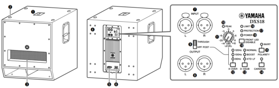

- Pole sockets
Adapts to commercially available speaker poles of 35 mm diameter and M20 screws. For details on installing speaker poles, refer to “Installing a Speaker Pole.” - Feet cups
When stacking multiple DXS units, align the rubber feet of the upper DXS unit to the feet cups of the lower.
Do not stack more than two DXS units. - Front LED
Turns on when the power is on. Lights more brightly when the output limiter is active. Using FRONT LED DISABLE switch (19) allows you to defeat the front LED altogether. - Wheel mounting holes
Optional SPW-1 wheels can be installed at these locations. For details on installing the wheels or special precautions you should take, please refer to the relevant manual for the wheels. - AC IN inlet (V-Lock)
Connect the AC power cord included with the unit. The AC power cord includes a locking mechanism with a latch. First connect the DXS to the AC power cord, and then connect the power cord to the AC outlet. When removing the cord, push the latch while pulling the cord out.
Turn off the power before you connect or disconnect the power cord. - Power switch
Turns the power to the unit on ( I ) or off ( O ).
If you are using multiple units, turn on the power to each unit one by one. If you turn on the power to multiple units simultaneously, a temporary drop in the power voltage may occur, possibly resulting in abnormal operation of the units.
Also, rapidly turning the unit on and off in succession can cause it to malfunction. After turning the unit off, wait for about 5 seconds before turning it on again.
A slight electrical current will flow even when the power switch is turned off. Make sure to unplug the power cord from the power outlet when not using the speaker for an extended period of time. - INPUT jacks
These are balanced input XLR jacks (line-level), and this device outputs the mixed signals of L and R. - OUTPUT jacks
These are balanced output XLR jacks for connecting full-range speakers or additional DXS units. The output signal can be switched via the THROUGH/HPF POST switch (9).
L/R output from the OUTPUT jacks correspond to L/R input to the INPUT jacks. The mixed signal of L/R is not output. - THROUGH/HPF POST switch
Switches the signals output from the OUTPUT jacks (8).
Make sure to lower the input level when switching.- THROUGH: Outputs unaffected signals from INPUT jacks (7). Select when using HPF of the connected speaker or connecting additional DXS units.
- HPF POST: Outputs signal input from INPUT jacks (7) after passing through a HPF. The cutoff frequency of the high pass filter is the frequency specified with the X-OVER switch (12). Because the output level from the OUTPUT jacks is linked to the LEVEL control (11), the levels of this unit and the full-range speaker change simultaneously.
- PEAK indicator
Lights red when the input level reaches 3 dB below clipping. If the indicator lights frequently, adjust the volume of the input source or lower the LEVEL control (11) so that the indicator flashes only briefly at the highest input levels. - LEVEL control
Adjusts the output level. - X-OVER switch
Specifies the crossover frequency at 120 Hz, 100 Hz, or 80 Hz. The output from the unit is processed through a low pass filter to cut the range of the selected frequency or higher. When setting THROUGH/HPF POST switch (9) to [HPF POST], the output signals from the OUTPUT jacks are processed through a high pass filter to cut the range of the selected frequency or lower, and the crossover frequency is linked to that of the connected speaker. - D-XSUB switch
Switches the low-range frequency response characteristics.- NORMAL: A generic setting corresponding to various applications.
- BOOST: Boosts the frequency range enhancing and providing punch to the sound.
- XTD LF (eXTenDed LF): Extends the bottom of the low frequency range.
- CARDIOID switch
Connection of multiple DXS units enables the use of Cardioid mode.
For details on Cardioid mode and using the switch, refer to “Setup of Cardioid Mode” on the opposite page. - POLARITY switch
Switches the polarity of the unit, normal or inverted. When the polarity is inverted, the INVRT indicator lights.
In most cases, this should be set to normal; however, the inverted setting may improve low-range response, depending on the type and location of the speaker system. Select a setting that produces the best low-end sound. - LIMIT indicator
Lights when the output limiter is active. The output limiter operates in order to protect the speaker and amplifier, attenuating the output signal to the amplifier. If the indicator lights frequently, adjust the volume of the input source or lower the LEVEL control (!1) so that the indicator only occasionally lights at the highest input levels. - PROTECTION indicator
Lights when the protection system is active. The protection system operates and the speaker output is muted in the following situations.- If amplifier overheating is detected.
- If overcurrent is detected.
- Immediately after turning the power on. (The protection system is activated to prevent noise and the indicator lights for about two seconds. The indicator turns off when the power supply has started normally.)
- POWER indicator
Lights when the power is on. - FRONT LED DISABLE switch
Turns the FRONT LED at the front of the unit on or off. The LED lights when this switch is set to off. Turn this switch on to disable the LED.

Basic Setup
- Input the output signal from a source, such as a mixer, to the INPUT jack of the DXS, and input the output signal from the OUTPUT jack of the DXS to the input jack of a full-range speaker.
- X-OVER switch (12)
It is recommended that you match the crossover frequency (the cutoff frequency of the low pass filter) of the DXS and the cutoff frequency of the high pass filter of the full-range speaker. The same frequency range output from the DXS and the full-range speaker may cause interference with each other and degrade the frequency characteristics. - THROUGH/HPF POST switch (9)
If the full-range speaker is properly equipped with a high pass filter, you should set this to [THROUGH]. The [THROUGH] setting enables you to control the level independently and minimize signal delay. If the full-range speaker is not equipped with a high pass filter or the high pass filter in the full-range speaker cannot be set to the same cutoff frequency as that of the low pass filter of the DXS, set this to [HPF POST] to use the high pass filter in the DXS.
Combination and setting examples

| Using the high pass filter in the connected full-range speaker | Using the high pass filter in the DXS | |
| Full-range speaker | ||
| DXS |


If multiple powered speakers are connected in daisy-chain fashion, turn each device on in sequence starting from the one nearest to the sound source, and turn them off starting from the one farthest from the sound source.
Combination of monaural DXS and stereo full-range speakers

Combination of stereo DXS and stereo full-range speakers
NOTE
The L and R jacks are interchangeable; there is no difference in behavior between them.

Installing a Speaker Pole
This is a pole socket used to mount a full-range speaker atop the DXS. The pole socket is compatible with 35 mm or M20 speaker poles, available commercially. When using the pole socket, be sure that the following conditions are met.

| Subwoofer | Top-mounted speaker | Pole length |
| DXS18 | Weight 28.0 kg or less, height 76 cm or less (DSR115) | 120 cm or less |
| DXS15mkII | Weight 19.3 kg or less, height 61 cm or less (DXR12) | 100 cm or less |
| DXS12mkII | Weight 14.6 kg or less, height 51 cm or less (DXR10) | 82 cm or less |
| Weight 13.5 kg or less, height 46 cm or less (DXR8) | 90 cm or less |
Installing Wheels
Installing optional wheels SPW-1 at the back of the DXS enables you to transport the unit easily. To install the wheels, use the screws already installed in the DXS unit. Please do not use the speaker once the screws are removed. This causes air leaks to occur in enclosure, resulting in undesirable performance.
- For details on installing the wheels or special precautions you should take, please refer to the relevant manual for the wheels.
- Do not install wheels other than the SPW-1.

Troubleshooting
Symptom |
Possible causes | Possible solution |
| Power does not turn on. | The power cord is not con- nected properly. | Connect the power cord properly. |
| Power suddenly turned off. | The protection system has been activated, shutting down the power supply. | Turn off the power, wait until the amplifier cools down, and then turn on again. |
| No sound. | The cable is not connected properly. | Connect the cable to the INPUT jack properly. |
| Sound is interrupted suddenly. | The protection circuit has been activated, muting the output. | Wait until the amplifier cools down. If the unit doesn’t automatically reset itself, turn off the power, and then on again. |
| Sound howls (feed- back). | A microphone is directed toward the speaker. | Keep the speaker away from the area where the microphone picks up the sound. |
| The sound from each speaker differs (if multiple speakers are used.) | The settings for each speaker differ. | Set each switch of each speaker to the same position. |
| Sound is distorted. | Input volume is excessive. | Lower the volume of the input device so that the PEAK indicator lights only occasionally. |
| Output volume is excessive. | Lower the output level with the LEVEL control so that the LIMIT indicator lights only occasionally. |
* If any specific problem should persist, please contact your Yamaha dealer.
General Specifications
| General Specifications | DXS18 | DXS15mkII | DXS12mkII | ||
| System Type | Powered subwoofer, band-pass type | ||||
| Frequency Range (-10 dB) | 32 Hz–120 Hz | 40 Hz–150 Hz | 42 Hz–150 Hz | ||
| Measured Maximum SPL (Peak) Pink Noise @1m | 136 dB SPL | 135 dB SPL | 134 dB SPL | ||
| Power Amplifier | Power Rating | Dynamic | 1,020 W | ||
| Continuous | 800 W | ||||
| Power Consumption (1/8 output power) | 100 W | ||||
| Components | LF | 18″ cone, 4″ voice coil | 15″ cone, 2.5″ voice coil | 12″ cone, 2.5″ voice coil | |
| Dimensions
(W × H × D; including rubber feet) |
563 × 683 × 721 mm | 480 × 611 × 614 mm | 400 × 567 × 570 mm | ||
| Weight | 49.7 kg | 36.0 kg | 30.0 kg | ||
| Handles | Steel, side × 2 | ||||
| Pole Sockets (top surface) | Ø35 mm (depth: 80 mm), M20 (threaded depth: 25 mm) | ||||
| Connectors | Input | XLR3-31 × 2 | |||
| Output | XLR3-32 × 2 (THROUGH or HPF POST) | ||||
| Power | IEC AC inlet × 1 (V-Lock) | ||||
| Input Sensitivity (LEVEL: center) | +10 dBu | ||||
| Maximum Input Level | +24 dBu | ||||
The contents of this manual apply to the latest specifications as of the publishing date.
To obtain the latest manual, access the Yamaha website then download the manual file.
Setup of Cardioid Mode
Because directivity in the low frequency range is weak, the output sound from the subwoofer diffracts not only toward the audience but also to the stage in almost the same sound pressure. By using the Cardioid mode, bass to the audience is summed up and bass to the stage is canceled. This suppresses the bass volume on the stage, providing a greater allowance before howling, and provides more powerful bass for the audience.
NOTE
- Use the same model and input signal for the DXS. You can also use the units connected in daisy chain fashion with setting the OUTPUT jack to [THROUGH].
- To obtain the optimum Cardioid characteristics, locate the cabinet away from walls by more than 1.2 m.
Two-unit, side-by-side placement
Place the two DXS units facing in opposite directions. Set the CARDIOID switch of the DXS facing the audience to off, and that of the DXS facing the stage to on. Make sure that the other settings (LEVEL, POLARITY, X-OVER) of the units are set the same.

Two-unit, vertically stacked placement
You can also construct a system for Cardioid mode by vertically stacking two units. Set the CARDIOID switch of the DXS facing to the stage side to on. Make sure that the other settings (LEVEL, POLARITY, XOVER) of the units are set the same.
- When vertically stacking DXS units, make sure they are stable and not in danger of falling over.
- Align the rubber feet of the upper DXS unit to the feet cups of the lower DXS.
- When using vertically stacked DXS units, do not place any objects (such as full-range speakers or another DXS) on top of them or insert speaker poles.

- When a full-range speaker is connected subsequently.
- When a full-range speaker is connected subsequently and the high pass filter in the full-range speaker is not used, set this to [HPF POST].
Three-unit, side-by-side placement
Set the CARDIOID switch of only the DXS unit facing the stage to on. Set the levels of the two DXS units facing the audience to the same. Set the level of the DXS unit facing to the stage approximately 6 dB greater than the DXS units facing the audience.

About Cardioid mode
The distance between a speaker (A) facing to the audience sound source speaker and another speaker (B) facing to the stage is defined as d. A delay is applied to the sound from speaker B, equivalent to distance d.

The sound of each speaker is cancelled on the stage side and summed together on the audience side. The directional characteristics of this combination are represented in the polar pattern illustration at right. Since the form resembles a heart shape, it is called Cardioid mode.
Directional characteristics
PRECAUTIONS

PLEASE READ CAREFULLY BEFORE PROCEEDING
Please keep this manual in a safe place for future reference.
Always follow the basic precautions listed below to avoid the possibility of serious injury or even death from electrical shock, short-circuiting, damages, fire or other hazards. These precautions include, but are not limited to, the following:
Power supply/power cord
- Do not place the power cord near heat sources such as heaters or radiators, and do not excessively bend or otherwise damage the cord, place heavy objects on it, or place it in a position where anyone could walk on, trip over, or roll anything over it.
- Only use the voltage specified as correct for the device. The required voltage is printed on the name plate of the device.
- Use only the supplied power cord/plug.
If you intend to use the device in an area other than in the one you purchased, the included power cord may not be compatible. Please check with your Yamaha dealer. - Check the electric plug periodically and remove any dirt or dust which may have accumulated on it.
- When setting up the device, make sure that the AC outlet you are using is easily accessible. If some trouble or malfunction occurs, immediately turn off the power switch and disconnect the plug from the outlet. Even when the power switch is turned off, as long as the power cord is not unplugged from the wall AC outlet, the device will not be disconnected from the power source.
- Remove the electric plug from the outlet when the device is not to be used for extended periods of time, or during electrical storms.
- Be sure to connect to an appropriate outlet with a protective grounding connection. Improper grounding can result in electrical shock, fire, or damage.
Do not open
- This device contains no user-serviceable parts. Do not open the device or attempt to disassemble the internal parts or modify them in any way. If it should appear to be malfunctioning, discontinue use immediately and have it inspected by qualified Yamaha service personnel.
Water warning
- Do not expose the device to rain, use it near water or in damp or wet conditions, or place on it any containers (such as vases, bottles or glasses) containing liquids which might spill into any openings. If any liquid such as water seeps into the device, turn off the power immediately and unplug the power cord from the AC outlet. Then have the device inspected by qualified Yamaha service personnel.
- Never insert or remove an electric plug with wet hands.
Hearing loss
- Do not use the device for a long period of time at a high or uncomfortable volume level, since this can cause permanent hearing loss. If you experience any hearing loss or ringing in the ears, consult a physician.
- Before connecting the device to other devices, turn off the power for all devices. Also, before turning the power of all devices on or off, make sure that all volume levels are set to the minimum. Failing to do so may result in hearing loss, electric shock, or device damage.
- When turning on the AC power in your audio system, always turn on the device LAST, to avoid hearing loss and speaker damage. When turning the power off, the device should be turned off FIRST for the same reason.
Fire warning
- Do not place any burning items or open flames near the device, since they may cause a fire.
If you notice any abnormality
- If any of the following problems occur, immediately turn off the power switch and disconnect the electric plug from the outlet.
- The power cord or plug becomes frayed or damaged.
- Unusual smells or smoke are emitted.
- Some object has been dropped into the device.
- There is a sudden loss of sound during use of the device.
- Cracks or other visible damage appear on the device. Then have the device inspected or repaired by qualified Yamaha service personnel.
- If this device should be dropped or damaged, immediately turn off the power switch, disconnect the electric plug from the outlet, and have the device inspected by qualified Yamaha service personnel.
Always follow the basic precautions listed below to avoid the possibility of physical injury to you or others, or damage to the device or other property. These precautions include, but are not limited to, the following:
Power supply/power cord
- When removing the electric plug from the device or an outlet, always hold the plug itself and not the cord. Pulling by the cord can damage it.
Location
- Do not place the device in an unstable position where it might accidentally fall over and cause injuries.
- When installing the device:
- Make sure the top surface faces up; do not install on its sides or upside down.
- Do not use the device in a confined, poorly-ventilated location.
Inadequate ventilation can result in overheating, possibly causing damage to the device(s), or even fire. Make sure that there is adequate space around the device: at least 30 cm above, 30 cm at the sides and 30 cm behind.
- Do not use the speaker’s handles for suspended installation. Doing so can result in damage or injury.
- Do not hold the bottom of the device when transporting or moving it. In doing so, you may pinch your hands under the device, and result in injury.
- Do not press the rear panel of the device against the wall. Doing so may cause the plug to come in contact with the wall and detach from the power cord, resulting in short circuiting, malfunction, or even fire.
- Do not place the device in a location where it may come into contact with corrosive gases or salt air. Doing so may result in malfunction.
- Avoid being near the device during a disaster, such as an earthquake. Since the device may turn over or fall and cause injury, stay away from the device quickly and move to a safe place.
- Before moving the device, remove all connected cables.
- When transporting or moving the device, always use three or more people. Attempting to pick this unit up with only one or two people may result in lower back injuries, or the equipment may be dropped and damaged, resulting in injury.
- Be sure to adhere to the conditions for “Installing a Speaker Pole” when mounting the speaker on top using the pole socket. Tipping this unit over may break the unit, cause damage to the internal parts or result in personal injury.
Maintenance
- Remove the power plug from the AC outlet when cleaning the device.
Handling caution
- Do not insert your fingers or hands in any gaps or openings on the device (ports).
- Avoid inserting or dropping foreign objects (paper, plastic, metal, etc.) into any gaps or openings on the device (ports). If this happens, immediately turn off the power unplug the power cord from the AC outlet, and have the device inspected by qualified Yamaha service personnel.
- Do not operate the device if the sound is distorting. Prolonged use in this condition could cause overheating and result in fire.
- Avoid pulling the connected cables to prevent injuries or damage to the device by causing it to fall.
Yamaha cannot be held responsible for damage caused by improper use or modifications to the device.
NOTICE
To avoid the possibility of malfunction/damage to the product, or damage to other property, follow the notices below.
- Handling and maintenance
- Do not use the device in the vicinity of a TV, radio, AV equipment, mobile phone, or other electric devices. Otherwise, the device, TV, or radio may generate noise.
- Do not expose the device to excessive dust or vibration, or extreme cold or heat (such as in direct sunlight, near a heater, or in a car during the day), in order to prevent the possibility of panel disfiguration, unstable operation, or damage to the internal components.
- Do not place vinyl, plastic or rubber objects on the device, since this might discolor the panel.
- When cleaning the device, use a dry and soft cloth. Do not use paint thinners, solvents, cleaning fluids, or chemicalimpregnated wiping cloths.
- Condensation can occur in the device due to rapid, drastic changes in ambient temperature—when the device is moved from one location to another, or air conditioning is turned on or off, for example. Using the device while condensation is present can cause damage. If there is reason to believe that condensation might have occurred, leave the device for several hours without turning on the power until the condensation has completely dried out.
- When placing the speaker face down, always place it on a flat surface.
- Do not touch the speaker driver unit.
- Air blowing out of the ports is normal.
- Always turn the power off when the device is not in use.
- Connectors
- XLR-type connectors are wired as follows (IEC60268 standard): pin 1: ground, pin 2: hot (+), and pin 3: cold (–).
Information
- About this manual
- The illustrations as shown in this manual are for instructional purposes only.
- The company names and product names in this manual are the trademarks or registered trademarks of their respective companies.
- About disposal
- This product contains recyclable components. When disposing of this product, please contact the appropriate local authorities.

CAUTION:
TO REDUCE THE RISK OF ELECTRIC SHOCK,
DO NOT REMOVE COVER (OR BACK).
NO USER-SERVICEABLE PARTS INSIDE.
REFER SERVICING TO QUALIFIED SERVICE PERSONNEL.
The above warning is located on the rear of the unit.
Explanation of Graphical Symbols
IMPORTANT SAFETY INSTRUCTIONS
- Read these instructions.
- Keep these instructions.
- Heed all warnings.
- Follow all instructions.
- Do not use this apparatus near water.
- Clean only with dry cloth.
- Do not block any ventilation openings. Install in accordance with the manufacturer’s instructions.
- Do not install near any heat sources such as radiators, heat registers, stoves, or other apparatus (including amplifiers) that produce heat.
- Do not defeat the safety purpose of the polarized or grounding-type plug. A polarized plug has two blades with one wider than the other. A grounding type plug has two blades and a third grounding prong. The wide blade or the third prong are provided for your safety. If the provided plug does not fit into your outlet, consult an electrician for replacement of the obsolete outlet.
- Protect the power cord from being walked on or pinched particularly at plugs, convenience receptacles, and the point where they exit from the apparatus.
- Only use attachments/accessories specified by the manufacturer.
- Use only with the cart, stand, tripod, bracket, or table specified by the manufacturer, or sold with the apparatus. When a cart is used, use caution when moving the cart/apparatus combination to avoid injury from tip-over.
- Unplug this apparatus during lightning storms or when unused for long periods of time.
- Refer all servicing to qualified service personnel. Servicing is required when the apparatus has been damaged in any way, such as power-supply cord or plug is damaged, liquid has been spilled or objects have fallen into the apparatus, the apparatus has been exposed to rain or moisture, does not operate normally, or has been dropped.

WARNING
TO REDUCE THE RISK OF FIRE OR ELECTRIC SHOCK, DO NOT EXPOSE THIS APPARATUS TO RAIN OR MOISTURE.
FCC INFORMATION (U.S.A.)
- IMPORTANT NOTICE: DO NOT MODIFY THIS UNIT! This product, when installed as indicated in the instructions contained in this manual, meets FCC requirements. Modifications not expressly approved by Yamaha may void your authority, granted by the FCC, to use the product.
- IMPORTANT: When connecting this product to accessories and/or another product use only high quality shielded cables. Cable/s supplied with this product MUST be used. Follow all
installation instructions. Failure to follow instructions could void your FCC authorization to use this product in the USA.
NOTE: This product has been tested and found to comply with the requirements listed in FCC Regulations, Part 15 for Class “B” digital devices. Compliance with these requirements provides a reasonable level of assurance that your use of this product in a residential environment will not result in harmful interference with other electronic devices. This equipment generates/uses radio frequencies and, if not installed and used according to the instructions found in the users manual, may cause interference harmful to the operation of other electronic devices. Compliance with FCC regulations does not guarantee that interference will not occur in all installations. If this product is found to be the source of interference, which can be determined by turning the unit “OFF” and “ON”, please try to eliminate the problem by using one of the following measures:
Relocate either this product or the device that is being affected by the interference. Utilize power outlets that are on different branch (circuit breaker or fuse) circuits or install AC line filter/s.
In the case of radio or TV interference, relocate/reorient the antenna. If the antenna lead-in is 300 ohm ribbon lead, change the lead-in to co-axial type cable.
If these corrective measures do not produce satisfactory results, please contact the local retailer authorized to distribute this type of product. If you can not locate the appropriate retailer, please contact Yamaha Corporation of America, Electronic Service Division, 6600 Orangethorpe Ave, Buena Park, CA90620 The above statements apply ONLY to those products distributed by Yamaha Corporation of America or its subsidiaries.
* This applies only to products distributed by YAMAHA CORPORATION OF AMERICA.
Information for users on collection and disposal of old equipment:

By disposing of these products correctly, you will help to save valuable resources and prevent any potential negative effects on human health and the environment which could otherwise arise from inappropriate waste handling.
For more information about collection and recycling of old products, please contact your local municipality, your waste disposal service or the point of sale where you purchased the items.
For business users in the European Union:
If you wish to discard electrical and electronic equipment, please contact your dealer or supplier for further information.
Information on Disposal in other Countries outside the European Union:
This symbol is only valid in the European Union. If you wish to discard these items, please contact your local authorities or dealer and ask for the correct method of disposal.
Yamaha Pro Audio global website:
https://www.yamaha.com/proaudio/
Yamaha Downloads:
https://download.yamaha.com/