Makita MLT100N Table Saw Instruction Manual


INSTRUCTION MANUAL
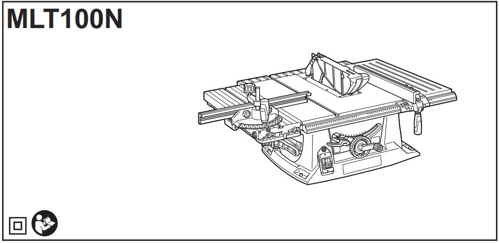


Original instructions
SPECIFICATIONS
| Model: | MLT1OON | |
| Arbor hole (Country specific) | 30 mm / 25.4 mm | |
| Blade diameter | 260 mm | |
| Max. cutting capacities | bevel 0° | 93 mm |
| bevel 45° | 64 mm | |
| No load speed | 4,300 min’ | |
| Table size (L x W) with sub tables (R) and (back) |
835 mm x 1,305 mm (tables extended) 685 mm x 955 mm (tables stored) | |
| Dimensions (L x W x H) with sub tables (R) and (back) |
726 mm x 984 mm x 473mm (tables stored) | |
| Net weight | 34.8 – 35.1 kg | |
| Safety class | ||

- Due to our continuing program of research and development, the specifications herein are subject to change without notice.
- Specifications may differ from country to country.
- The weight may differ depending on the attachment(s). The lightest and heaviest combination, according to EPTA-Procedure 01/2014, are shown in the table.
Symbols
The followings show the symbols used for the equipment.
Be sure that you understand their meaning before use.
| Read instruction manual. | |
| DOUBLE INSULATION | |
| Wear safety glasses. | |
| Do not place hand or fingers close to the blade. | |
| Make proper clearance between the saw blade and riving knife. | |
| Only for EU countries Do not dispose of electric equipment together with household waste material! In observance of the European Directive, on Waste Electric and Electronic Equipment and its implementation in accordance with national law, electric equipment that have reached the end of their life must be collected separately and returned to an environmentally compatible recycling facility. |


Intended use
The tool is intended for cutting in wood.
Straight cutting, bevel cutting, and miter cutting are available with this tool. This tool is not designed for nonthrough cutting.
Power supply
The tool should be connected only to a power supply of the same voltage as indicated on the nameplate, and can only be operated on single-phase AC supply. They are double-insulated and can, therefore, also be used from sockets without earth wire.
Noise
The typical A-weighted noise level determined according to EN62841-3-1:
Sound pressure level (LpA): 89 dB(A)
Sound power level (LWA) : 100 dB (A)
Uncertainty (K) : 3 dB(A)
NOTE: The declared noise emission value(s) has been measured in accordance with a standard test method and may be used for comparing one tool with another.
NOTE: The declared noise emission value(s) may also be used in a preliminary assessment of exposure.

EC Declaration of Conformity
For European countries only
The EC declaration of conformity is included as Annex A to this instruction manual.
SAFETY WARNINGS
General power tool safety warnings
WARNING: Read all safety warnings, instructions, illustrations and specifications provided with this power tool. Failure to follow all instructions listed below may result in electric shock, fire and/or serious injury.
Save all warnings and instructions for future reference.
The term “power tool” in the warnings refers to your mains-operated (corded) power tool or battery-operated (cordless) power tool.
Work area safety
- Keep work area clean and well lit. Cluttered or dark areas invite accidents.
- Do not operate power tools in explosive atmospheres, such as in the presence of flammable liquids, gases or dust. Power tools create sparks which may ignite the dust or fumes.
- Keep children and bystanders away while operating a power tool. Distractions can cause you to lose control.
Electrical Safety
- Power tool plugs must match the outlet. Never modify the plug in any way. Do not use any adapter plugs with earthed (grounded) power tools. Unmodified plugs and matching outlets will reduce risk of electric shock.
- Avoid body contact with earthed or grounded surfaces, such as pipes, radiators, ranges and refrigerators. There is an increased risk of electric shock if your body is earthed or grounded.
- Do not expose power tools to rain or wet conditions. Water entering a power tool will increase the risk of electric shock.
- Do not abuse the cord. Never use the cord for carrying, pulling or unplugging the power tool. Keep cord away from heat, oil, sharp edges or moving parts. Damaged or entangled cords increase the risk of electric shock.
- When operating a power tool outdoors, use an extension cord suitable for outdoor use. Use of a cord suitable for outdoor use reduces the risk of electric shock.
- If operating a power tool in a damp location is unavoidable, use a residual current device (RCD) protected supply. Use of an RCD reduces the risk of electric shock.
- Use of power supply via an RCD with a rated residual current of 30 mA or less is always recommended.
- Power tools can produce electromagnetic fields (EMF) that are not harmful to the user. However, users of pacemakers and other similar medical devices should contact the maker of their device and/ or doctor for advice before operating this power tool.
- Do not touch the power plug with wet hands.
- If the cord is damaged, have it replaced by the manufacturer or his agent in order to avoid a safety hazard.
Personal Safety
- Stay alert, watch what you are doing and use common sense when operating a power tool. Do not use a power tool while you are tired or under the influence of drugs, alcohol or medication. A moment of inattention while operating power tools may result in serious personal injury.
- Use personal protective equipment. Always wear eye protection. Protective equipment such as a dust mask, non-skid safety shoes, hard hat or hearing protection used for appropriate conditions will reduce personal injuries.
- Prevent unintentional starting. Ensure the switch is in the off-position before connecting to power source and/or battery pack, picking up or carrying the tool. Carrying power tools with your finger on the switch or energising power tools that have the switch on invites accidents.
- Remove any adjusting key or wrench before turning the power tool on. A wrench or a key left attached to a rotating part of the power tool may result in personal injury.
- Do not overreach. Keep proper footing and balance at all times. This enables better control of the power tool in unexpected situations.
- Dress properly. Do not wear loose clothing or jewellery. Keep your hair and clothing away from moving parts. Loose clothes, jewellery or long hair can be caught in moving parts.
- If devices are provided for the connection of dust extraction and collection facilities, ensure these are connected and properly used. Use of dust collection can reduce dust-related hazards.
- Do not let familiarity gained from frequent use of tools allow you to become complacent and ignore tool safety principles. A careless action can cause severe injury within a fraction of a second.
- Always wear protective goggles to protect your eyes from injury when using power tools. The goggles must comply with ANSI Z87.1 in the USA, EN 166 in Europe, or AS/NZS 1336 in Australia/New Zealand. In Australia/New Zealand, it is legally required to wear a face shield to protect your face, too.

Power tool use and care
- Do not force the power tool. Use the correct power tool for your application. The correct power tool will do the job better and safer at the rate for which it was designed.
- Do not use the power tool if the switch does not turn it on and off. Any power tool that cannot be controlled with the switch is dangerous and must be repaired.
- Disconnect the plug from the power source and/or remove the battery pack, if detachable, from the power tool before making any adjustments, changing accessories, or storing power tools. Such preventive safety measures reduce the risk of starting the power tool accidentally.
- Store idle power tools out of the reach of children and do not allow persons unfamiliar with the power tool or these instructions to operate the power tool. Power tools are dangerous in the hands of untrained users.
- Maintain power tools and accessories. Check for misalignment or binding of moving parts, breakage of parts and any other condition that may affect the power tool’s operation. If damaged, have the power tool repaired before use. Many accidents are caused by poorly maintained power tools.
- Keep cutting tools sharp and clean. Properly maintained cutting tools with sharp cutting edges are less likely to bind and are easier to control.
- Use the power tool, accessories and tool bits etc. in accordance with these instructions, taking into account the working conditions and the work to be performed. Use of the power tool for operations different from those intended could result in a hazardous situation.
- Keep handles and grasping surfaces dry, clean and free from oil and grease. Slippery handles and grasping surfaces do not allow for safe handling and control of the tool in unexpected situations.
- When using the tool, do not wear cloth work gloves which may be entangled. The entanglement of cloth work gloves in the moving parts may result in personal injury.
Service
- Have your power tool serviced by a qualified repair person using only identical replacement parts. This will ensure that the safety of the power tool is maintained.
- Follow instruction for lubricating and changing accessories.
Safety instructions for table saws
Guarding related warnings
- Keep guards in place. Guards must be in working order and be properly mounted. A guard that is loose, damaged, or is not functioning correctly must be repaired or replaced.
- Make sure the saw blade is not contacting the guard, riving knife or the workpiece before the switch is turned on. Inadvertent contact of these items with the saw blade could cause a hazardous condition.
- Adjust the riving knife as described in this instruction manual. Incorrect spacing, positioning and alignment can make the riving knife ineffective in reducing the likelihood of kickback.
- For the riving knife and anti-kickback pawls to work, they must be engaged in the workpiece. The riving knife and anti-kickback pawls are ineffective when cutting workpieces that are too short to be engaged with the riving knife and anti-kickback pawls. Under these conditions a kickback cannot be prevented by the riving knife and antikickback pawls.
- Use the appropriate saw blade for the riving knife. For the riving knife to function properly, the saw blade diameter must match the appropriate riving knife and the body of the saw blade must be thinner than the thickness of the riving knife and the cutting width of the saw blade must be wider than the thickness of the riving knife.
Cutting procedures warnings
- Feed the workpiece into the saw blade only against the direction of rotation. Feeding the workpiece in the same direction that the saw blade is rotating above the table may result in the workpiece, and your hand, being pulled into the saw blade.
- Never use the mitre gauge to feed the workpiece when ripping and do not use the rip fence as a length stop when cross cutting with the mitre gauge. Guiding the workpiece with the rip fence and the mitre gauge at the same time increases the likelihood of saw blade binding and kickback.
- When ripping, always apply the workpiece feeding force between the fence and the saw blade. Use a push stick when the distance between the fence and the saw blade is less than 150 mm, and use a push block when this distance is less than 50 mm. “Work helping” devices will keep your hand at a safe distance from the saw blade.
- Use only the push stick provided by the manufacturer or constructed in accordance with the instructions. This push stick provides sufficient distance of the hand from the saw blade.
- Never use a damaged or cut push stick. A damaged push stick may break causing your hand to slip into the saw blade.
- Do not perform any operation “freehand”. Always use either the rip fence or the mitre gauge to position and guide the workpiece. “Freehand” means using your hands to support or guide the workpiece, in lieu of a rip fence or mitre gauge. Freehand sawing leads to misalignment, binding and kickback.
- Never reach around or over a rotating saw blade. Reaching for a workpiece may lead to accidental contact with the moving saw blade.
- Provide auxiliary workpiece support to the rear and/or sides of the saw table for long and/or wide workpieces to keep them level. A long and/ or wide workpiece has a tendency to pivot on the table’s edge, causing loss of control, saw blade binding and kickback.
- Feed workpiece at an even pace. Do not bend or twist the workpiece. If jamming occurs, turn the tool off immediately, unplug the tool then clear the jam. Jamming the saw blade by the workpiece can cause kickback or stall the motor.
- Do not remove pieces of cut-off material while the saw is running. The material may become trapped between the fence or inside the saw blade guard and the saw blade pulling your fingers into the saw blade. Turn the saw off and wait until the saw blade stops before removing material.
- Use an auxiliary fence in contact with the table top when ripping workpieces less than 2 mm thick. A thin workpiece may wedge under the rip fence and create a kickback.

Kickback causes and related warnings
Kickback is a sudden reaction of the workpiece due to a pinched, jammed saw blade or misaligned line of cut in the workpiece with respect to the saw blade or when a part of the workpiece binds between the saw blade and the rip fence or other fixed object.
Most frequently during kickback, the workpiece is lifted from the table by the rear portion of the saw blade and is propelled towards the operator. Kickback is the result of saw misuse and/or incorrect operating procedures or conditions and can be avoided by taking proper precautions as given below.
- Never stand directly in line with the saw blade. Always position your body on the same side of the saw blade as the fence. Kickback may propel the workpiece at high velocity towards anyone standing in front and in line with the saw blade.
- Never reach over or in back of the saw blade to pull or to support the workpiece. Accidental contact with the saw blade may occur or kickback may drag your fingers into the saw blade.
- Never hold and press the workpiece that is being cut off against the rotating saw blade. Pressing the workpiece being cut off against the saw blade will create a binding condition and kickback.
- Align the fence to be parallel with the saw blade. A misaligned fence will pinch the workpiece against the saw blade and create kickback.
- Use extra caution when making a cut into blind areas of assembled workpieces. The protruding saw blade may cut objects that can cause kickback.
- Support large panels to minimise the risk of saw blade pinching and kickback. Large panels tend to sag under their own weight. Support(s) must be placed under all portions of the panel overhanging the table top.
- Use extra caution when cutting a workpiece that is twisted, knotted, warped or does not have a straight edge to guide it with a mitre gauge or along the fence. A warped, knotted, or twisted workpiece is unstable and causes misalignment of the kerf with the saw blade, binding and kickback.
- Never cut more than one workpiece, stacked vertically or horizontally. The saw blade could pick up one or more pieces and cause kickback.
- When restarting the saw with the saw blade in the workpiece, centre the saw blade in the kerf so that the saw teeth are not engaged in the material. If the saw blade binds, it may lift up the workpiece and cause kickback when the saw is restarted.
- Keep saw blades clean, sharp, and with sufficient set. Never use warped saw blades or saw blades with cracked or broken teeth. Sharp and properly set saw blades minimise binding, stalling and kickback.
Table saw operating procedure warnings
- Turn off the table saw and disconnect the power cord when removing the table insert, changing the saw blade or making adjustments to the riving knife, anti-kickback pawls or saw blade guard, and when the machine is left unattended. Precautionary measures will avoid accidents.
- Never leave the table saw running unattended. Turn it off and don’t leave the tool until it comes to a complete stop. An unattended running saw is an uncontrolled hazard.
- Locate the table saw in a well-lit and level area where you can maintain good footing and balance. It should be installed in an area that provides enough room to easily handle the size of your workpiece. Cramped, dark areas, and uneven slippery floors invite accidents.
- Frequently clean and remove sawdust from under the saw table and/or the dust collection device. Accumulated sawdust is combustible and may self-ignite.
- The table saw must be secured. A table saw that is not properly secured may move or tip over.
- Remove tools, wood scraps, etc. from the table before the table saw is turned on. Distraction or a potential jam can be dangerous.
- Always use saw blades with correct size and shape (diamond versus round) of arbour holes. Saw blades that do not match the mounting hardware of the saw will run off-centre, causing loss of control.
- Never use damaged or incorrect saw blade mounting means such as flanges, saw blade washers, bolts or nuts. These mounting means were pecially designed for your saw, for safe operation and optimum performance.
- Never stand on the table saw, do not use it as a stepping stool. Serious injury could occur if the tool is tipped or if the cutting tool is accidentally contacted.
- Make sure that the saw blade is installed to rotate in the proper direction. Do not use grinding wheels, wire brushes, or abrasive wheels on a table saw. Improper saw blade installation or use of accessories not recommended may cause serious injury.
Additional instructions
- Only use the saw blades that are marked with a speed equal or higher than the speed marked on the tool.
- Select the correct saw blade for the material to be cut.
- Wear gloves when handling saw blades.
- Clean the spindle, flanges (especially the installing surface) and hex nut before installing the blade. Poor installation may cause vibration/wobbling r slippage of the blade.
- Do not cut metal objects such as nails and screws. Inspect for and remove all nails, screws and other foreign material from the workpiece before operation.
- NEVER permit anyone else to stand in line with the path of the saw blade.
- Before using the tool on an actual workpiece, let it run for a while. Watch for vibration or wobbling that could indicate poor installation or a poorly balanced blade.
- The tool should not be used for slotting, rabbetting or grooving.
- Replace the table insert when worn.
- Always store the push-stick when it is not in use.
- Knock out any loose knots from workpiece BEFORE beginning to cut.
- Some dust created from operation contains chemicals known to cause cancer, birth defects or other reproductive harm Some examples of these chemicals are:
• lead from lead-based-painted material and,
• arsenic and chromium from chemically-treated lumber.
Your risk from these exposures varies, depending on how often you do this type of work. To reduce your exposure to these chemicals: work in a well ventilated area and work with approved safety equipment, such as those dust masks that are specially designed to filter out microscopic particles. - Always make sure that sub guard is down and flat against saw-table before plugging in the tool.
- Inspect extension cords periodically and replace if damaged.
- (For European countries only) Use only saw blades recommended by the manufacturer and which conform to EN847-1.
INSTALLATION
Positioning table saw
► Fig.1: 1. Hole diameter 8 mm
► Fig.2: 1. 6 mm Std. washer 2. No.10 wood screw 40 mm min. length
► Fig.3: 1. 6 mm Std. washer 2. 6 mm Mounting bolt & Nut tighten securely
Locate the table saw in a well lit and level area where you can maintain good footing and balance. It should be installed in an area that leaves enough room to easily handle the size of your workpieces. The table saw should be secured with four screws or bolts to the work bench or table saw stand using the holes provided in the bottom of the table saw. When securing the table saw on the work bench, make sure that there is an opening in the top of the work bench the same size as the opening in the bottom of the table saw so the sawdust can drop through. If during operation there is any tendency for the table saw to tip over, slide or move, the work bench or table saw stand should be secured to the floor.
Storing accessories
► Fig.4: 1. Triangular rule 2. Wrench 3. Push stick 4. Hex wrench 5. Saw blade 6. Lid
The push stick, triangular rule, saw blade and wrenches can be stored on the left side of the base. The saw blade can be stored inside the lid.
► Fig.5: 1. Anti-kickback pawls 2. Holder Place the anti-kickback pawls on the holder on the back of the base as illustrated. Turn the clamp to secure.
► Fig.6: 1. Rip fence (Guide rule) 2. Miter gauge The rip fence and miter gauge can be stored at the right side of the base.
FUNCTIONAL DESCRIPTION
Blade guard
► Fig.7: 1. Blade guard 2. Sub guard
When cutting, push the workpiece toward the blade with the lower edge of the sub guard contacting with the main table. As the workpiece is fed, the blade guard and the sub guard goes over the edge of the workpiece. In the interest of your personal safety, always maintain the blade guard and sub guard in good condition. Any irregular operation of the blade guard and sub guard should be corrected immediately. Check to assure that the blade guard and the sub guard are down and the lower edge of the sub guard contacts with the main table when the workpiece is not fed. If the see-through parts become dirty, or sawdust adheres to them in such a way that the blade and/or workpiece is no longer easily visible, unplug the tool and clean the see-through parts carefully with a damp cloth. Do not use solvents or any petroleum-based cleaners because this may cause damage to the parts. If see-through parts become discolored through age or UV light exposure, contact a Makita service center for a new parts. DO NOT DEFEAT OR REMOVE BLADE GUARD AND SUB GUARD.
Adjusting the depth of cut
► Fig.8: 1. Handle The depth of cut may be adjusted by turning the handle. Turn the handle clockwise to raise the saw blade or counterclockwise to lower it.
NOTE: Use a shallow depth setting when cutting thin materials in order to obtain a cleaner cut.
Adjusting the bevel angle
► Fig.9: 1. Lock lever 2. Arrow pointer 3. Handwheel
Loosen the lock lever counterclockwise and turn the handwheel until the desired angle (0° – 45°) is obtained. The bevel angle is indicated by the arrow pointer. After obtaining the desired angle, tighten the lock lever clockwise to secure the adjustment.
Adjusting positive stops
► Fig.10: 1. 90°Adjusting screw 2. 45°Adjusting screw
► Fig.11
The tool is equipped with positive stops at 90° and 45° to the table surface. To check and adjust the positive stops, proceed as follows:
Move the handwheel as far as possible by turning it. Place a triangular rule on the table and check to see if the saw blade is at 90° or 45° to the table surface. If the saw blade is at an angle shown in Fig. A, turn the adjusting screws clockwise; if it is at an angle shown in Fig. B, turn the adjusting screws counterclockwise to adjust the positive stops. After adjusting the positive stops, set the saw blade at 90° to the table surface. Then adjust the arrow pointer so that its right edge is aligned to the 0° graduation.
► Fig.12: 1. Arrow pointer
Switch action
► Fig.13: 1. ON ( I ) button 2. OFF ( O ) button 3. Restart button
To start the tool, press the ON ( I ) button.
To stop it, press the OFF ( O ) button.
Overload protection system
This tool is equipped with the overload prevention system. The tool stops and the restart button pops up when the tool is overloaded. In this case, perform the following procedures to restart the tool :
- Press the restart button.
- Press the ON ( I ) button.
Rip fence
► Fig.14: 1. Nut 2. Rip fence 3. Screw head
If the rip fence comes close to the saw blade, change the rip fence position. Loosen the nuts and slide the rip fence out from the screw heads. Slide the screw head into the groove on the short side of the rip fence and then tighten the nuts.
When the rip fence is attached to the left side of the saw blade, switch the rip fence position. Loosen the nuts and lift the rip fence together with the nuts. Place the thread of the screws into the grooves so that the rip fence comes to the saw blade side. After that, tighten the nuts.
► Fig.15: 1. Rip fence 2. Groove 3. Nut 4. Screw head
Sub table (R)
► Fig.16: 1. Screws
► Fig.17: 1. Sub table (R)
This tool is provided with the extendable sub table (R) on the right side of the main table. To extend the sub table (R), loosen two screws on the right side counterclockwise, pull out the table (R) fully and then tighten the two screws to secure it.
Sub table (back)
► Fig.18: 1. Screws 2. Sub table (back)
To use the sub table (back), loosen the screws on the left and right hand sides under the table and pull it out backwards to the desired length. At the desired length, tighten the screw securely.
Slide table
► Fig.19: 1. Slide table 2. Locking plate
This tool is provided with the slide table on the left side.
The slide table slides back and forth. Pivot the locking plates on the back and front sides to the horizontal position before using it.
Hold workpiece firmly with the miter gauge using a clamp on the miter gauge and slide the workpiece together with the slide table at the time of cutting operation.
Anti-kickback pawls
► Fig.20: 1. Antikickback pawl 2. Clamp
To remove the anti-kickback pawls from the tool, loosen the clamp on the root of the antikickback pawls and then pull them out. To install, perform the removal procedure in reverse.
ASSEMBLY
Installing or removing saw blade
| Diameter | Blade thickness | Kerf |
| 260 mm | Less than 1.9 mm | More than 2.1 mm |
- Loosen the screws on the table insert and remove it.
- Hold the outer flange with the wrench and loosen the hex nut counterclockwise with the other wrench. Then remove the outer flange.
► Fig.21: 1. Wrench 2. Wrench 3. Hex nut - Assemble the inner flange, ring, saw blade, outer flange and hex nut onto the arbor, making sure that the teeth of the blade are pointing down at the front of the table. Always install the hex nut with its recessed side facing the outer flange.
► Fig.22: 1. Inner flange 2. Ring 3. Saw blade 4. Outer flange 5. Hex nut
• For tool for a 30 mm hole-diameter saw blade, the ring 30 mm in outer diameter is provided.
• For tool for a 25.4 mm hole-diameter saw blade, the ring 25.4 mm in outer diameter is provided. - To secure the saw blade in place, hold the outer flange with the wrench, then tighten the hex nut clockwise with the other wrench. BE SURE TO TIGHTEN THE HEX NUT SECURELY.
► Fig.23: 1. Wrench 2. Wrench - Attach the table insert in place with the screws.
Adjusting the riving knife
► Fig.24: 1. Blade guard 2. Riving knife 3. Screw (6 pcs)
The riving knife position is factory-adjusted so that the saw blade and riving knife will be in a straight line. However, you need to adjust it if the saw blade and riving knife are not in a straight line. Loosen the screws on the table insert and remove it from the main table. Loosen the hex bolts (B) and adjust the blade guard mounting portion (stay) so that the riving knife is aligned directly behind the saw blade. Then tighten the hex bolts (B) to secure the stay and put the table insert in place.
► Fig.25: 1. Saw blade 2. These two clearances should be equal. 3. Riving knife 4. Hex bolts (B) 5. Hex bolts (A)
There must be a clearance of about 4 – 5 mm between the riving knife and the blade teeth. Loosen the hex bolts (A), adjust the riving knife accordingly and tighten the hex bolts (A) securely. Attach the table insert on the table with the screw, then check to see that the blade guard works smoothly before cutting.
► Fig.26: 1. Riving knife 2. Blade guard 3. 4 mm – 5mm clearance
Installing and adjusting rip fence
► Fig.27: 1. Lever 2. Fence holder 3. Guide rail Install the rip fence so that the fence holder engages with the near most guide rail. To secure the rip fence, pivot fully the lever on the fence holder. To check to be sure that the rip fence is parallel with the saw blade, secure the rip fence 2 – 3 mm from the blade. Raise the blade up to maximum elevation. Mark one of the blade teeth with a crayon. Measure the distance (A) and (B) between the rip fence and saw blade. Take both measurements using the tooth marked with the crayon. These two measurements should be identical. If the rip fence
is not parallel with the saw blade, proceed as follows:
► Fig.28: 1. Scale
► Fig.29: 1. Hex bolts
- Secure the rip fence by lowering the lever on it.
- Loosen the two hex bolts on the rip fence with the hex wrench provided.
- Adjust the rip fence until it becomes parallel with the saw blade.
- Tighten the two hex bolts on the rip fence.
► Fig.30
Bring the rip fence up flush against the side of the saw blade. Make sure that the guideline on the fence holder points to the 0 graduation. If the guideline does not point to the 0 graduation, loosen the screw on the scale plate and adjust the scale plate.
► Fig.31: 1. Guideline 2. Screw
Connecting to vacuum cleaner
Cleaner operations can be performed by connecting the tool to Makita vacuum cleaner or dust collector.
► Fig.32
OPERATION
so may cause dangerous kickbacks.
Work helpers
Push sticks, push blocks or auxiliary fence are types of “work helpers”. Use them to make safe, sure cuts without the need for the operator to contact the saw blade with any part of the body.
Push block
► Fig.33: 1. Face/edge parallel 2. Handle 3. Wood screw 4. Glue together Use a 19 mm piece of plywood.
Handle should be in center of plywood piece. Fasten with glue and wood screws as shown. Small piece 9.5 mm x 8 mm x 50 mm of wood must always be glued to plywood to keep the saw blade from dulling if the operator cuts into push block by mistake. (Never use nails in push block.)
Auxiliary fence
► Fig.34: 1. Face/edge parallel
Make auxiliary fence from 9.5 mm and 19 mm plywood pieces.
Ripping
- Adjust the depth of cut a bit higher than the thickness of the workpiece.
► Fig.35 - Position the rip fence to the desired width of rip and lock in place by pivoting the grip. Before ripping, make sure the rear end of the rip fence is secured firmly. If it is not secured enough, follow the procedures in the section titled “Installing and adjusting rip fence”.
- Turn the tool on and gently feed the workpiece into the saw blade along with the rip fence. When the width of rip is 150 mm and wider, carefully
use your right hand to feed the workpiece. Use your left hand to hold the workpiece in position against the rip fence.
► Fig.36
When the width of rip is 65 mm – 150 mm wide, use the push stick to feed the workpiece.
► Fig.37: 1. Push stick
When the width of rip is narrower than 65 mm, the push stick cannot be used because the push stick will strike the blade guard. Use the auxiliary fence and push block. Attach the auxiliary fence to the rip fence with two “C” clamps.
Feed the workpiece by hand until the end is about 25 mm from the front edge of the table.
► Fig.38: 1. “C” clamp 2. Auxiliary fence
Continue to feed using the push block on the top of the auxiliary fence until the cut is complete.
► Fig.39: 1. Auxiliary fence 2. Push block
Cross cutting
Miter gauge
► Fig.40: 1. Cross cutting 2. Mitering 3. Bevel cutting 4. Compound mitering (angles)
Use the miter gauge for the 4 types of cutting shown in the figure.
Use of miter gauge
► Fig.41: 1. Miter gauge 2. Knob
Slide the miter gauge into the thick grooves in the table. Loosen the knob on the gauge and align to desired angle (0° to 60°). Bring stock flush up against fence and feed gently forward into the saw blade. Carrying tool
► Fig.42
Make sure that the tool is unplugged. Carry the tool by holding the tool part shown in the figure.
MAINTENANCE
NOTICE: Never use gasoline, benzine, thinner, alcohol or the like. Discoloration, deformation or cracks may result.
Cleaning
Clean out sawdust and chips from time to time. Carefully clean the blade guard and moving parts inside the table saw.
When removing the sawdust accumulated under the saw blade, remove the table insert and use an air duster to blow out the sawdust from the onnector for a vacuum cleaner.
Lubrication To keep the table saw in tip-top running condition, and to assure maximum service life, oil or grease the moving parts and rotating parts from time to time. Lubrication places:
- Threaded shaft to elevate the saw blade
- Hinge to rotate the frame
- Elevation guide shafts on motor
- Gear to elevate the saw blade
- Sliding poles on the sub table (R) and sub table (back)
Replacing carbon brushes
Check the carbon brushes regularly.
Replace them when they wear down to the limit mark.
Keep the carbon brushes clean and free to slip in the holders. Both carbon brushes should be replaced at the same time. Use only identical carbon brushes.
► Fig.43: 1. Limit mark
- Store the sub table (R). Remove the rip fence and miter gauge if they are stored.
- Loosen the lock lever and turn the handwheel until the saw head is tilted to 45° bevel angle. After that, tighten the lock lever.
► Fig.44: 1. Rip fence 2. Miter gauge - Lock lever 4. Handwheel 3. Stand the tool on its right side.
► Fig.45
- Loosen the screws on the bottom plate and remove it.
- Loosen the brush holder caps using a screwdriver and remove the worn carbon brushes.
► Fig.46: 1. Bottom plate 2. Brush holder cap 3. Screwdriver - Insert the new carbon brushes and secure the brush holder caps.
- Attach the bottom plate with screws and carefully lay the tool on its bottom. Store the rip fence and miter gauge if removed. To maintain product SAFETY and RELIABILITY, repairs, any other maintenance or adjustment should be performed by Makita Authorized or Factory Service Centers, always using Makita replacement parts.
OPTIONAL ACCESSORIES
If you need any assistance for more details regarding these accessories, ask your local Makita Service Center.
- Steel & Carbide-tipped saw blades
- Rip fence
- Miter gauge
- Wrench 24
- Hex wrench 5
- Joint (for connecting to dust collector)
- Table stand set
Refer to the instruction manual for table saw stand that is provided with the table saw stand as an optional accessory.
NOTE: Some items in the list may be included in the tool package as standard accessories. They may differ from country to country.
Makita Europe N.V.
Jan-Baptist Vinkstraat 2, 3070 Kortenberg, Belgium
Makita Corporation
3-11-8, Sumiyoshi-cho, Anjo, Aichi 446-8502 Japan
MLT100N-10L-1711
EN, FR, DE, IT, NL,
ES, PT, DA, EL, TR
20181018