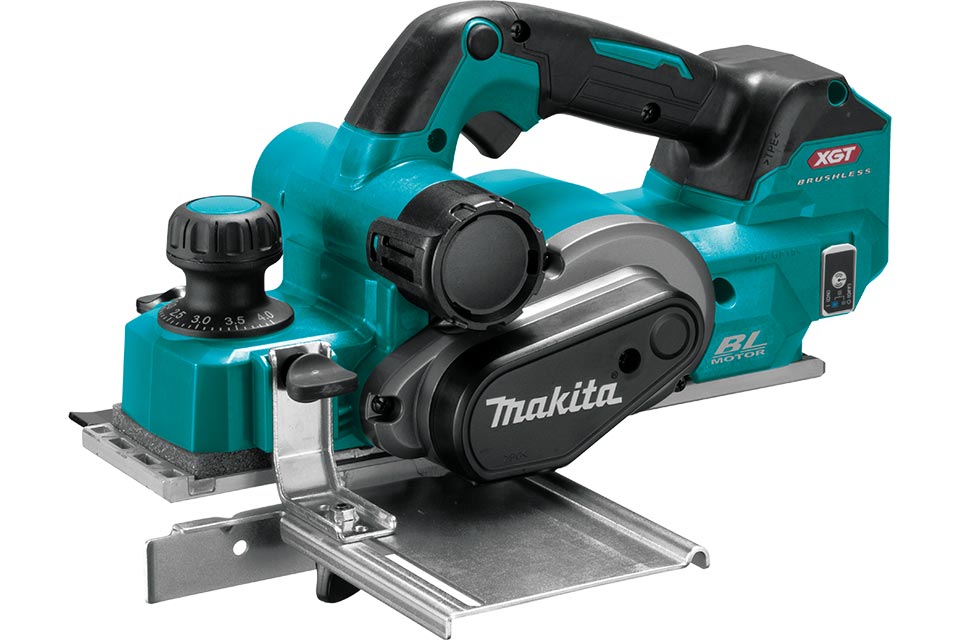
Makita KP001G Cordless Planer 82mm 40V Max Instruction Manual


makita KP001G Cordless Planer 82mm 40V Max

SPECIFICATIONS
| Model: | KP001G |
| Planing width | 82 mm |
| Planing depth | 4 mm |
| Shiplapping depth | 25 mm |
| No load speed | 15,000 min-1 |
| Overall length (with BL4040) | 385 mm |
| Rated voltage | D.C. 36 V – 40 V max |
| Net weight | 3.7 – 4.9 kg |
- Due to our continuing program of research and development, the specifications herein are subject to change without notice.
- Specifications and battery cartridge may differ from country to country.
- The weight may differ depending on the attachment(s), including the battery cartridge. The lightest and heavi-est combinations, according to EPTA-Procedure 01/2014, are shown in the table.
Applicable battery cartridge and charger
| Battery cartridge | BL4020* / BL4025* / BL4040* / BL4050F / BL4080F * : Recommended battery |
| Charger | DC40RA / DC40RB / DC40RC |
Some of the battery cartridges and chargers listed above may not be available depending on your region of residence.
WARNING: Only use the battery cartridges and chargers listed above. Use of any other battery cartridges and chargers may cause injury and/or fire.
Intended use
The tool is intended for planing wood.
Noise
The typical A-weighted noise level determined accord-ing to EN62841-2-14:
Sound pressure level (LpA) : 87 dB(A)
Sound power level (LWA) : 98 dB (A)
Uncertainty (K) : 3 dB(A)
- NOTE: The declared noise emission value(s) has been measured in accordance with a standard test method and may be used for comparing one tool with another.
- NOTE: The declared noise emission value(s) may also be used in a preliminary assessment of exposure.
- WARNING: Wear ear protection.
- WARNING: The noise emission during actual use of the power tool can differ from the declared value(s) depending on the ways in which the tool is used especially what kind of workpiece is processed.
- WARNING: Be sure to identify safety measures to protect the operator that are based on an estimation of exposure in the actual conditions of use (taking account of all parts of the operating cycle such as the times when the tool is switched off and when it is running idle in addition to the trigger time).
Vibration
The vibration total value (tri-axial vector sum) deter-mined according to EN62841-2-14:
Work mode: planing softwood
Vibration emission (ah) : 4.3 m/s2
Uncertainty (K) : 1.5 m/s2
- NOTE: The declared vibration total value(s) has been measured in accordance with a standard test method and may be used for comparing one tool with another.
- NOTE: The declared vibration total value(s) may also be used in a preliminary assessment of exposure.
- WARNING: The vibration emission during actual use of the power tool can differ from the declared value(s) depending on the ways in which the tool is used especially what kind of workpiece is processed.
- WARNING: Be sure to identify safety measures to protect the operator that are based on an estimation of exposure in the actual conditions of use (taking account of all parts of the operating cycle such as the times when the tool is switched off and when it is running idle in addition to the trigger time).
EC Declaration of Conformity
For European countries only
The EC declaration of conformity is included as Annex A to this instruction manual.
SAFETY WARNINGS
General power tool safety warnings
WARNING: Read all safety warnings, instructions, illustrations and specifications provided with this power tool. Failure to follow all instructions listed below may result in electric shock, fire and/or serious injury.
Save all warnings and instructions for future reference.
The term “power tool” in the warnings refers to your mains-operated (corded) power tool or battery-operated (cordless) power tool.
Cordless Planer Safety Warnings
- Wait for the cutter to stop before setting the tool down. An exposed rotating cutter may engage the surface leading to possible loss of control and serious injury.
- Use clamps or another practical way to secure and support the workpiece to a stable plat-form. Holding the workpiece by your hand or against the body leaves it unstable and may lead to loss of control.
- Rags, cloth, cord, string and the like should never be left around the work area.
- Avoid cutting nails. Inspect for and remove all nails from the workpiece before operation.
- Use only sharp blades. Handle the blades very carefully.
- Be sure the blade installation bolts are securely tightened before operation.
- Hold the tool firmly with both hands.
- Keep hands away from rotating parts.
- Before using the tool on an actual workpiece, let it run for a while. Watch for vibration or wobbling that could indicate poor installation or a poorly balanced blade.
- Make sure the blade is not contacting the workpiece before the switch is turned on.
- Wait until the blade attains full speed before cutting.
- Always switch off and wait for the blades to come to a complete stop before adjusting depth of cut.
- Never stick your finger into the chip chute. Chute may jam when cutting damp wood. Clean out chips with a stick.
- Do not leave the tool running. Operate the tool only when hand-held.
- When replace the blades or some parts on the drum, make sure to replace the parts on both sides of the drum as a set. Otherwise, the resulting imbalance will cause vibration and shorten tool life.
- Use only Makita blades specified in this manual.
- Always use the correct dust mask/respirator for the material and application you are working with.
- Operate the tool on stable condition. Operation on unstable condition may cause a damage injury.
SAVE THESE INSTRUCTIONS.
WARNING: DO NOT let comfort or familiarity with product (gained from repeated use) replace strict adherence to safety rules for the subject product.
MISUSE or failure to follow the safety rules stated in this instruction manual may cause serious personal injury.
Important safety instructions for battery cartridge
- Before using battery cartridge, read all instructions and cautionary markings on (1) battery charger, (2) battery, and (3) product using battery.
- Do not disassemble or tamper with the battery cartridge. It may result in a fire, excessive heat, or explosion.
- If operating time has become excessively shorter, stop operating immediately. It may result in a risk of overheating, possible burns and even an explosion.
- If electrolyte gets into your eyes, rinse them out with clear water and seek medical attention right away. It may result in loss of your eyesight.
- Do not short the battery cartridge:
- Do not touch the terminals with any conductive material.
- Avoid storing battery cartridge in a container with other metal objects such as nails, coins, etc.
- Do not expose battery cartridge to water or rain.
A battery short can cause a large current flow, overheating, possible burns and even a breakdown.
- Do not store and use the tool and battery cartridge in locations where the temperature may reach or exceed 50 °C (122 °F).
- Do not incinerate the battery cartridge even if it is severely damaged or is completely worn out. The battery cartridge can explode in a fire.
- Do not nail, cut, crush, throw, drop the battery cartridge, or hit against a hard object to the battery cartridge. Such conduct may result in a fire, excessive heat, or explosion.
- Do not use a damaged battery.
- The contained lithium-ion batteries are subject to the Dangerous Goods Legislation requirements. For commercial transports e.g. by third parties, forwarding agents, special requirement on packaging and labeling must be observed.
For preparation of the item being shipped, consulting an expert for hazardous material is required. Please also observe possibly more detailed national regulations.
Tape or mask off open contacts and pack up the battery in such a manner that it cannot move around in the packaging. - When disposing the battery cartridge, remove it from the tool and dispose of it in a safe place. Follow your local regulations relating to disposal of battery.
- Use the batteries only with the products specified by Makita. Installing the batteries to non-compliant products may result in a fire, excessive heat, explosion, or leak of electrolyte.
- If the tool is not used for a long period of time, the battery must be removed from the tool.
- During and after use, the battery cartridge may take on heat which can cause burns or low temperature burns. Pay attention to the handling of hot battery cartridges.
- Do not touch the terminal of the tool immediately after use as it may get hot enough to cause burns.
- Do not allow chips, dust, or soil stuck into the terminals, holes, and grooves of the battery cartridge. It may cause heating, catching fire, burst and malfunction of the tool or battery cartridge, resulting in burns or personal injury.
- Unless the tool supports the use near high-voltage electrical power lines, do not use the battery cartridge near a high-voltage electrical power lines. It may result in a malfunction or breakdown of the tool or battery cartridge.
- Keep the battery away from children.
SAVE THESE INSTRUCTIONS.
CAUTION: Only use genuine Makita batteries. Use of non-genuine Makita batteries, or batteries that have been altered, may result in the battery bursting causing fires, personal injury and damage. It will also void the Makita warranty for the Makita tool and charger.
Tips for maintaining maximum battery life
- Charge the battery cartridge before completely discharged. Always stop tool operation and charge the battery cartridge when you notice less tool power.
- Never recharge a fully charged battery cartridge. Overcharging shortens the battery service life.
- Charge the battery cartridge with room temperature at 10 °C – 40 °C (50 °F – 104 °F). Let a hot battery cartridge cool down before charging it.
- When not using the battery cartridge, remove it from the tool or the charger.
- Charge the battery cartridge if you do not use it for a long period (more than six months).
Important safety instructions for wireless unit
- Do not disassemble or tamper with the wireless unit.
- Keep the wireless unit away from young children. If accidentally swallowed, seek medical attention immediately.
- Use the wireless unit only with Makita tools.
- Do not expose the wireless unit to rain or wet conditions.
- Do not use the wireless unit in places where the temperature exceeds 50 °C (122 °F).
- Do not operate the wireless unit in places where medical instruments, such as heart pace makers are nearby.
- Do not operate the wireless unit in places where automated devices are nearby. If operated, automated devices may develop malfunction or error.
- Do not operate the wireless unit in places under high temperature or places where static electricity or electrical noise could be generated.
- The wireless unit can produce electromagnetic fields (EMF) but they are not harmful to the user.
- The wireless unit is an accurate instrument. Be careful not to drop or strike the wireless unit.
- Avoid touching the terminal of the wireless unit with bare hands or metallic materials.
- Always remove the battery on the product when installing the wireless unit into it.
- When opening the lid of the slot, avoid the place where dust and water may come into the slot. Always keep the inlet of the slot clean.
- Always insert the wireless unit in the correct direction.
- Do not press the wireless activation button on the wireless unit too hard and/or press the button with an object with a sharp edge.
- Always close the lid of the slot when operating.
- Do not remove the wireless unit from the slot while the power is being supplied to the tool. Doing so may cause a malfunction of the wireless unit.
- Do not remove the sticker on the wireless unit.
- Do not put any sticker on the wireless unit.
- Do not leave the wireless unit in a place where static electricity or electrical noise could be generated.
- Do not leave the wireless unit in a place subject to high heat, such as a car sitting in the sun.
- Do not leave the wireless unit in a dusty or powdery place or in a place corrosive gas could be generated.
- Sudden change of the temperature may bedew the wireless unit. Do not use the wireless unit until the dew is completely dried.
- When cleaning the wireless unit, gently wipe with a dry soft cloth. Do not use benzine, thinner, conductive grease or the like.
- When storing the wireless unit, keep it in the supplied case or a static-free container.
- Do not insert any devices other than Makita wireless unit into the slot on the tool.
- Do not use the tool with the lid of the slot dam-aged. Water, dust, and dirt come into the slot may cause malfunction.
- Do not pull and/or twist the lid of the slot more than necessary. Restore the lid if it comes off from the tool.
- Replace the lid of the slot if it is lost or damaged.
FUNCTIONAL DESCRIPTION
CAUTION: Always be sure that the tool is switched off and the battery cartridge is removed before adjusting or checking function on the tool.
Installing or removing battery cartridge
CAUTION: Always switch off the tool before installing or removing of the battery cartridge.
CAUTION: Hold the tool and the battery cartridge firmly when installing or removing battery cartridge. Failure to hold the tool and the battery cartridge firmly may cause them to slip off your hands and result in damage to the tool and battery cartridge and a personal injury.
Fig.1: 1. Red indicator 2. Button 3. Battery cartridge
To install the battery cartridge, align the tongue on the battery cartridge with the groove in the housing and slip it into place. Insert it all the way until it locks in place with a little click. If you can see the red indicator as shown in the figure, it is not locked completely.

CAUTION: Always install the battery cartridge fully until the red indicator cannot be seen. If not, it may accidentally fall out of the tool, causing injury to you or someone around you.
CAUTION: Do not install the battery cartridge forcibly. If the cartridge does not slide in easily, it is not being inserted correctly.
Tool/battery protection system
The tool is equipped with a tool/battery protection system. This system automatically cuts off power to the motor to extend tool and battery life. The tool will auto-matically stop during operation if the tool or battery is placed under one of the following conditions:
Overload protection
When the tool/battery is operated in a manner that causes it to draw an abnormally high current, the tool automatically stops. In this situation, turn the tool off and stop the application that caused the tool to become overloaded. Then turn the tool on to restart.
Overheat protection
When the tool/battery is overheated, the tool stops automatically. In this situation, let the tool/battery cool before turning the tool on again.
Overdischarge protection
When the battery capacity is not enough, the tool stops automatically. In this case, remove the battery from the tool and charge the battery.
Protections against other causes
Protection system is also designed for other causes that could damage the tool and allows the tool to stop automatically. Take all the following steps to clear the causes, when the tool has been brought to a temporary halt or stop in operation.
- Turn the tool off, and then turn it on again to restart.
- Charge the battery(ies) or replace it/them with recharged battery(ies).
- Let the tool and battery(ies) cool down.
If no improvement can be found by restoring protection system, then contact your local Makita Service Center.
Indicating the remaining battery capacity
Press the check button on the battery cartridge to indi-cate the remaining battery capacity. The indicator lamps light up for a few seconds.
Fig.2: 1. Indicator lamps 2. Check button
NOTE: The first (far left) indicator lamp will blink when the battery protection system works.


Adjusting depth of cut
CAUTION: Always switch off and wait for the blades to come to a complete stop before adjusting depth of cut.
NOTE: When turning the depth adjustment knob, be sure to hold the handle firmly with the other hand.
The cutting depth can be adjusted by turning the depth adjustment knob on the front of the tool. Turn the knob to align the pointer with your desired cutting depth on the depth scale.
Fig.3: 1. Depth adjustment knob 2. Pointer 3. Depth scale

Switch action
- WARNING: Before installing the battery cartridge into the tool, always check to see that the switch trigger actuates properly and returns to the “OFF” position when released.
- WARNING: NEVER defeat the lock-off button by taping down or some other means. A switch with a negated lock-off button may result in unintentional operation and serious personal injury.
- WARNING: NEVER use the tool if it runs when you simply pull the switch trigger without pressing the lock-off button. A switch in need of repair may result in unintentional operation and serious personal injury. Return tool to a Makita service center for proper repairs BEFORE further usage.
- NOTICE: Do not pull the switch trigger hard without pressing in the lock-off button. This can cause switch breakage.
To prevent the switch trigger from being accidentally pulled, the lock-off button is provided. To start the tool, depress and hold the lock-off button, and then pull the switch trigger. Release the switch trigger to stop.
Fig.4: 1. Switch trigger 2. Lock-off button

The foot springs out of the rear base when you lift the tool up from work surfaces to avoid the planer blades touching the workpiece directly. It prevents the planer blades from accidental damages when not in use. The foot springs back into the rear base whenever you place the tool base over work surfaces.
Fig.5: 1. Planer blade 2. Rear base 3. Foot 4. Work surface

If you install the battery cartridge while pulling the switch trigger, the tool does not start. To start the tool, release the switch trigger, and then pull the switch trig-ger again while depressing the lock-off button.
Electronic function
The tool is equipped with the following electronic functions for easy operation.
Electric brake
The tool is equipped with an electric brake. If the tool consistently fails to quickly stop after releasing the switch trigger, have the tool serviced at your local Makita Service Center.
Soft start feature
The soft-start function minimizes start-up shock, and makes the tool start smoothly.
ASSEMBLY
CAUTION: Always be sure that the tool is switched off and the battery cartridge is removed before carrying out any work on the tool.
Box wrench storage
When not in use, store the box wrench as shown in the figure to keep it from being lost.
Fig.6: 1. Box wrench

- CAUTION: Tighten the blade installation bolts carefully when attaching the planer blades to the tool. Always check to see they are tightened securely. A loose installation bolt can be dangerous.
- CAUTION: Handle the planer blades very carefully. Use gloves or rags to protect your fingers or hands when removing and installing the planer blades.
- CAUTION: Use only the Makita wrench pro-vided to remove and install the planer blades. Failure to do so may result in overtightening or insufficient tightening of the installation bolts. This could cause an injury.
- NOTICE: To install planer blades, clean out all chips or foreign matter adhering to the drum or the planer blades. Use planer blades of the same dimensions and weight, otherwise drum oscilla-tion/vibration, causing poor planing action, and tool breakdown will result.
For tool with conventional planer blades
NOTE: A pair of planer blades are assembled in the drum. Repeat the following procedures for each planer blade.
Removing conventional planer blades
- Unscrew the installation bolts from the drum using the box wrench provided.
- Disassemble the drum plate and conventional planer blade (with adjusting plate) from the drum.
Fig.7: 1. Installation bolt 2. Drum plate 3. Conventional planer blade (with adjusting plate) 4. Drum - Untighten the screws from the conventional planer blade, and then remove the adjusting plate.
Fig.8: 1. Screws 2. Conventional planer blade 3. Adjusting plate


Installing conventional planer blades
- Set a conventional planer blade onto the blade gauge, aligning its cutting edge along the guide wall on the blade gauge horizontally.
Fig.9: 1. Conventional planer blade 2. Blade gauge 3. Cutting edge 4. Guide wall - Place the adjusting plate over the conventional planer blade, and then slightly tighten the screws.
- Push the adjusting plate forwards until its position-ing guide neatly and entirely fits along the rear side wall of the blade gauge.
- Hold the adjusting plate where it is and tighten the screws to secure it in place.|
Fig.10: 1. Adjusting plate 2. Conventional planer blade 3. Screw 4. Positioning guide 5. Rear side wall 6. Blade gauge - Clean out all the wood chips and foreign matters adhering to the drum and conventional planer blade.
- Slip the positioning guide of the adjusting plate into the guide groove in the drum, and then place the drum plate over the conventional planer blade (with adjusting plate)
- Cross-tighten all the installation bolts evenly with the box wrench.
Fig.11: 1. Positioning guide 2. Adjusting plate 3. Guide groove 4. Drum 5. Drum plate 6. Conventional planer blade 7. Installation bolt


For tool with mini planer blades
NOTE: A pair of planer blades are assembled in the drum. Repeat the following procedures for each planer blade.
Removing mini planer blades
- Loosen the installation bolts one turn using the box wrench provided.
Fig.12: 1. Installation bolt 2. Box wrench - Slide the mini planer blade out of the drum by pushing one end of the blade outwards from the belt cover side.
Fig.13: 1. Mini planer blade 2. Drum 3. Belt cover 4. T- handle of box wrench


Installing mini planer blades
- Clean out all the wood chips and foreign matters adhering to the drum and mini planer blade.
- Slide a mini planer blade along between the drum and set plate by pushing one end of the blade inwards from the side opposite to the belt cover.
- Cross-tighten all the installation bolts evenly with the box wrench.
Fig.14: 1. Mini planer blade 2. Drum 3. Set plate 4. Belt cover 5. Installation bolt 6. Box wrench

Mini planer blade calibration
Perform a calibration on planner blades at regular intervals to optimize work efficiency.
- Loosen the installation bolts one turn using the box wrench provided.
- Slide the mini planer blade out of the drum by pushing one end of the blade outwards from the belt cover side.
- Unscrew the installation bolts from the drum using the box wrench.
- Disassemble the drum plate and set plate (with adjusting plate) from the drum.
Fig.15: 1. Installation bolt 2. Drum plate 3. Set plate (with adjusting plate) 4. Drum - Loosen the screws on the set plate one turn to disengage the adjusting plate.
Fig.16: 1. Screws 2. Set plate 3. Adjusting plate - Clean out all the wood chips and foreign matters adhering to the set plate (with adjusting plate) and mini planer blade.
- Set the mini planer blade onto the blade gauge, aligning its cutting edge along the guide wall on the blade gauge horizontally.
- Place the set plate (with adjusting plate) over the mini planer blade, aligning the guide ridges on the set plate with guide grooves on the mini planer blade.
Fig.17: 1. Mini planer blade 2. Blade gauge 3. Cutting edge 4. Guide wall 5. Set plate (with adjusting plate) 6. Guide ridge 7. Guide groove - Push the adjusting plate forwards until its position-ing guide neatly and entirely fits along the rear side wall of the blade gauge.
- Hold the adjusting plate where it is and tighten the screws to secure it in place.
Fig.18: 1. Adjusting plate 2. Set plate 3. Screw 4. Positioning guide 5. Rear side wall 6. Blade gauge - Slip the positioning guide of the adjusting plate into the guide groove in the drum, and then place the drum plate over the set plate (with adjusting plate).
Fig.19: 1. Positioning guide 2. Adjusting plate 3. Guide groove 4. Drum 5. Drum plate 6. Set plate 7. Installation bolt - Slightly tighten the installation bolts, and slide the mini planer blade along between the drum and set plate by pushing one end of the blade inwards from the side opposite to the belt cover.
- Cross-tighten all the installation bolts evenly with the box wrench.
Fig.20: 1. Mini planer blade 2. Drum 3. Set plate 4. Belt cover 5. Installation bolt 6. Box wrench


Planer blade settings
Your planing surface will end up rough and uneven, unless the planer blades are set properly and securely.
Install planer blades correctly so the cutting edges sit in a right angle, on an absolute level with the rear baseline, and exactly parallel to the sole of the plane. Read the examples in the table for proper settings.

Installing guide rule
- Lay the tool down with the belt cover facing upwards.
- Mount the guide rule in place by securing it with the thumb screw into the mounting hole on side of the tool head.
Fig.21: 1. Belt cover 2. Guide rule 3. Thumb screw 4. Mounting hole - Slide the edge fence in and out to your desired planing width, and then tighten the thumb screw to secure it in the required position.
Fig.22: 1. Edge fence 2. Thumb screw


Installing depth guide
- Lay the tool down with the belt cover facing downwards.
- Mount the depth guide in place by securing it with the washer and thumb screw into the mounting hole on side of the tool head.
Fig.23: 1. Belt cover 2. Depth guide 3. Washer 4. Thumb screw 5. Mounting hole - Slide the depth guide up and down to your desired planing depth, and then tighten the thumb screw to secure it in the required position.
Fig.24: 1. Depth guide 2. Thumb screw


Installing chamfering rules
Optional accessory
- Lay the tool down with the front base facing upwards.
- Attach the edge fences to the mounting arms, aligning the projections on the arms with the guide slits in the edge fences, and secure them with the washers and thumb screws.
- Mount the chamfering rules (sets of edge fences and mounting arms) in place by securing them with the thumb screws into the mounting holes on both sides of the tool head.
Fig.25: 1. Front base 2. Edge fence 3. Mounting arm 4. Projection 5. Guide slit 6. Washer 7. Thumb screw 8. Mounting hole - Slide the edge fences in and out to your desired chamfering range, and then tighten the thumb screws to secure them in the required position.
Fig.26: 1. Edge fence 2. Thumb screw


Dust and wood chip extraction
Dust and wood chip can be released from either left or right side of discharge openings. Cover one of the discharge openings on the side opposed to your preferred dust extraction direction with the stopper.
To detach the stopper from the discharge opening, turn the stopper towards the handle slightly to disengage the lock, and then pull it apart.
Fig.27: 1. Stopper 2. Handle

As for installation, insert the stopper straight into one of the openings aligning the locking slot in the stopper with the guide projection on the opening until it locks in place.
Fig.28: 1. Stopper 2. Locking slot 3. Guide projection

Optional accessory
Attach the dust bag onto one of the discharge openings and push firmly as far as it will go. Make sure the dust bag is securely placed over the tapered opening so as not to come off during operation.
Fig.29: 1. Dust bag 2. Discharge opening
Fig.30: 1. Fastener


Connecting a vacuum cleaner
When you wish to perform clean planing operation, connect a Makita vacuum cleaner to your tool. Connect a hose of the vacuum cleaner to one of the discharge openings as shown in the figure.
Fig.31: 1. Vacuum cleaner

Optional accessory
Use a dust extractor elbow to condense extraction air flow at preferred angles for cleaner working environment. Attach the elbow into one of the discharge openings and push firmly as far as it will go.
Fig.32: 1. Elbow

OPERATION
CAUTION: Hold the tool firmly with one hand on the switch handle and the other hand on the depth adjustment knob when operating the tool.
Planing operation
- Hold the tool firmly with your both hands, one hand on the switch handle and the other on the depth adjustment knob.
- Place the front base of the tool flat upon the workpiece surface without the planer blades making any contact.
- Turn the tool on and wait until it attains full speed.
- Gently move the tool forwards, applying slightly more downwards pressure on the depth adjustment knob at the start so as to keep the entire planer base level and even with the workpiece surface.
Fig.33 - Use care to apply pressure evenly over the work-piece surface in the middle of operation, and push the tool steadily forwards.
Fig.34 - Apply greater control on the switch handle to avoid overreaching at the end of a pass since the front base will drop off the workpiece surface.
Fig.35
NOTE: Planing can be easier if you position the workpiece at a slight forward tilt so you ease up on the pressure to hold the tool during operation.
NOTE: Adjust the cutting speed and depth for your desired surface finishes.
For rough finish, set the cutting depth sufficiently deep enough on workpiece.
For neat and fine finish, push the tool slowly with shallow cutting depth and make more passes.


Shiplapping (Rabbeting)
Fig.36
- Install the guide rule and depth guide in the tool and secure them with the washers and thumb screws.
- Adjust the depth guide to the shiplapping depth and secure it in place with the thumb screw.
- Draw a cutting line on the workpiece and align the blade edge with the cutting line.
Fig.37: 1. Blade edge 2. Cutting line 3. Depth guide 4. Thumb screw
* You can opt to let the blade end come out of the side end of the front base by 0.2 mm – 0.4 mm. (See “B” in the following figure.)
Fig.38: 1. Blade edge 2. Side end of drum 3. Side end of front base - Slide the edge fence in the guide rule inwards until it comes in contact with the side wall of the workpiece. Then secure it in place with the thumb screw.
Fig.39: 1. Guide rule 2. Edge fence 3. Side wall 4. Thumb screw - Perform planning operation by moving the tool with the whole edge fence sliding along the side wall of the workpiece.
NOTE: Reaching lengths of the guide fence can be extended by attaching an extra piece of wood to the attachment holes in the guide fence.
Fig.40: 1. Extra piece of wood 2. Attachment holes


Chamfering
Fig.41
Perform planning operation by moving the tool aligning one of the three “V” grooves in the front base with the corner edge of the workpiece.
Fig.42: 1. V groove for medium chamfers 2. V groove for small chamfers 3. V groove for large chamfers

Optional accessory
- Slide the edge fences in the chamfering rules inwards until they come in contact with the corner walls of the workpiece.
- Secure the edge fences in place with the thumb screws.
- Perform planning operation by moving the tool with the whole edge fences sliding along the corner walls of the workpiece.
Fig.43: 1. Chamfering rule 2. Edge fences 3. Thumb screw
Fig.44: 1. Edge fences 2. Small chamfering 3. Large chamfering
WIRELESS ACTIVATION FUNCTION
What you can do with the wireless activation function
The wireless activation function enables clean and comfortable operation. By connecting a supported vacuum cleaner to the tool, you can run the vacuum cleaner automatically along with the switch operation of the tool.
Fig.45

- A wireless unit (optional accessory)
- A vacuum cleaner which supports the wireless activation function
The overview of the wireless activation function setting is as follows. Refer to each section for detail procedures.
- Installing the wireless unit
- Tool registration for the vacuum cleaner
- Starting the wireless activation function
Installing the wireless unit
Optional accessory
CAUTION: Place the tool on a flat and stable surface when installing the wireless unit.NOTICE: Clean the dust and dirt on the tool before installing the wireless unit. Dust or dirt may cause malfunction if it comes into the slot of the wireless unit.
NOTICE: To prevent the malfunction caused by static, touch a static discharging material, such as a metal part of the tool, before picking up the wireless unit.
NOTICE: When installing the wireless unit, always be sure that the wireless unit is inserted in the correct direction and the lid is completely closed.
- Open the lid on the tool as shown in the figure.
Fig.46: 1. Lid - Insert the wireless unit to the slot and then close the lid.
When inserting the wireless unit, align the projections with the recessed portions on the slot.
Fig.47: 1. Wireless unit 2. Projection 3. Lid 4. Recessed portion
Fig.48: 1. Wireless unit 2. Hook 3. Lid
NOTICE: Always use the hooks on the back of the lid when removing the wireless unit. If the hooks do not catch the wireless unit, close the lid completely and open it slowly again.


Tool registration for the vacuum cleaner
- NOTE: A Makita vacuum cleaner supporting the wireless activation function is required for the tool registration.
- NOTE: Finish installing the wireless unit to the tool before starting the tool registration.
- NOTE: During the tool registration, do not pull the switch trigger or turn on the power switch on the vacuum cleaner.
- NOTE: Refer to the instruction manual of the vacuum cleaner, too.
If you wish to activate the vacuum cleaner along with the switch operation of the tool, finish the tool registration beforehand.
- Install the batteries to the vacuum cleaner and the tool.
- Set the stand-by switch on the vacuum cleaner to “AUTO”.
Fig.49: 1. Stand-by switch - Press the wireless activation button on the vacuum cleaner for 3 seconds until the wireless activation lamp blinks in green. And then press the wireless acti-vation button on the tool in the same way.
Fig.50: 1. Wireless activation button 2. Wireless activation lamp
NOTE: The wireless activation lamps finish blinking in green after 20 seconds elapsed. Press the wireless activation button on the tool while the wireless activation lamp on the cleaner is blinking. If the wireless activation lamp does not blink in green, push the wire-less activation button briefly and hold it down again.
NOTE: When performing two or more tool registrations for one vacuum cleaner, finish the tool registration one by one.


Starting the wireless activation function
NOTE: Finish the tool registration for the vacuum cleaner prior to the wireless activation.
NOTE: Refer to the instruction manual of the vacuum cleaner, too.
After registering a tool to the vacuum cleaner, the vacuum cleaner will automatically runs along with the switch operation of the tool.
- Install the wireless unit to the tool.
- Connect the hose of the vacuum cleaner with the tool.
Fig.51 - Set the stand-by switch on the vacuum cleaner to “AUTO”.
Fig.52: 1. Stand-by switch - Push the wireless activation button on the tool briefly. The wireless activation lamp will blink in blue.
Fig.53: 1. Wireless activation button 2. Wireless activation lamp - Turn on the tool. Check if the vacuum cleaner runs while the tool is operating.
To stop the wireless activation of the vacuum cleaner, push the wireless activation button on the tool.


- NOTE: The wireless activation lamp on the tool will stop blinking in blue when there is no operation for 2 hours. In this case, set the standby switch on the vacuum cleaner to “AUTO” and push the wireless activation button on the tool again.
- NOTE: The vacuum cleaner starts/stops with a delay. There is a time lag when the vacuum cleaner detects a switch operation of the tool.
- NOTE: The transmission distance of the wireless unit may vary depending on the location and surrounding circumstances.
- NOTE: When two or more tools are registered to one vacuum cleaner, the vacuum cleaner may start running even if you do not turn on your tool because another user is using the wireless activation function.
Description of the wireless activation lamp status
Fig.54: 1. Wireless activation lamp

| Status | Wireless activation lamp | Description | |||
| Color | On |
Blinking |
Duration | ||
| Standby | Blue | 2 hours | The wireless activation of the vacuum cleaner is available. The lamp will automatically turn off when no operation is performed for 2 hours. | ||
| When the tool is running. | The wireless activation of the vacuum cleaner is available and the tool is running. | ||||
| Tool registration | Green | 20 seconds | Ready for the tool registration. Waiting for the registration by the vacuum cleaner. | ||
| 2 seconds | The tool registration has been finished. The wireless activation lamp will start blinking in blue. | ||||
| Cancelling tool registration | Red | 20 seconds | Ready for the cancellation of the tool registration. Waiting for the cancellation by the vacuum cleaner. | ||
| 2 seconds | The cancellation of the tool registration has been finished. The wireless activation lamp will start blinking in blue. | ||||
| Others | Red | 3 seconds | The power is supplied to the wireless unit and the wireless activation function is starting up. | ||
| Off | – | – | The wireless activation of the vacuum cleaner is stopped. | ||


Cancelling tool registration for the vacuum cleaner
Perform the following procedure when cancelling the tool registration for the vacuum cleaner.
- Install the batteries to the vacuum cleaner and the tool.
- Set the stand-by switch on the vacuum cleaner to “AUTO”.
Fig.55: 1. Stand-by switch - Press the wireless activation button on the vacuum cleaner for 6 seconds. The wireless activation lamp blinks in green and then become red. After that, press the wireless activation button on the tool in the same way.
Fig.56: 1. Wireless activation button 2. Wireless activation lamp


NOTE: The wireless activation lamps finish blinking in red after 20 seconds elapsed. Press the wireless activation button on the tool while the wireless activation lamp on the cleaner is blinking. If the wireless activation lamp does not blink in red, push the wireless activation button briefly and hold it down again.
Troubleshooting for wireless activation function
Before asking for repairs, conduct your own inspection first. If you find a problem that is not explained in the manual, do not attempt to dismantle the tool. Instead, ask Makita Authorized Service Centers, always using Makita replace-ment parts for repairs.
| State of abnormality | Probable cause (malfunction) | Remedy |
| The wireless activation lamp does not light/blink. |
The wireless unit is not installed into the tool. The wireless unit is improperly installed into the tool. | Install the wireless unit correctly. |
| The terminal of the wireless unit and/or the slot is dirty. | Gently wipe off dust and dirt on the terminal of the wireless unit and clean the slot. | |
| The wireless activation button on the tool has not been pushed. | Push the wireless activation button on the tool briefly. | |
| The stand-by switch on the vacuum cleaner is not set to “AUTO”. | Set the stand-by switch on the vacuum cleaner to “AUTO”. | |
| No power supply | Supply the power to the tool and the vacuum cleaner. | |
| Cannot finish tool registration / can- celling tool registration successfully. | The wireless unit is not installed into the tool. The wireless unit is improperly installed into the tool. | Install the wireless unit correctly. |
| The terminal of the wireless unit and/or the slot is dirty. | Gently wipe off dust and dirt on the terminal of the wireless unit and clean the slot. | |
| The stand-by switch on the vacuum cleaner is not set to “AUTO”. | Set the stand-by switch on the vacuum cleaner to “AUTO”. | |
| No power supply | Supply the power to the tool and the vacuum cleaner. | |
| Incorrect operation | Push the wireless activation button briefly and perform the tool registration/cancellation procedures again. | |
| The tool and vacuum cleaner are away from each other (out of the transmission range). | Get the tool and vacuum cleaner closer to each other. The maximum transmission distance is approximately 10 m however it may vary according to the circumstances. | |
| Before finishing the tool registration/cancellation; – the switch of the tool is turned on or; – the power button on the vacuum cleaner is turned on. |
Push the wireless activation button briefly and perform the tool registration/cancellation procedures again. | |
| The tool registration procedures for the tool or vacuum cleaner have not finished. |
Perform the tool registration procedures for both the tool and the vacuum cleaner at the same timing. | |
| Radio disturbance by other appliances which generate high-intensity radio waves. | Keep the tool and vacuum cleaner away from the appliances such as Wi-Fi devices and microwave ovens. | |
| The vacuum cleaner does not run along with the switch operation of the tool. | The wireless unit is not installed into the tool. The wireless unit is improperly installed into the tool. | Install the wireless unit correctly. |
| The terminal of the wireless unit and/or the slot is dirty. | Gently wipe off dust and dirt on the terminal of the wireless unit and clean the slot. | |
| The wireless activation button on the tool has not been pushed. | Push the wireless activation button briefly and make sure that the wireless activation lamp is blinking in blue. | |
| The stand-by switch on the vacuum cleaner is not set to “AUTO”. | Set the stand-by switch on the vacuum cleaner to “AUTO”. | |
| More than 10 tools are registered to the vacuum cleaner. | Perform the tool registration again. If more than 10 tools are registered to the vacuum cleaner, the tool registered earliest will be cancelled automatically. | |
| The vacuum cleaner erased all tool registrations. | Perform the tool registration again. | |
| No power supply | Supply the power to the tool and the vacuum cleaner. | |
| The tool and vacuum cleaner are away from each other (out of the transmission range). | Get the tool and vacuum cleaner closer each other. The maximum transmission distance is approximately 10 m however it may vary according to the circumstances. | |
| Radio disturbance by other appliances which generate high-intensity radio waves. | Keep the tool and vacuum cleaner away from the appliances such as Wi-Fi devices and microwave ovens. | |
| The vacuum cleaner runs while the tool is not operating. | Other users are using the wireless activation of the vacuum cleaner with their tools. | Turn off the wireless activation button of the other tools or cancel the tool registration of the other tools. |
MAINTENANCE
CAUTION: Always be sure that the tool is switched off and the battery cartridge is removed before attempting to perform inspection or maintenance.
NOTICE: Never use gasoline, benzine, thinner, alcohol or the like. Discoloration, deformation or cracks may result.
To maintain product SAFETY and RELIABILITY, repairs, any other maintenance or adjustment should be performed by Makita Authorized or Factory Service Centers, always using Makita replacement parts.
Cleaning up chip discharge openings
Clean the chip discharge openings regularly.
Use a compressed air to clean the clogged chip dis-charge openings.
Sharpening blades
For conventional planer blades only
Always keep your planer blades sharp for the best performance. Use the sharpening holder (optional accessory) to refine the planer blade edges safely and effectively.
Fig.57: 1. Sharpening holder 2. Blade

- Loosen the two wing nuts in the sharpening holder.
- Slip the back ends of the planer blades into the mounting slots as far as they will go with the cutting edges to be sharpened facing downwards.
Fig.58: 1. Sharpening holder 2. Wing nut 3. Blades 4. Cutting edges 5. Mounting slots 6. Bolt head - Tighten the wing nuts to secure the planer blades in place.
- Soak a dressing stone in water for 2 or 3 minutes before sharpening.
- Hold the sharpening holder firmly, and gently place the cutting edges over the surface of the dressing stone.
- Sharpen the cutting edges by moving the sharpen-ing holder back and forwards.
Fig.59

OPTIONAL ACCESSORIES
CAUTION: These accessories or attachments are recommended for use with your Makita tool specified in this manual. The use of any other accessories or attachments might present a risk of injury to persons. Only use accessory or attachment for its stated purpose.
If you need any assistance for more details regarding these accessories, ask your local Makita Service Center.
- High-speed steel Planer blade
- Tungsten-carbide Planer blade (For longer blade life)
- Mini planer blade
- Sharpening holder assembly
- Blade gauge assembly
- Set plate set
- Guide rule assembly
- Dressing stone
- Dust bag assembly
- Elbow
- Chamfering rule assembly
- Wireless unit
- Makita genuine battery and charger
NOTE: Some items in the list may be included in the tool package as standard accessories. They may differ from country to country.
Makita Europe N.V.
Jan-Baptist Vinkstraat 2,
3070 Kortenberg, Belgium