Makita DUR368A Cordless Grass Trimmer Instruction Manual
makita DUR368A Cordless Grass Trimmer Instruction Manual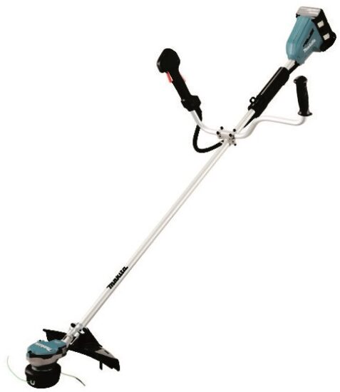


SPECIFICATIONS
| Model: | DUR368A | DUR368L | |
| Handle type | Bike handle | Loop handle | |
| No load speed (at each rotation speed level) |
Cutter blade / Nylon cutting head / Plastic blade | 3: 6,500 min-1 2: 5,300 min-1 1: 3,500 min-1 | |
| Overall length (without cutting tool) | 1,758 mm | ||
| Nylon cord diameter | 2.0 – 2.4 mm | ||
| Applicable cutting tool and cutting diameter | 3-tooth blade (P/N: 195298-3) | 230 mm | |
| 4-tooth blade (P/N: B-14118) | 230 mm | ||
| 8-tooth blade (P/N: B-14130) | 230 mm | ||
| Nylon cutting head (P/N: 198893-8) | 350 mm | ||
| Plastic blade (P/N: 198383-1) | 255 mm | ||
| Rated voltage | D.C. 36 V | ||
| Net weight | 4.1 – 4.7 kg | 3.9 – 4.5 kg | |
- Due to our continuing program of research and development, the specifications herein are subject to change without notice.
- Specifications may differ from country to country.
- The weight may differ depending on the attachment(s), including the battery cartridge. The lightest and heaviest combination, according to EPTA-Procedure 01/2014, are shown in the table.
Applicable battery cartridge, battery adapter and charger
| Battery cartridge | BL1815N / BL1820B / BL1830B / BL1840B / BL1850B / BL1860B |
| Battery adapter | BAP182 / BL36120A |
| Charger | DC18RC / DC18RD / DC18RE / DC18SD / DC18SE / DC18SF / DC18SH |
Some of the battery cartridges, battery adapters and chargers listed above may not be available depending on your region of residence.
WARNING: Only use the battery cartridges, battery adapters and chargers listed above. Use of any other battery cartridges,battery adapters and chargers may cause injury and/or fire.
Noise
Applicable standard : ISO22868
Model DUR368A
| Cutting tool | Sound pressure level (LPA) dB(A) | Sound power level (LWA) dB(A) | ||
| LPA dB(A) | Uncertainty (K) dB(A) | LWA dB(A) | Uncertainty (K) dB(A) | |
| 4-tooth blade | 74.7 | 1.0 | 89.2 | 1.6 |
| Nylon cutting head | 76.4 | 1.6 | 89 | 1.0 |
| Plastic blade | 75.1 | 0.3 | 86 | 0.4 |
Model DUR368L
| Cutting tool | Sound pressure level (LPA) dB(A) | Sound power level (LWA) dB(A) | ||
| LPA dB(A) | Uncertainty (K) dB(A) | LWA dB(A) | Uncertainty (K) dB(A) | |
| 4-tooth blade | 74.7 | 1.0 | 89.2 | 1.6 |
| Nylon cutting head | 76.4 | 1.6 | 89 | 1.0 |
| Plastic blade | 75.1 | 0.3 | 86 | 0.4 |
Even if the sound pressure level listed above is 80 dB (A) or less, the level under working may exceed 80 dB (A). Wear ear protection.
NOTE: The declared noise emission value(s) has been measured in accordance with a standard test method and may be used for comparing one tool with another.
NOTE: The declared noise emission value(s) may also be used in a preliminary assessment of exposure.

Vibration
Applicable standard : ISO22867
Model DUR368A
| Cutting tool | Left hand | Right hand | ||
| ah,W (m/s2) | Uncertainty K (m/s2) | ah,W (m/s2) | Uncertainty K (m/s2) | |
| 4-tooth blade | 2.5 | 1.5 | 2.5 | 1.5 |
| Nylon cutting head | 2.5 | 1.5 | 2.5 | 1.5 |
| Plastic blade | 2.5 | 1.5 | 2.5 | 1.5 |
Model DUR368L
| Cutting tool | Left hand | Right hand | ||
| ah,W (m/s2) | Uncertainty K (m/s2) | ah,W (m/s2) | Uncertainty K (m/s2) | |
| 4-tooth blade | 2.5 | 1.5 | 2.5 | 1.5 |
| Nylon cutting head | 2.5 | 1.5 | 2.5 | 1.5 |
| Plastic blade | 2.5 | 1.5 | 2.5 | 1.5 |
NOTE: The declared vibration total value(s) has been measured in accordance with a standard test method and may be used for comparing one tool with another.
NOTE: The declared vibration total value(s) may also be used in a preliminary assessment of exposure.
Symbols
The followings show the symbols which may be used for the equipment. Be sure that you understand their meaning before use.


gloves
Steeltoed safety boots are recommended.


Only for EU countries
Do not dispose of electric equipment or battery pack together with household waste material! In observance of the European Directives, on Waste Electric and Electronic Equipment and Batteries and Accumulators and Waste Batteries and Accumulators and their implementation in accordance with national laws, electric equipment and batteries and battery pack(s) that have reached the end of their life must be collected separately and returned to an environmentally compatible recycling facility.

EC Declaration of Conformity
For European countries only
The EC declaration of conformity is included as Annex A to this instruction manual.
SAFETY WARNINGS
General power tool safety warnings
WARNING: Read all safety warnings, instructions, illustrations and specifications provided with this power tool. Failure to follow all instructions listed below may result in electric shock, fire and/or serious injury.
Save all warnings and instructions for future reference.
The term “power tool” in the warnings refers to your mains-operated (corded) power tool or battery-operated (cordless) power tool.
Important safety instructions for the tool
Save all warnings and instructions for future reference.
Intended use
This tool is only intended for cutting grass, weeds, bushes and undergrowth. It should not be used for any other purpose such as edging or hedge cutting as this may cause injury.
General instructions
- Never allow people unfamiliar with these instructions, people (including children) with reduced physical, sensory or mental capabilities, or lack of experience and knowledge to use the tool. Children should be supervised to ensure that they do not play with the tool.
- Before starting the tool, read this instruction manual to become familiar with the handling of the tool.
- Do not lend the tool to a person with insufficient experience or knowledge regarding handling of brushcutters and string trimmers.
- When lending the tool, always attach this instruction manual.
- Handle the tool with the utmost care and attention.
- Never use the tool after consuming alcohol or drugs, or if feeling tired or ill.
- Never attempt to modify the tool.
- Follow the regulations about handling of brushcutters and string trimmers in your country.
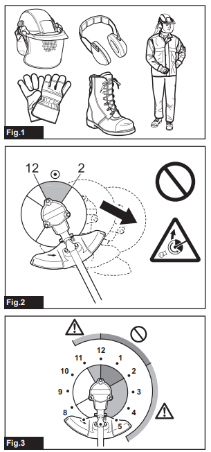
Personal protective equipment
Fig.1
- Wear safety helmet, protective goggles and protective gloves to protect yourself from flying debris or falling objects.
Wear ear protection such as ear muffs to prevent hearing loss. - Wear proper clothing and shoes for safe operation, such as a work overall and sturdy, non-slip shoes. Do not wear loose clothing or jewelry. Loose clothes, jewelry or long hair can be caught in moving parts.
- When touching the cutting blade, wear protective gloves. Cutting blades can cut bare hands severely.
Work area safety
- Operate the tool under good visibility and daylight conditions only. Do not operate the tool in darkness or fog.
- Do not operate the tool in explosive atmospheres, such as in the presence of flammable liquids, gases or dust. The tool creates sparks which may ignite the dust or fumes.
- During operation, never stand on an unstable or slippery surface or a steep slope. During the cold season, beware of ice and snow and always ensure secure footing.
- During operation, keep bystanders or animals at least 15 m away from the tool. Stop the tool as soon as someone approaches.
- Never operate the tool while people, especially children, or pets are nearby.
- Before operation, examine the work area for stones or other solid objects. They can be thrown or cause dangerous kickback and result in serious injury and/or property damage.
Electrical and battery safety
- Do not expose the tool to rain or wet conditions. Water entering the tool will increase the risk of electric shock.
- Do not use the tool if the switch does not turn it on and off. Any tool that cannot be controlled with the switch is dangerous and must be repaired.
- Prevent unintentional starting. Ensure the switch is in the off-position before installing a battery pack, picking up or carrying the tool. Carrying the tool with your finger on the switch or energising the tool that have the switch on invites accidents.
- Do not dispose of the battery(ies) in a fire. The cell may explode. Check with local codes for possible special disposal instructions.
- Do not open or mutilate the battery(ies). Released electrolyte is corrosive and may cause damage to the eyes or skin. It may be toxic if swallowed.
- Do not charge battery in rain, or in wet locations.
Putting into operation
- Before assembling or adjusting the tool, remove the battery cartridge.
- Before handling the cutter blade, wear protective gloves.
- Before installing the battery cartridge, inspect the tool for damages, loose screws/nuts or improper assembly. Sharpen blunt cutter blade. If the cutter blade is bent or damaged, replace it. Check all control levers and switches for easy action. Clean and dry the handles.
- Never attempt to switch on the tool if it is damaged or not fully assembled. Otherwise serious injury may result.
- Adjust the shoulder harness and hand grip to suit the operator’s body size.
- When inserting a battery cartridge, keep the cutting attachment clear of your body and other object, including the ground. It may rotate when starting and may cause injury or damage to the tool and/or property.
- Remove any adjusting key, wrench or blade cover before turning the tool on. An accessory left attached to a rotating part of the tool may result in personal injury.
- The cutting tool has to be equipped with the guard. Never run the tool with damaged guards or without guards in place!
- Make sure there are no electrical cables, water pipes, gas pipes etc. that could cause a hazard if damaged by use of the tool.
Operation
- In the event of an emergency, switch off the tool immediately.
- If you feel any unusual condition (e.g. noise, vibration) during operation, switch off the tool and remove the battery cartridge. Do not use the tool until the cause is recognized and solved.
- The cutting attachment continues to rotate for a short period after turning the tool off. Don’t rush to contact the cutting attachment.
- During operation, use the shoulder harness.
Keep the tool on your right side firmly. - Do not overreach. Keep proper footing and balance at all times. Watch for hidden obstacles such as tree stumps, roots and ditches to avoid stumbling.
- Always be sure of your footing on slopes.
- Walk, never run.
- Never work on a ladder or tree to avoid loss of control.
- If the tool gets heavy impact or fall, check the condition before continuing work. Check the controls and safety devices for malfunction. If there is any damage or doubt, ask our authorized service center for the inspection and repair.
- Take a rest to prevent loss of control caused by fatigue. We recommend taking a 10 to 20-minute rest every hour.
- When you leave the tool, even if it is a short time, always remove the battery cartridge. The unattended tool with the battery cartridge installed may be used by unauthorized person and cause serious accident.
- If grass or branches get caught between the cutting attachment and guard, always turn the tool off and remove the battery cartridge before cleaning. Otherwise the cutting attachment may rotate unintentionally and cause serious injury.
- Never touch moving hazardous parts before the moving hazardous parts have come to a complete stop and the battery cartridge is removed.
- If the cutting attachment hits stones or other hard objects, immediately turn the tool off.
Then remove the battery cartridge and inspect the cutting attachment. - Check the cutting attachment frequently during operation for cracks or damages. Before the inspection, remove the battery cartridge and wait until the cutting attachment stops completely. Replace damaged cutting attachment immediately, even if it has only superficial cracks.
- Never cut above waist height.
- Before starting the cutting operation, wait until the cutting attachment reaches a constant speed after turning the tool on.
- When using a cutting blade, swing the tool evenly in half-circle from right to left, like using a scythe.
- Hold the tool by insulated gripping surfaces only, because the cutter blade may contact hidden wiring. Cutter blades contacting a “live” wire may make exposed metal parts of the tool “live” and could give the operator an electric shock.
- Do not start the tool when the cutting tool is tangled with cut grass.
- Before starting the tool, be sure that the cutting tool is not touching the ground and other obstacles such as a tree.
- During operation always hold the tool with both hands. Never hold the tool with one hand during use.
- Do not operate the tool in bad weather or if there is a risk of lightning.
Cutting tools
- Do not use a cutting tool which is not recommended by us.
- Use an applicable cutting attachment for the job in hand.
- Nylon cutting heads (string trimmer heads) and plastic blades are suitable for trimming lawn grass.
- Cutting blades are suitable for cutting weeds, high grasses, bushes, shrubs, underwood, thicket, and the like.
- Never use other blades including metal multi-piece pivoting chains and flail blades. It may result in serious injury.
- Only use the cutting tool that are marked with a speed equal or higher than the speed marked on the tool.
- Always keep your hands, face, and clothes away from the cutting tool when it is rotating. Failure to do so may cause personal injury.
- Always use the cutting attachment guard properly suited for the cutting attachment used.
- When using cutting blades, avoid kickback and always prepare for an accidental kickback. See the section for Kickback.
- When not in use, attach the blade cover onto the blade. Remove the cover before operation.
Kickback (Blade thrust)
- Kickback (blade thrust) is a sudden reaction to a caught or bound cutting blade. Once it occurs, the tool is thrown sideway or toward the operator at great force and it may cause serious injury.
- Kickback occurs particularly when applying the blade segment between 12 and 2 o’clock to solids, bushes and trees with 3 cm or larger diameter.
- To avoid kickback:
- Apply the segment between 8 and 11 o’clock.
- Never apply the segment between 12 and 2 o’clock.
- Never apply the segment between 11 and 12 o’clock and between 2 and 5 o’clock, unless the operator is well trained and experienced and does it at his/her own risk.
- Never use cutting blades close to solids, such as fences, walls, tree trunks and stones.
- Never use cutting blades vertically, for such operations as edging and trimming hedges.
Fig.3
Vibration
- People with poor circulation who are exposed to excessive vibration may experience injury to blood vessels or the nervous system. Vibration may cause the following symptoms to occur in the fingers, hands or wrists: “Falling asleep” (numbness), tingling, pain, stabbing sensation, alteration of skin color or of the skin. If any of these symptoms occur, see a physician!
- To reduce the risk of “white finger disease”, keep your hands warm during operation and well maintain the tool and accessories.
Transport
- Before transporting the tool, turn it off and remove the battery cartridge. Attach the cover to the cutting blade.
- When transporting the tool, carry it in a horizontal position by holding the shaft.
- When transporting the tool in a vehicle, properly secure it to avoid turnover. Otherwise damage to the tool and other baggage may result.
Maintenance
- Have your tool serviced by our authorized service center, always using only genuine replacement parts. Incorrect repair and poor maintenance can shorten the life of the tool and increase the risk of accidents.
- Before doing any maintenance or repair work or cleaning the tool, always turn it off and remove the battery cartridge.
- Always wear protective gloves when handling the cutting blade.
- Always clean dust and dirt off the tool. Never use gasoline, benzine, thinner, alcohol or the like for the purpose. Discoloration, deformation or cracks of the plastic components may result.
- After each use, tighten all screws and nuts.
- Do not attempt any maintenance or repair not described in the instruction manual. Ask our authorized service center for such work.
- Always use our genuine spare parts and accessories only. Using parts or accessories supplied by a third party may result in the tool breakdown, property damage and/or serious injury.
- Request our authorized service center to inspect and maintain the tool at regular interval.
- Always keep the tool in good working condition. Poor maintenance can result in inferior performance and shorten the life of the tool.
Storage
- Before storing the tool, perform full cleaning and maintenance. Remove the battery cartridge. Attach the cover to the cutting blade.
- Store the tool in a dry and high or locked location out of reach of children.
- Do not prop the tool against something, such as a wall. Otherwise it may fall suddenly and cause an injury.
First aid
- Always have a first-aid kit close by. Immediately replace any item taken from the first aid kit.
- When asking for help, give the following information:
- Place of the accident
- What happened
- Number of injured persons
- Nature of the injury
- Your name
SAVE THESE INSTRUCTIONS.
Important safety instructions for battery cartridge
- Before using battery cartridge, read all instructions and cautionary markings on (1) battery charger, (2) battery, and (3) product using battery.
- Do not disassemble or tamper with the battery cartridge. It may result in a fire, excessive heat, or explosion.
- If operating time has become excessively shorter, stop operating immediately. It may result in a risk of overheating, possible burns and even an explosion.
- If electrolyte gets into your eyes, rinse them out with clear water and seek medical attention right away. It may result in loss of your eyesight.
- Do not short the battery cartridge:
- Do not touch the terminals with any conductive material.
- Avoid storing battery cartridge in a container with other metal objects such as nails, coins, etc.
- Do not expose battery cartridge to water or rain.
A battery short can cause a large current flow, overheating, possible burns and even a breakdown
- Do not store and use the tool and battery cartridge in locations where the temperature may reach or exceed 50 °C (122 °F).
- Do not incinerate the battery cartridge even if it is severely damaged or is completely worn out. The battery cartridge can explode in a fire.
- Do not nail, cut, crush, throw, drop the battery cartridge, or hit against a hard object to the battery cartridge. Such conduct may result in a fire, excessive heat, or explosion.
- Do not use a damaged battery.
- The contained lithium-ion batteries are subject to the Dangerous Goods Legislation requirements.
For commercial transports e.g. by third parties, forwarding agents, special requirement on packaging and labeling must be observed.
For preparation of the item being shipped, consulting an expert for hazardous material is required.
Please also observe possibly more detailed national regulations.
Tape or mask off open contacts and pack up the battery in such a manner that it cannot move around in the packaging. - When disposing the battery cartridge, remove it from the tool and dispose of it in a safe place. Follow your local regulations relating to disposal of battery.
- Use the batteries only with the products specified by Makita. Installing the batteries to non-compliant products may result in a fire, excessive heat, explosion, or leak of electrolyte.
- If the tool is not used for a long period of time, the battery must be removed from the tool.
- During and after use, the battery cartridge may take on heat which can cause burns or low temperature burns. Pay attention to the handling of hot battery cartridges.
- Do not touch the terminal of the tool immediately after use as it may get hot enough to cause burns.
- Do not allow chips, dust, or soil stuck into the terminals, holes, and grooves of the battery cartridge. It may result in poor performance or breakdown of the tool or battery cartridge.
- Unless the tool supports the use near high-voltage electrical power lines, do not use the battery cartridge near high-voltage electrical power lines. It may result in a malfunction or breakdown of the tool or battery cartridge.
- Keep the battery away from children.
SAVE THESE INSTRUCTIONS.
CAUTION: Only use genuine Makita batteries.
Use of non-genuine Makita batteries, or batteries that have been altered, may result in the battery bursting causing fires, personal injury and damage. It will also void the Makita warranty for the Makita tool and charger.
Tips for maintaining maximum battery life
- Charge the battery cartridge before completely discharged. Always top tool operation and charge the battery cartridge when you notice less tool power.
- Never recharge a fully charged battery cartridge. Overcharging shortens the battery service life.
- Charge the battery cartridge with room temperature at 10 °C – 40 °C (50 °F – 104 °F). Let a hot battery cartridge cool down before charging it.
- When not using the battery cartridge, remove it from the tool or the charger.
- Charge the battery cartridge if you do not use it for a long period (more than six months).
PARTS DESCRIPTION
Fig.4
| 1 | Speed indicator | 2 | ADT indicator (ADT = Automatic Torque Drive Technology) |
3 | Power lamp | 4 | Main power button |
| 5 | Reverse button | 6 | Battery cartridge | 7 | Lock-off lever | 8 | Switch trigger |
| 9 | Hanger | 10 | Handle | 11 | Barrier (country specific) | 12 | Protector (for nylon cutting head / plastic blade) |
| 13 | Protector (for cutter blade) | 14 | Shoulder harness | – | – | – | – |
NOTE: The protector supplied as the standard accessory varies depending on the countries.
FUNCTIONAL DESCRIPTION
Failure to switch off and remove the battery cartridge may result in serious personal injury from accidental start-up.
Installing or removing battery cartridge
CAUTION: Always switch off the tool before installing or removing of the battery cartridge.
CAUTION: Hold the tool and the battery cartridge firmly when installing or removing battery cartridge. Failure to hold the tool and the battery cartridge firmly may cause them to slip off your hands and result in damage to the tool and battery cartridge and a personal injury.
Fig.5:
- Red indicator
- Button
- Battery cartridge
To remove the battery cartridge, slide it from the tool while sliding the button on the front of the cartridge.
To install the battery cartridge, align the tongue on the battery cartridge with the groove in the housing and slip it into place. Insert it all the way until it locks in place with a little click. If you can see the red indicator on the upper side of the button, it is not locked completely.
Tool / battery protection system
The tool is equipped with a tool/battery protection system. This system automatically cuts off power to the motor to extend tool and battery life. The tool will automatically stop during operation if the tool or battery is placed under one of the following conditions:
| Status | Speed indicator | ||
| Overload | |||
| Overheat | |||
| Over discharge | |||


Overload protection
If the tool is overloaded by entangled weeds or other debris, thespeed indicator 2 and 3 start blinking and the tool automatically stops. In this situation, turn the tool off and stop the application that caused the tool to become overloaded. Then turn the tool on to restart.
Overheat protection for tool or battery
There are two types of overheating; tool overheating and battery overheating. When the tool overheating occurs, all speed indicators blink. When the battery overheating occurs, the speed indicator 1 blinks.
If the overheating occurs, the tool stops automatically.
Let the tool and/or battery cool down before turning the tool on again.
Overdischarge protection
When the battery capacity becomes low, the tool stops automatically and the speed indicator 1 blinks.
If the tool does not operate even when the switches are operated, remove the batteries from the tool and charge the batteries.
Indicating the remaining battery capacity
Only for battery cartridges with the indicator
Fig.6:
- Indicator lamps
- Check button
Press the check button on the battery cartridge to indicate the remaining battery capacity. The indicator lamps light up for a few seconds.
| Indicator lamps | Remaining capacity | ||
Lighted |
Off |
Blinking | |
| 75% to 100% | |||
| 50% to 75% | |||
| 25% to 50% | |||
| 0% to 25% | |||
| Charge the battery | |||
| The battery may have malfunctioned. | |||


NOTE: Depending on the conditions of use and the ambient temperature, the indication may differ slightly from the actual capacity.
NOTE: The first (far left) indicator lamp will blink when the battery protection system works.
Main power switch
Tap the main power button to turn on the tool.
To turn off the tool, press and hold the main power button until the power lamp and speed indicator go off.
Fig.7:
- Speed indicator
- Main power button
- Power lamp
NOTE: The tool will automatically turned off if it is left without any operations for a certain period of time.
Switch action
NOTICE: Do not pull the switch trigger hard without pressing the lock off lever. This can cause switch breakage.
To prevent the switch trigger from being accidentally pulled, a lock-off lever is provided. To start the tool, depress the lock-off lever and pull the switch trigger.
The tool speed increases by increasing pressure on the switch trigger. Release the switch trigger to stop.
DUR368A
Fig.8:
- Lock-off lever
- Switch trigger
DUR368L
Fig.9:
- Lock-off lever
- Switch trigger
Speed adjusting
You can adjust the tool speed by tapping the main power button. Each time you tap the main power button, the level of speed will change.
Fig.10:
- Speed indicator
- Main power button
| Speed indicator | Mode | Rotation speed |
| High | 6,500 min-1 | |
| Medium | 5,300 min | |
| Low | 3,500 min-1 |


Automatic Torque Drive Technology
When you turn on the Automatic Torque Drive Technology (ADT), the tool runs at optimum rotation speed and torque for the condition of grass being cut. To start ADT, press and hold the reverse button until the ADT indicator turns on. After that, tap the main power button to select the cutting tool attached to the tool. Light the lamp beside
To stop ADT, press and hold the reverse button until the ADT indicator turns off.


Fig.11:
- marking
- marking
- ADT indicator
- Main power button
- Reverse button
| Indicator | Mode | Cutting tool | Rotation speed |
| ADT (Cutter blade) |
Cutter blade Plastic blade | 3,500 – 6,500 min-1 | |
| ADT (Nylon cutting head) |
Nylon cutting head | 3,500 – 6,500 min-1 |


Reverse button for debris removal
This tool has a reverse button to change the direction of rotation.
It is only for removing weeds and debris entangled in the tool.
To reverse the rotation, tap the reverse button and pull the trigger when the cutting tool is stopped. The power lamp starts blinking, and the cutting tool rotates in reverse direction when you pull the switch trigger.
To return to regular rotation, release the trigger and wait until the cutting tool stops.
Fig.12:
- Reverse button
- Power lamp
NOTE: During the reverse rotation, the tool operates only for a short period of time and then automatically stops.
NOTE: Once the tool is stopped, the rotation returns to regular direction when you start the tool again.
NOTE: If you tap the reverse button while the cutting tool is still rotating, the tool comes to stop and to be ready for reverse rotation.
Electric brake
This tool is equipped with an electric brake for the cutting tool. If the tool consistently fails to quickly stop the cutting tool after the switch trigger is released, have the tool serviced at our service center.
CAUTION: This brake system is not a substitute for the protector. Never use the tool without the protector. An unguarded cutting tool may result in serious personal injury.
Electronic function
Constant speed control
The speed control function provides the constant rotation speed regardless of load conditions.
Soft start feature
Soft start because of suppressed starting shock.
ASSEMBLY
Installing the handle
For DUR368A
- Insert the shaft of the handle into the grip. Align the screw hole in the grip with the one in the shaft. Tighten the screw securely.
Fig.13:- Grip
- Screw
- Shaft
NOTICE: Note the direction of the grip. The screw holes will not be aligned if the grip is not inserted in the correct direction.
- Place handle between handle clamp and handle holder. Adjust the handle to an angle that provides a comfortable working position and then secure with hex socket head bolts.
Fig.14:- Hex socket head bolt
- Handle clamp
- Handle holder
For DUR368L
- Attach the upper and lower clamps on the damper.
- Put the handle on the upper clamp and fix it with hex socket head bolts as illustrated.
Fig.15:- Hex socket head bolt
- Handle
- Upper clamp
- Damper
- Lower clamp
- Spacer
CAUTION: Do not remove or shrink the spacer. Doing so lose the balance of the tool and may cause personal injury.
Attaching the barrier
For the loop handle model only (country specific)
If the barrier is included in your model, attach it to the
handle using the screw on the barrier.
Fig.16:
- Barrier
- Screw
Hex wrench storage
When not in use, store the hex wrench as illustrated to keep it from being lost.
Fig.17:
Hex wrench
For the loop handle model, the hex wrench can also be stored on the handle as illustrated.
Fig.18:
Hex wrench
Correct combination of the cutting tool and the protector
CAUTION: Always use the correct combination of cutting tool and the protector. A wrong combination may not protect you from the cutting tool, flying debris, and stones. It can also affect the balance of the tool and result in an injury.

Installing the protector
NOTE: The type of the protector supplied as the standard accessory varies depending on the countries.
For cutter blade
Attach the protector to the clamp using bolts.
Fig.19:
- Clamp
- Protector
For nylon cutting head / plastic blade
Attach the protector to the clamp using bolts.
Fig.20:
- Clamp
- Protector
- Cutter
Installing the cutting tool
NOTE: The type of the cutting tool(s) supplied as the standard accessory varies depending on the countires. The cutting tool is not included in some specifications of the model.
NOTE: Turn the tool upside down so that you can replace the cutting tool easily.
Cutter blade
— 3-tooth blade : 230 mm
— 4-tooth blade : 230 mm
— 8-tooth blade : 230 mm
Fig.21:
1. Nut
2. Cup
3. Clamp washer
4. Cutter
blade
5. Spindle
6. Receive washer
7. Hex wrench
- Insert the hex wrench through the hole in the tool head to lock the spindle. Rotate the spindle until the hex wrench is fully inserted.
- Mount the cutter blade onto the receive washer so that the arrows on the blade and protector are pointing in the same direction.
Fig.22:
- Arrow
- Put the clamp washer and cup onto the cutter blade and then tighten the nut securely by the box wrench.
Fig.23:
- Tighten
- Loosen
- Box wrench
- Cup
- Hex wrench
NOTE: Tightening torque : 16 – 23 N• m - Remove the hex wrench from the tool head.
To remove the cutter blade, follow the installation procedures in reverse.
Nylon cutting head
NOTICE: Be sure to use genuine Makita nylon cutting head.
Fig.24:
1. Nylon cutting head
2. Receive washer
3. Spindle
4. Hex wrench
5. Tighten
6. Loosen
- Insert the hex wrench through the hole in the tool head to lock the shaft. Rotate the shaft until the hex wrench is fully inserted.
- Place the nylon cutting head onto the spindle and tighten it securely by hand.
- Remove the hex wrench from the tool head.
To remove the nylon cutting head, follow the installation procedures in reverse.
Plastic blade
NOTICE: Be sure to use genuine Makita plastic blade.
Fig.25:
1. Plastic blade
2. Receive washer
3. Spindle
4. Hex wrench
5. Tighten
6. Loosen
- Insert the hex wrench through the hole in the tool head to lock the shaft. Rotate the shaft until the hex wrench is fully inserted.
- Place the plastic blade onto the spindle and tighten it securely by hand.
- Remove the hex wrench from the tool head.
To remove the plastic blade, follow the installation procedures in reverse.
OPERATION
Attaching the shoulder harness
If you put on the shoulder harness included in the tool package and the shoulder harness of the backpack-type power supply at the same time, removing the tool or backpack-type power supply is difficult in case of an emergency, and it may cause an accident or injury. For the recommended hanging band, ask Makita Authorized Service Centers.
- Wear the shoulder harness on your left shoulder.
Fig.26 - Clasp the hook on the shoulder strap to tool’s hanger.
DUR368A
Fig.27:- Hook
- Hanger
DUR368L
Fig.28:- Hook
- Hanger
- Adjust the shoulder harness to a comfortable working position.
Fig.29
The shoulder harness features a means of quick release.
Simply squeeze the sides of the buckle to release the tool from the shoulder harness.
DUR368A
Fig.30:
Buckle
DUR368L
Fig.31:
Buckle
Adjusting the hanger position
For more comfortable handling of the tool, you can change the hanger position.
Be sure to adjust the hanger position as shown in the figure.
Fig.32
| 1 | The hanger position from the ground |
| 2 | The cutting tool position from the ground |
| 3 | The horizontal distance between the hanger and the unguarded part of the cutting tool |
Loosen the hex socket head bolt on the hanger. Move the hanger to a comfortable working position and then tighten the bolt.
DUR368A
Fig.33:
- Hanger
- Hex socket head bolt
DUR368L
Fig.34:
- Hanger
- Hex socket head bolt
Correct handling of the tool
CAUTION: If the cutting tool accidentally impacts a rock or hard object during operation, stop the tool and inspect for any damage. If the cutting tool is damaged, replace it immediately. Use of a damaged cutting tool may result in serious personal injury.
CAUTION: Remove the blade cover from the cutter blade when cutting the grass.
Correct positioning and handling allow optimum control and reduce the risk of injury caused by kickback.
DUR368A
Fig.35
DUR368L
Fig.36
When using a nylon cutting head (bump & feed type)
The nylon cutting head is a dual string trimmer head provided with a bump & feed mechanism.
To feed out the nylon cord, tap the cutting head against the ground while rotating.
Fig.37:
Most effective cutting area
NOTICE: The bump feed will not operate properly if the nylon cutting head is not rotating.
NOTE: If the nylon cord does not feed out while tapping the head, rewind/replace the nylon cord by following the procedures in the section for the maintenance.
MAINTENANCE
WARNING: Always be sure that the tool is switched off and battery cartridge is removed before attempting to perform inspection or maintenance on the tool. Failure to switch off and remove the battery cartridge may result in serious personal injury from accidental start-up.
NOTICE: Never use gasoline, benzine, thinner, alcohol or the like. Discoloration, deformation or cracks may result.
To maintain product SAFETY and RELIABILITY, repairs, any other maintenance or adjustment should be performed by Makita Authorized or Factory Service Centers, always using Makita replacement parts.
Replacing the nylon cord
Never use heavier line, metal wire, rope or the like. Failure to do so may cause damage to the tool and result in serious personal injury.
Replace the nylon cord if it is not fed any more. The method of replacing the nylon cord varies depending on the type of the nylon cutting head.
95-M10L
Fig.38
B&F ECO 4L
Fig.39
For Ultra Auto 4
Fig.40
UN-74L
Fig.41
Manual feed type
When the nylon cord gets short, pull it out from the eyelet and feed it from the another eyelet.
Fig.42
Replacing the plastic blade
Replace the blade if it is worn out or broken.
Fig.43
When installing the plastic blade, align the direction of the arrow on the blade with that of the protector.
Fig.44:
- Arrow on the protector
- Arrow on the blade
TROUBLESHOOTING
Before asking for repairs, conduct your own inspection first. If you find a problem that is not explained in the manual, do not attempt to disman