Makita DFR540 Cordless Auto Feed Screwdriver Instruction Manual

Instruction manual
DFR540
DFR550
DFR750 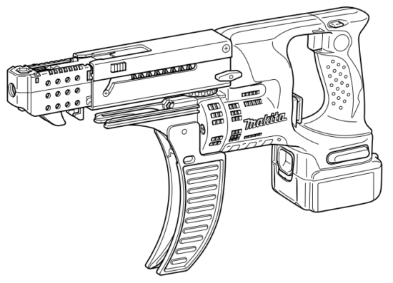


Original Instructions
| 1. Red indicator 2. Button 3. Battery cartridge 4. Indicator lamps 5. Check the button 6. Lever 7. Stopper base 8. Label on feeder box 9. Fenestella |
10. Casing 11. Adjusting the knob 12. Switch trigger 13. Reversing switch lever 14. Thumb screw 15. Plane bearing 16. Dust cover 17. Bit 18. Feeder box |
19. Screw strip 20. Screw guide 21. Driving position 22. Reverse button 23. Hook 24. Hanging hole 25. Wall |
SPECIFICATIONS
| Model | DFR540 | DFR550 | DFR750 |
| Screw strip | 4 x 25 – 55 mm | 4 x 45 – 75 mm | |
| No load speed (min -¹) | 4,000 | ||
| Overall length | 424 m | 464 mm | |
| Net weight | 2.0 – 3.0 kg | 2.1 – 3.1 kg | 2.1 – 3.2 kg |
| Rated voltage | D.C. 14.4 V | D.C. 18 V | D.C. 18 V |
- Due to our continuing program of research and development, the specifications herein are subject to change without notice.
- Specifications may differ from country to country.
- The weight may differ depending on the attachment(s), including the battery cartridge. The lightest and heaviest combinations, according to EPTA-Procedure 01/2014, are shown in the table.
Applicable battery cartridge and charger
| Battery cartridge | D.C.14.4 V Model | BL1415N/BL1430B/BL1440/BL1460B |
| D.C.18 V Model | BL1815N/BL1820B/BL1830B/BL1840B/BL1850B/BL1860B | |
| Charger | DC18RC/DC18RD/DC18RE/DC18SD/ DC18SE/DC18SF/DC18SH/DC18WC | |
- Some of the battery cartridges and chargers listed above may not be available depending on your region of residence.
- Only use the battery cartridges and chargers listed above. Use of any other battery cartridges and chargers may cause injury and/or fire.

ENE033-1
Intended use
The tool is intended for screw driving in wood, metal, and plastic.
General power tool safety warnings
GEA010-2
Save all warnings and instructions for future reference.
The term “power tool” in the warnings refers to your mains-operated (corded) power tool or battery-operated (cordless) power tool.
CORDLESS SCREWDRIVER SAFETY WARNINGS
GEB139-2
- Hold the power tool by insulated gripping surfaces, when performing an operation where the fastener may contact hidden wiring. Fasteners contacting a “live” wire may make exposed metal parts of the power tool “live” and could give the operator an electric shock.
- Always be sure you have a firm footing. Be sure no one is below when using the tool in high locations.
- Hold the tool firmly.
- Keep hands away from rotating parts.
- Do not touch the bit or the workpiece immediately after operation; they may be extremely hot and could burn your skin.
- Always secure the workpiece in a vise or similar hold-down device.
- Make sure there are no electrical cables, water pipes, gas pipes, etc. that could cause a hazard if damaged by the use of the tool.
SAVE THESE INSTRUCTIONS.
Important safety instructions for battery cartridge
ENC007-17
- Before using the battery cartridge, read all instructions and cautionary markings on (1) battery charger, (2) battery, and (3) product using the battery.
- Do not disassemble or tamper with the battery cartridge. It may result in a fire, excessive heat, or explosion.
- If the operating time has become excessively shorter, stop operating immediately. It may result in a risk of overheating, possible burns, and even an explosion.
- If electrolyte gets into your eyes, rinse them out with clear water and seek medical attention right away. It may result in loss of your eyesight.
- Do not short the battery cartridge:
(1) Do not touch the terminals with any conductive material.
(2) Avoid storing battery cartridges in a container with other metal objects such as nails, coins, etc.
(3) Do not expose the battery cartridge to water or rain.
A battery short can cause a large current flow, overheating, possible burns, and even a breakdown. - Do not store and use the tool and battery cartridge in locations where the temperature may reach or exceed 50 °C (122 °F).
- Do not incinerate the battery cartridge even if it is severely damaged or is completely worn out. The battery cartridge can explode in a fire.
- Do not nail, cut, crush, throw, drop the battery cartridge, or hit a hard object to the battery cartridge. Such conduct may result in a fire, excessive heat, or explosion.
- Do not use a damaged battery.
- The contained lithium-ion batteries are subject to the Dangerous Goods Legislation requirements.
For commercial transports e.g. by third parties or forwarding agents, the special requirements on packaging and labeling must be observed.
For the preparation of the item being shipped, consulting an expert for hazardous material is required. Please also observe possibly more detailed national regulations.
Tape or mask off open contacts and pack up the battery in such a manner that it cannot move around in the packaging. - When disposing of the battery cartridge, remove it from the tool and dispose of it in a safe place. Follow your local regulations relating to the disposal of batteries.
- Use the batteries only with the products specified by Makita. Installing the batteries to non-compliant products may result in a fire, excessive heat, explosion, or leak of electrolyte.
- If the tool is not used for a long period of time, the battery must be removed from the tool.
- During and after use, the battery cartridge may take on heat which can cause burns or low-temperature burns. Pay attention to the handling of hot battery cartridges.
- Do not touch the terminal of the tool immediately after use as it may get hot enough to cause burns.
- Do not allow chips, dust, or soil to stuck into the terminals, holes, and grooves of the battery cartridge. It may cause heating, catching fire, burst, and malfunction of the tool or battery cartridge, resulting in burns or personal injury.
- Unless the tool supports the use of near high-voltage electrical power lines, do not use the battery cartridge near high-voltage electrical power lines.
It may result in a malfunction or breakdown of the tool or battery cartridge. - Keep the battery away from children.
Tips for maintaining maximum battery life
- Charge the battery cartridge before completely discharged. Always stop tool operation and charge the battery cartridge when you notice less tool power.
- Never recharge a fully charged battery cartridge. Overcharging shortens the battery service life.
- Charge the battery cartridge at room temperature at 10 °C – 40 °C (50 °F – 104 °F). Let a hot battery cartridge cool down before charging it.
- When not using the battery cartridge, remove it from the tool or the charger.
- Charge the battery cartridge if you do not use it for a long period (more than six months).
FUNCTIONAL DESCRIPTION
CAUTION:
- Always be sure that the tool is switched off and the battery cartridge is removed before adjusting or checking the function of the tool.
Installing or removing the battery cartridge (Fig. 1)
- Always switch off the tool before installing or removing the battery cartridge.
- To remove the battery cartridge, slide it from the tool while sliding the button on the front of the cartridge.
- To install the battery cartridge, align the tongue on the battery cartridge with the groove in the housing and slip it into place. Always insert it all the way until it locks in place with a little click. If you can see the red indicator on the upper side of the button, it is not locked completely. Install it fully until the red indicator cannot be seen. If not, it may accidentally fall out of the tool, causing injury to you or someone around you.
- Do not use force when installing the battery cartridge. If the cartridge does not slide in easily, it is not being inserted correctly.
Tool/battery protection system
The tool is equipped with a tool/battery protection system. This system automatically cuts off the power to extend tool and battery life. The tool will automatically stop during
operation if the tool or battery is placed under one of the following conditions:
Overload protection
This protection works when the tool/battery is operated in a manner that causes it to draw an abnormally high current. In this situation, turn the tool off and stop the application that caused the tool to become overloaded.
Then turn the tool on to restart.
Overheat protection
This protection works when the tool or battery is overheated. In this situation, let the tool and battery cool before turning the tool on again.
Over-discharge protection
This protection works when the remaining battery capacity gets low. In this situation, remove the battery from the tool and charge the battery.
Indicating the remaining battery capacity
Only for battery cartridges with the indicator (Fig. 2)
Press the check button on the battery cartridge to indicate the remaining battery capacity. The indicator lamps light up for a few seconds.
Indicator lamps |
Remaining capacity | ||
| |
75% to 100% | ||
| |
50% to 75% | ||
| |
25% to 50% | ||
| |
0% to 25% | ||
| |
Charge the battery. | ||
| The battery may have malfunctioned. | |||


NOTE:
- Depending on the conditions of use and the ambient temperature, the indication may differ slightly from the actual capacity.
- The first (far left) indicator lamp will blink when the battery protection system works.
Setting for desired screw length (Fig. 3)
There are 7 positive-lock screw length settings. To obtain the desired setting, pull out the stopper base while depressing the lever until you see the number of the desired screw length (indicated on the label on the feeder box) appear to rest in the fenestella of the stopper base. See the table below for the relation between the number indicated on the label on the feeder box and the respective screw length.
For Models DFR540, DFR550
| The number indicated on the label | Screw length |
| 25 | 25 mm |
| 30 | 30 mm |
| 35 | 35 mm |
| 40 | 40 mm |
| 45 | 45 mm |
| 50 | 50 mm |
| 55 | 55 mm |
008238
For Model DFR750
| The number indicated on the label | Screw length |
| 45 | 45 mm |
| 50 | 50 mm |
| 55 | 55 mm |
| 60 | 60 mm |
| 65 | 65 mm |
| 70 | 70 mm |
| 75 | 75 mm |
008241
Adjusting the driving depth (Fig. 4)
Depress the stopper base as far as it will go. While keeping it in this position, turn the adjusting knob until the bit tip projects approx. 5 mm from the stopper base. Drive a trial screw. If the screw head projects above the surface of the workpiece, turn the adjusting knob in the “A” direction; if the screw head is counter-sunk, turn the adjusting the knob in the “B” direction.
Switch action (Fig. 5)
CAUTION:
- Before inserting the battery cartridge into the tool, always check to see that the switch trigger actuates properly and returns to the “OFF” position when released.
To start the tool, simply pull the switch trigger. Release the switch trigger to stop.
Reversing switch action (Fig. 6)
This tool has a reversing switch to change the direction of rotation. Depress the reversing switch lever from the A-side for clockwise rotation or from the B-side for counterclockwise rotation.
When the reversing switch lever is in the neutral position, the switch trigger cannot be pulled.
CAUTION:
- Always check the direction of rotation before operation.
- Use the reversing switch only after the tool comes to a complete stop. Changing the direction of rotation before the tool stops may damage the tool.
- When not operating the tool, always set the reversing switch lever to the neutral position.
ASSEMBLY
CAUTION:
- Always be sure that the tool is switched off and the battery cartridge is removed before carrying out any work on the tool.
Installing or removing the bit
Loosen the thumb screws which secure the casing. Pull out the casing in the direction of the arrow. (Fig. 7) Press the dust cover toward the plane bearing and pull out the bit. If the dust cover cannot be moved as far as the plane bearing, try it again after turning the bit slightly. To install the bit, insert it into the socket while turning it slightly. After installing, always make sure that the bit is securely held in place by trying to pull it out. (Fig. 8)
Installing screw strip
Insert the screw strip through the screw guide. Then insert it through the feeder box until the first screw reaches the position next to the driving position. (Fig. 9 & 10)
Removing screw strip
To remove the screw strip, just pull it out in the direction of the arrow. If you depress the reverse button, you can pull out the screw strip in the reverse direction of the arrow.
(Fig. 11 & 12)
Folding screw guide (Fig. 13)
The screw guide is foldable. Folding the screw guide allows space used for storage to be minimal.
Carry hook
The carrying hook is convenient for temporarily hooking the tool. It can be installed on either side of the tool. When removing the carrying hook, widen it by pressing its right ends ON BOTH SIDES in the direction of the arrow (1) and raise it in the direction of the arrow (2). (Fig. 14)
Using hole
- Never use the hanging hole for unintended purposes, for instance, tethering the tool at a high location. Bearing stress is a heavily loaded hole that may cause damage to the hole, resulting in injuries to you or people around or below you. (Fig. 15)
Use the hanging hole at the bottom rear of the tool to hang the tool on a wall using a hanging cord or similar strings.
OPERATION
Driving operation (Fig. 16)
Switch on the tool by pulling the switch trigger. Hold the tool squarely and firmly up against the driving surface. A screw will be automatically carried to the driving position and fastened.
CAUTION:
- Always check the bit carefully for wear before driving operations. Replace a worn bit or poor fastening may result.
- Always hold the tool squarely against the driving surface. Holding it at an angle may damage the screw heads and cause wear on the bit. This may also lead to poor fastening.
- Always keep the tool firmly against the driving surface until the driving is over. Failure to do so may cause insufficient fastening of screws.
- Be careful not to drive a screw onto another screw already fastened.
- Do not operate the tool without screws. It will damage the driving surface.
- Do not apply oil or grease on the sliding surface of the feeder box.
Driving in the corner (Fig. 17)
This tool can be used to drive at a position 15 mm away from the wall as shown in the figure.
CAUTION:
- Driving at a position closer than 15 mm to the wall or driving with the stopper base in contact with the wall may damage the screw heads and cause wear on the bit. This may also lead to the poor fastening of screws and malfunction of the tool.
MAINTENANCE
- Always be sure that the tool is switched off and the battery cartridge is removed before attempting to perform inspection or maintenance.
- Never use gasoline, benzene, thinner, alcohol, or the like. Discoloration, deformation, or cracks may result. To maintain product SAFETY and RELIABILITY, repairs, carbon brush inspection, and replacement, any other maintenance or adjustment should be performed by Makita Authorized or Factory Service Centers, always using Makita replacement parts.
OPTIONAL ACCESSORIES
These accessories or attachments are recommended for use with your Makita tool specified in this manual. The use of any other accessories or attachments might present a risk of injury to persons. Only use accessory or attachment for its stated purpose. If you need any assistance for more details regarding these accessories, ask your local Makita Service Center.
- Drywall screw strip
- Phillips bit
- Makita genuine battery and charger
- Plastic carrying case
NOTE:
- Some items in the list may be included in the tool package as standard accessories. They may differ from country to country.
Noise
ENG905-1
The typical A-weighted noise level is determined according to EN62841-2-2:
Model DFR540
Sound pressure level (LpA): 77 dB (A)
Uncertainty (K): 3 dB (A)
The noise level under working may exceed 80 dB (A).
Model DFR550
Sound pressure level (LpA): 78 dB (A)
Uncertainty (K): 3 dB (A)
The noise level under working may exceed 80 dB (A).
Model DFR750
Sound pressure level (LpA): 76 dB (A)
Uncertainty (K): 3 dB (A)
The noise level under working may exceed 80 dB (A).
ENG907-1
- The declared noise emission value(s) has been measured in accordance with a standard test method and may be used for comparing one tool with another.
- The declared noise emission value(s) may also be used in a preliminary assessment of exposure.
- Wear ear protection.
- The noise emission during actual use of the power tool can differ from the declared value(s) depending on the ways in which the tool is used especially what kind of workpiece is processed.
- Be sure to identify safety measures to protect the operator that is based on an estimation of exposure in the actual conditions of use (taking account of all parts of the operating cycle such as the times when the tool is switched off and when it is running idle in addition to the trigger time).
Vibration
ENG900-1
The vibration total value (tri-axial vector sum) determined according to EN62841-2-2: Work mode: screwdriving without impact
Vibration emission (ah): 2.5 m/s² or less
Uncertainty (K): 1.5 m/s²
ENG901-2
- The declared vibration total value(s) has been measured in accordance with a standard test method and may be used for comparing one tool with another.
- The declared vibration total value(s) may also be used in a preliminary assessment of exposure.
WARNING:
- The vibration emission during actual use of the power tool can differ from the declared value(s) depending on the ways in which the tool is used especially what kind of workpiece is processed.
- Be sure to identify safety measures to protect the operator that is based on an estimation of exposure in the actual conditions of use (taking account of all parts of the operating cycle such as the times when the tool is switched off and when it is running idle in addition to the trigger time).
EC Declaration of Conformity
For European countries only
The EC declaration of conformity is included as Annex A to this instruction manual.
Makita Europe N.V.
Jan-Baptist Vinkstraat 2,
3070 Kortenberg, Belgium
Makita Corporation
3-11-8, Sumiyoshi-Cho,
Anjo, Aichi 446-8502 Japan
www.makita.com
885286C992
ALA