Makita PC5000C Concrete Planer Instruction Manual

Instruction Manual
PC5001C


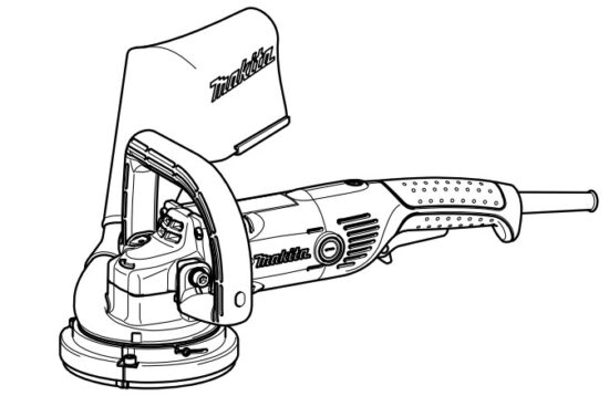
Explanation of general view
| 1. Lock lever | 14. Dust cover |
| 2. Switch trigger | 15. Screw |
| 3. Indication lamp | 16. Lock nut |
| 4. Base (for PC5001C only) | 17. Lock nut wrench |
| 5. Hex wrench | 18. Diamond wheel |
| 6. Front roller | 19. Shaft lock |
| 7. Hex socket head bolt | 20. Dust bag |
| 8. Stock removal amount | 21. Dust cover cap |
| 9. Base | 22. The whole roller holder |
| 10. Same level | 23. Hex bolt |
| 11. Square or ruler | 24. Limit mark |
| 12. Raise | 25. Brush holder cap |
| 13. Lower | 26. Screwdriver |
SPECIFICATIONS
| Model | PC5000C | PC5001C |
| Wheel diameter | 125 mm | |
| Hole diameter | 22.23 mm | |
| Spindle thread | M14 | |
| Rated speed (n) / No-load speed (no) | 10,000 min-1 | |
| Overall length | 437 mm | 479 mm |
| Net weight | 4.0 kg | 5.1 kg |
| Safety class | ||

- Due to our continuing program of research and development, the specifications herein are subject to change without notice.
- Specifications may differ from country to country.
- Weight according to EPTA-Procedure 01/2003
Intended use
The tool is intended for planning concrete surfaces.
Power supply
The tool should be connected only to a power supply of the same voltage as indicated on the nameplate, and can only be operated on a single-phase AC supply. They are double-insulated and can, therefore, also be used from sockets without earth wire.
General Power Tool Safety Warnings
WARNING Read all safety warnings and all instructions. Failure to follow the warnings and instructions may result in electric shock, fire, and/or serious injury.
Save all warnings and instructions for future reference.
CONCRETE PLANER SAFETY WARNINGS
Safety Warnings for Planing Operation:
- This power tool is intended to function as a planer with offset diamond wheels. Read all safety warnings, instructions, illustrations, and specifications provided with this power tool. Failure to follow all instructions listed below may result in electric shock, fire, and/or serious injury.
- Operations such as grinding with abrasive wheels, sanding, wire brushing, polishing or cutting-off are not recommended to be performed with this power tool. Operations for which the power tool was not designed may create a hazard and cause personal injury.
- Do not use accessories that are not specifically designed and recommended by the tool manufacturer. Just because the accessory can be attached to your power tool, it does not assure safe operation.
- The rated speed of the accessory must be at least equal to the maximum speed marked on the power tool. Accessories running faster than their rated speed can break and fly apart.
- The outside diameter and the thickness of your accessory must be within the capacity rating of your power tool. Incorrectly sized accessories cannot be adequately guarded or controlled.
- Threaded mounting of accessories must match the tool spindle thread. For accessories mounted by flanges, the arbor hole of the accessory must fit the locating diameter of the flange. Accessories that do not match the mounting hardware of the power tool will run out of balance, vibrate excessively, and may cause loss of control.
- Do not use a damaged accessory. Before each use inspects the accessory such as offset diamond wheels for chips and cracks. If a power tool or accessory is dropped, inspect for damage or install an undamaged accessory. After inspecting and installing an accessory, position yourself and bystanders away from the plane of the rotating accessory and run the power tool at maximum no-load speed for one minute. Damaged accessories will normally break apart during this test time.
- Wear personal protective equipment. Depending on the application, use a face shield, safety goggles, or safety glasses. As appropriate, wear a dust mask, hearing protectors, gloves, and a workshop apron capable of stopping small abrasive or workpiece fragments. The eye protection must be capable of stopping flying debris generated by various operations. The dust mask or respirator must be capable of filtrating particles generated by your operation. Prolonged exposure to high-intensity noise may cause hearing loss.
- Keep bystanders a safe distance away from the work area. Anyone entering the work area must wear personal protective equipment. Fragments of a workpiece or of a broken accessory may fly away and cause injury beyond the immediate area of operation.
- Hold the power tool by insulated gripping surfaces only, when performing an operation where the cutting accessory may contact hidden wiring or its own cord. Cutting accessory contacting a “live” wire may make exposed metal parts of the power tool “live” and could give the operator an electric shock.
- Position the cord clear of the spinning accessory.
If you lose control, the cord may be cut or snagged and your hand or arm may be pulled into the spinning accessory. - Never lay the power tool down until the accessory has come to a complete stop. The spinning accessory may grab the surface and pull the power tool out of your control.
- Do not run the power tool while carrying it at your side. Accidental contact with the spinning accessory could snag your clothing, pulling the accessory into your body.
- Regularly clean the power tool’s air vents. The motor’s fan will draw the dust inside the housing and excessive accumulation of powdered metal may cause electrical hazards.
- Do not operate the power tool near flammable materials. Sparks could ignite these materials.
- Do not use accessories that require liquid coolants. Using water or other liquid coolants may result in electrocution or shock.
Kickback and Related Warnings
Kickback is a sudden reaction to a pinched or snagged rotating wheel, backing pad, brush, or any other accessory. Pinching or snagging causes rapid stalling of the rotating accessory which in turn causes the uncontrolled power tool to be forced in the direction opposite of the accessory’s rotation at the point of the binding.
For example, if an abrasive wheel is snagged or pinched by the workpiece, the edge of the wheel that is entering into the pinch point can dig into the surface of the material causing the wheel to climb out or kick out. The wheel may either jump toward or away from the operator, depending on the direction of the wheel’s movement at the point of pinching. Abrasive wheels may also break under these conditions.
Kickback is the result of power tool misuse and/or incorrect operating procedures or conditions and can be avoided by taking proper precautions as given below.
a) Maintain a firm grip on the power tool and position your body and arm to allow you to resist kickback forces. Always use an auxiliary handle, if provided, for maximum control over kickback or torque reaction during start-up. The operator can control torque reactions or kickback forces if proper precautions are taken.
b) Never place your hand near the rotating accessory. The accessory may kick back over your hand.
c) Do not position your body in the area where the power tool will move if kickback occurs. Kickback will propel the tool in a direction opposite to the wheel’s movement at the point of snagging.
d) Use special care when working corners, sharp edges, etc. Avoid bouncing and snagging the accessory. Corners, sharp edges, or bouncing have a tendency to snag the rotating accessory and cause loss of control or kickback.
e) Do not attach a saw chain woodcarving blade or toothed saw blade. Such blades create frequent kickback and loss of control.
Safety Warnings Specific for Planing Operation:
a) Use only wheel types that are recommended for your power tool and the specific guard designed for the selected wheel. Wheels for which the power tool was not designed cannot be adequately guarded and are unsafe.
b) Always use undamaged wheel flanges that are of the correct size and shape for your selected wheel. Proper wheel flanges support the wheel thus reducing the possibility of wheel breakage.
Additional Safety Warnings: - Always install the dust cover before operation.
- Be careful not to damage the spindle, the flange (especially the installing surface) or the lock nut. Damage to these parts could result in wheel breakage.
- Make sure the wheel is not contacting the workpiece before the switch is turned on.
- Before using the tool on an actual workpiece, let it run for a while. Watch for vibration or wobbling that could indicate poor installation or a poorly balanced wheel.
- Do not leave the tool running. Operate the tool only when hand-held.
- Do not touch the offset diamond wheel immediately after operation; it may be extremely hot and could burn your skin.
- Observe the instructions of the manufacturer for correct mounting and use of wheels. Handle and store wheels with care.
- Do not use separate reducing bushings or adaptors to adapt large hole wheels.
- Use only flanges specified for this tool.
- Pay attention that the wheel continues to rotate after the tool is switched off.
- If a working place is extremely hot and humid, or badly polluted by conductive dust, use a short-circuit breaker (30 mA) to assure operator safety.
- Do not use the tool on any materials containing asbestos.
SAVE THESE INSTRUCTIONS.
DO NOT let comfort or familiarity with the product (gained from repeated use) replace strict adherence to safety rules for the subject product. MISUSE or failure to follow the safety rules stated in this instruction manual may cause serious personal injury.

FUNCTIONAL DESCRIPTION
CAUTION:
- Always be sure that the tool is switched off and unplugged before adjusting or checking the function on the tool.
Switch action (Fig. 1)
CAUTION:
- Before plugging in the tool, always check to see that the switch trigger actuates properly and returns to the “OFF” position when released.
For tool with the lock-on switch
To start the tool, simply pull the switch trigger (A). Release the switch trigger to stop. For continuous operation, pull the switch trigger (A) and then push in the lock lever (B).
To stop the tool from the locked position, pull the switch trigger (A) fully, then release it.
For tool with the lock-off switch
To prevent the switch trigger from being accidentally pulled, a lock lever is provided. To start the tool, push in the lock lever (B) and then pull the switch trigger (A). Release the switch trigger to stop.
For tool with the lock on and lock-off switch
To prevent the switch trigger from being accidentally pulled, a lock lever is provided. To start the tool, push in the lock lever (B) and then pull the switch trigger (A). Release the switch trigger to stop. For continuous operation, push in the lock lever (B), pull the switch trigger (A), and then push in the lock lever (B) further. To stop the tool from the locked position, pull the switch trigger (A) fully, then release it.
Electronic function
Constant speed control
- Possible to get fine finish, because the rotating speed is kept constantly even under the loaded condition.
- Additionally, when the load on the tool exceeds admissible levels, power to the motor is reduced to protect the motor from overheating. When the load returns to admissible levels, the tool will operate as normal.
Soft start feature
- Soft start because of suppressed starting shock.
Indication lamp (Fig. 2)
The indication lamp lights up green when the tool is plugged. If the indicator lamp does not light up, the main cord or the controller may be defective. The indication lamp is lit but the tool does not start even if the tool is switched on, the carbon brushes may be worn out, or the controller, the motor, or the ON/OFF switch may be defective.
Unintentional restart proof
Even lock lever keeping the switch trigger depressed (Lock-on position) does not allow the tool to restart even when the tool is plugged.
At this time, the indication lamp flickers red and shows the unintentional restart proof device is on function.
To cancel the unintentional restart proof, pull the switch trigger fully, then release it.
Level planing (for PC5001C only) (Fig. 3)
To level, a surface, the base of the planer should be aligned with the diamond wheel. The front roller should be adjusted (use hex wrench) upward to the level required for the desired stock removal amount.
To change the amount of stock (concrete) removed, loosen the hex socket head bolts on the base holder with the hex wrench. Raise or lower the front roller to adjust the gap between it and the diamond wheel. The difference is the stock removal amount. Then secure the hex socket head bolts very carefully. (Fig. 4)
NOTE:
- Maximum stock removal should be less than 4.0 mm.
Tilting base for smoother planning (for PC5001C only) (Fig. 5)
For smooth removal of given surface roughness or texture, tilting the base is helpful. Use the hex wrench to loosen the two hex socket head bolts securing the base on either side.
Use a hex wrench to lower the three hex socket head bolts on the base by turning them on the base clockwise. (Fig. 6)
Use a square or ruler to obtain the desired base angle in relation to the diamond wheel. Then secure carefully the hex socket head bolts on either side of the base. Adjust center of the base near the wheel so that it is on the same level as the wheel. (Fig. 7)
NOTE:
- After base adjustment, turn the three hex socket head bolts on the base counterclockwise until the heads are flush with the back side of the base. Turn gently or base adjustment will be thrown off.
Base adjustment to compensate for wheel wear (for PC5001C only)
With long use, the diamond wheel will wear and thus create a gap with the planing surface so that performance becomes poor. Check the tool after every 4 or 5 hours of use.
If the wheel and base surfaces are not aligned, loosen two hex socket head bolts securing the base. Turn three hex socket head bolts on the base clockwise and adjust the base so as to be level with the wheel surface. Retighten firmly the hex socket head bolts securing the base and then lightly turn the hex socket head bolts counterclockwise so that the hex socket head bolts do not come loose during operation.
Dust cover adjustment (Fig. 8)
Loosen the screw. and adjust the dust cover’s brush level.
The dust cover’s brush should be either flush with the diamond wheel surface or very slightly above (when the tool is inverted) 0.5 mm. Suction/pickup will be poor if they are not approximately on the same level. After adjusting, be sure to tighten the screw firmly.
To adjust the dust cover, grip it on the outside; turn clockwise to raise, counterclockwise to lower.
ASSEMBLY
CAUTION:
- Always be sure that the tool is switched off and unplugged before carrying out any work on the tool.
Installing or removing the diamond wheel (Fig. 9)
To replace a worn diamond wheel with a new one, press in the shaft lock to hold the shaft steady, then loosen the lock nut counterclockwise with the lock nut wrench provided.
Remove the worn diamond wheel.
To install a new one, follow the above removal procedure in reverse.
When installing a diamond wheel, always make sure to tighten the lock nut firmly.
NOTE:
- The ordinary diamond wheels on the market have no exhaust holes, so dust evacuation is poor. Also, if the installing hole is not of the exact diameter, tool vibration occurs and accidents can occur. ALWAYS USE A MAKITA OFFSET DIAMOND WHEEL.
Replacing the dust cover’s brush
To remove the dust cover’s brush from the dust cover, grab an end of the dust cover’s brush and take it out slowly. (Fig. 10)
To install the dust cover’s brush, firstly align both ends of the brush with the groove of the dust cover. (Fig. 11)
And then insert the brush all the way into the groove of the dust cover by using a slotted driver or another appropriate tool.
Dust bag (Fig. 12)
To install a dust bag, slip it onto the dust port. Always make sure to slip onto the dust port all the way until it stops so that it does not come off during operation.
Remove the dust bag when it begins to touch the cutting surface.
This is a sign that it is full. Failure to the empty bag will lead to poor suction/pickup.
Connecting a vacuum cleaner (Fig. 13)
When you wish to perform a clean planning operation, connect a Makita vacuum cleaner to your tool as shown in the figure.
OPERATION (Fig. 14)
Always use the top grip (auxiliary handle) and firmly hold the tool by the top grip and switch handle during operations.
Planing in corners
For PC5000C
Flush planing of corners is possible after first removing the dust cover cap.
For PC5001C only (Fig. 15)
Before performing the flush planing of corners, remove the hex bolt which secures the roller holder and base holder, and then takes away the whole roller holder.
Next, loosen the hex socket head bolt and take away the dust cover cap and then adjust the dust cover in a proper position according to your work. (Fig. 16)
MAINTENANCE
CAUTION:
- Always be sure that the tool is switched off and unplugged before attempting to perform inspection or maintenance.
- Never use gasoline, benzene, thinner, alcohol, or the like. Discoloration, deformation, or cracks may result.
Replacing carbon brushes (Fig. 17)
Remove and check the carbon brushes regularly. Replace when they wear down to the limit mark. Keep the carbon brushes clean and free to slip in the holders. Both carbon brushes should be replaced at the same time. Use only identical carbon brushes.
Use a screwdriver to remove the brush holder caps. Take out the worn carbon brushes, insert the new ones, and secure the brush holder caps. (Fig. 18)
To maintain product SAFETY and RELIABILITY, repairs, and any other maintenance or adjustment should be performed by Makita Authorized Service Centers, always using Makita replacement parts.
OPTIONAL ACCESSORIES

- These accessories or attachments are recommended for use with your Makita tool specified in this manual. The use of any other accessories or attachments might present a risk of injury to persons. Only use accessory or attachment for its stated purpose.
If you need any assistance with more details regarding these accessories, ask your local Makita Service Center. - Offset diamond wheel (Dry type)
Dust cover brush
NOTE:
- Some items in the list may be included in the tool package as standard accessories. They may differ from country to country.
Noise
The typical A-weighted noise level is determined according to EN60745:
Model PC5000C
Sound pressure level (LpA): 91 dB (A)
Sound power level (LWA): 102 dB (A)
Uncertainty (K): 3 dB (A)
Model PC5001C
Sound pressure level (LpA): 89 dB (A)
Sound power level (LWA): 100 dB (A)
Uncertainty (K): 3 dB (A)
Wear ear protection.
Vibration
The vibration total value (tri-axial vector sum) determined according to EN60745:
Model PC5000C
Work mode: planing concrete
Vibration emission (ah): 12.0 m/s2
Uncertainty (K): 1.5 m/s2
Model PC5001C
Work mode: planing concrete
Vibration emission (ah): 12.5 m/s2
Uncertainty (K): 2.5 m/s2
- The declared vibration emission value has been measured in accordance with the standard test method and may be used for comparing one tool with another.
- The declared vibration emission value may also be used in a preliminary assessment of exposure.
- The declared vibration emission value is used for the main applications of the power tool. However, if the power tool is used for other applications, the vibration emission value may be different.
- The vibration emission during actual use of the power tool can differ from the declared emission value depending on the ways in which the tool is used.
- Be sure to identify safety measures to protect the operator that are based on an estimation of exposure in the actual conditions of use (taking account of all parts of the operating cycle such as the times when the tool is switched off and when it is running idle in addition to the trigger time).
EC Declaration of Conformity
For European countries only
The EC declaration of conformity is included as Annex A to this instruction manual.
Makita Europe N.V.
Jan-Baptist Vinkstraat 2,
3070 Kortenberg, Belgium
Makita Corporation
3-11-8, Sumiyoshi-cho,
Anjo, Aichi 446-8502 Japan
www.makita.com