Makita DLS714 Cordless Slide Compound Miter Saw Instruction Manual

INSTRUCTION MANUAL
DLS714


Original instructions
SPECIFICATIONS
| Model: | DLS714 |
| Blade diameter | 190 mm |
| Hole (arbor) diameter (country-specific) | 20 mm or 15.88 mm |
| Max. kerf thickness of the saw blade | 2.2 mm |
| Max. miter angle | Left 47°, Right 57° |
| Max. bevel angle | Left 45°, Right 5° |
| No-load speed | 5,700 min-1 |
| Dimensions (L x W x H) | 655 mm x 430 mm x 445 mm |
| Rated voltage | D.C. 36 V |
| Net weight | 14.4 – 14.7 kg |
- Due to our continuing program of research and development, the specifications herein are subject to change without notice.
- Specifications may differ from country to country.
- The weight may differ depending on the attachment(s), including the battery cartridge. The lightest and heaviest combinations, according to EPTA-Procedure 01/2014, are shown in the table.
Applicable battery cartridge and charger
| Battery cartridge | BL1815N / BL1820B / BL1830B / BL1840B / BL1850B / BL1860B |
| Charger | DC18RC / DC18RD / DC18RE / DC18SD / DC18SE / DC18SF /DC18SH |
- Some of the battery cartridges and chargers listed above may not be available depending on your region of residence.
WARNING: Only use the battery cartridges and chargers listed above. Use of any other battery cartridges and chargers may cause injury and/or fire.
Cutting capacities (H x W) with blade 190 mm in diameter
| Miter angle | Bevel angle | ||
| 45° (left) | 0° | 5° (right) | |
| 0° | 40 mm x 300 mm | 52 mm x 300 mm | 40 mm x 300 mm |
| 45 mm x 265 mm (NOTE 1) | 60 mm x 265 mm (NOTE 1) | ||
| 45° (left and right) | 40 mm x 212 mm | 52 mm x 212 mm | |
| 45 mm x 185 mm (NOTE 2) | 60 mm x 185 mm (NOTE 2) | ||
| 57° (right) | 52 mm x 163 mm | ||
| 60 mm x 145 mm (NOTE 3) | |||
- Max. Cutting capacity when using a wood facing 20 mm thickness
- Max. Cutting capacity when using a wood facing 15 mm thickness
- Max. Cutting capacity when using a wood facing 10 mm thickness
Symbols
The followings show the symbols which may be used for the equipment. Be sure that you understand their meaning before use.
| Read the instruction manual. | |
| To avoid injury from flying debris, keep holding the saw head down, after making cuts, until the blade has come to a complete stop. | |
| When performing slide cut, first pull carriage fully and press down handle, then push carriage toward the guide fence. | |
| Do not place hands or fingers close to the blade. | |
| Always set SUB-FENCE to the left position when performing left bevel cuts. Failure to do so may cause serious injury to the operator. |


Intended use
The tool is intended for accurate straight and miter cutting in wood. With appropriate saw blades, aluminum can also be sawed.
Do not use the saw to cut other than wood, aluminum, or similar materials.
SAFETY WARNINGS
General power tool safety warnings
WARNING: Read all safety warnings, instructions, illustrations, and specifications provided with this power tool. Failure to follow all instructions listed below may result in electric shock, fire, and/or serious injury.
Save all warnings and instructions for future reference.
The term “power tool” in the warnings refers to your mains-operated (corded) power tool or battery-operated (cordless) power tool.
Work area safety
- Keep the work area clean and well-lit. Cluttered or dark areas invite accidents.
- Do not operate power tools in explosive atmo- spheres, such as in the presence of flammable liquids, gases, or dust. Power tools create sparks that may ignite dust or fumes.
- Keep children and bystanders away while operating a power tool. Distractions can cause you to lose control.
Electrical safety
- Power tool plugs must match the outlet. Never modify the plug in any way. Do not use any adapter plugs with earthed (grounded) power tools. Unmodified plugs and matching outlets will reduce the risk of electric shock.
- Avoid body contact with earthed or grounded surfaces, such as pipes, radiators, ranges, and refrigerators. There is an increased risk of electric shock if your body is earthed or grounded.
- Do not expose power tools to rain or wet conditions. Water entering a power tool will increase the risk of electric shock.
- Do not abuse the cord. Never use the cord for carrying, pulling, or unplugging the power tool. Keep cord away from heat, oil, sharp edges, or moving parts. Damaged or entangled cords increase the risk of electric shock.
- When operating a power tool outdoors, use an extension cord suitable for outdoor use. The use of a cord suitable for outdoor use reduces the risk of electric shock.
- If operating a power tool in a damp location is unavoidable, use a residual current device (RCD) protected supply. The use of an RCD reduces the risk of electric shock.
- Power tools can produce electromagnetic fields (EMF) that are not harmful to the user. However, users of pacemakers and other similar medical devices should contact the maker of their device and/or doctor for advice before operating this power tool.
Personal safety
- Stay alert, watch what you are doing, and use common sense when operating a power tool.
Do not use a power tool while you are tired or under the influence of drugs, alcohol, or medication. A moment of inattention while operating power tools may result in serious personal injury. - Use personal protective equipment. Always wear eye protection. Protective equipment such as a dust mask, non-skid safety shoes, hard hat, or hearing protection used for appropriate conditions will reduce personal injuries.
- Prevent unintentional starting. Ensure the switch is in the off-position before connecting to a power source and/or battery pack, picking up or carrying the tool. Carrying power tools with your finger on the switch or energizing power tools that have the switch on invites accidents.
- Remove any adjusting key or wrench before turning the power tool on. A wrench or a key left attached to a rotating part of the power tool may result in personal injury.
- Do not overreach. Keep proper footing and balance at all times. This enables better control of the power tool in unexpected situations.
- Dress properly. Do not wear loose clothing or jewelry. Keep your hair and clothing away from moving parts. Loose clothes, jewelry, or long hair can be caught in moving parts.
- If devices are provided for the connection of dust extraction and collection facilities, ensure these are connected and properly used. The use of dust collection can reduce dust-related hazards.
- Do not let familiarity gained from frequent use of tools allow you to become complacent and ignore tool safety principles. A careless action can cause severe injury within a fraction of a second.
- Always wear protective goggles to protect your eyes from injury when using power tools. The goggles must comply with ANSI Z87.1 in the USA, EN 166 in Europe, or AS/NZS 1336 in Australia/New Zealand. In Australia/New Zealand, it is legally required to wear a face shield to protect your face, too.

It is an employer’s responsibility to enforce the use of appropriate safety protective equipment by the tool operators and by other persons in the immediate working area.
Power tool use and care
- Do not force the power tool. Use the correct power tool for your application. The correct power tool will do the job better and safer at the rate at which it was designed.
- Do not use the power tool if the switch does not turn on and off. Any power tool that cannot be controlled with the switch is dangerous and must be repaired.
- Disconnect the plug from the power source and/or remove the battery pack, if detachable, from the power tool before making any adjustments, changing accessories, or storing power tools. Such preventive safety measures reduce the risk of starting the power tool accidentally.
- Store idle power tools out of the reach of children and do not allow persons unfamiliar with the power tool or these instructions to operate the power tool. Power tools are dangerous in the hands of untrained users.
- Maintain power tools and accessories. Check for misalignment or binding of moving parts, breakage of parts, and any other condition that may affect the power tool’s operation. If damaged, have the power tool repaired before use. Many accidents are caused by poorly maintained power tools.
- Keep cutting tools sharp and clean. Properly maintained cutting tools with sharp cutting edges are less likely to bind and are easier to control.
- Use the power tool, accessories and tool bits, etc. in accordance with these instructions, taking into account the working conditions and the work to be performed. Use of the power tool for operations different from those intended could result in a hazardous situation.
- Keep handles and grasping surfaces dry, clean, and free from oil and grease. Slippery handles and grasping surfaces do not allow for safe handling and control of the tool in unexpected situations.
- When using the tool, do not wear cloth work gloves which may be entangled. The entanglement of cloth work gloves in the moving parts may result in personal injury.
Battery tool use and care
- Recharge only with the charger specified by the manufacturer. A charger that is suitable for one type of battery pack may create a risk of fire when used with another battery pack.
- Use power tools only with specifically designated battery packs. The use of any other battery packs may create a risk of injury and fire.
- When the battery pack is not in use, keep it away from other metal objects, like paper clips, coins, keys, nails, screws, or other small metal objects, that can make a connection from one terminal to another. Shorting the battery terminals together may cause burns or a fire.
- Under abusive conditions, liquid may be ejected from the battery; avoid contact. If contact accidentally occurs, flush with water. If liquid contacts the eyes, additionally seek medical help. Liquid ejected from the battery may cause irritation or burns.
- Do not use a battery pack or tool that is damaged or modified. Damaged or modified batteries may exhibit unpredictable behavior resulting in fire, explosion, or risk of injury.
- Do not expose a battery pack or tool to fire or excessive temperature. Exposure to fire or temperature above 130 °C may cause an explosion.
- Follow all charging instructions and do not charge the battery pack or tool outside the temperature range specified in the instructions. Charging improperly or at temperatures outside the specified range may damage the battery and increase the risk of fire.
Service
- Have your power tool serviced by a qualified repair person using only identical replacement parts. This will ensure that the safety of the power tool is maintained.
- Never service damaged battery packs. Service of battery packs should only be performed by the manufacturer or authorized service providers.
- Follow instructions for lubricating and changing accessories.
Safety instructions for miter saws
- Mitre saws are intended to cut wood or woodlike products, they cannot be used with abrasive cut-off wheels for cutting ferrous material such as bars, rods, studs, etc. Abrasive dust causes moving parts such as the lower guard to jam. Sparks from abrasive cutting will burn the lower guard, the kerf insert, and other plastic parts.
- Use clamps to support the workpiece whenever possible. If supporting the workpiece by hand, you must always keep your hand at least 100 mm from either side of the saw blade. Do not use this saw to cut pieces that are too small to be securely clamped or held by hand. If your hand is placed too close to the saw blade, there is an increased risk of injury from blade contact.
- The workpiece must be stationary and clamped or held against both the fence and the table. Do not feed the workpiece into the blade or cut “freehand” in any way. Unrestrained or moving workpieces could be thrown at high speeds, causing injury.
- Push the saw through the workpiece. Do not pull the saw through the workpiece. To make a cut, raise the saw head and pull it out over the workpiece without cutting, start the motor, press the saw head down and push the saw through the workpiece. Cutting on the pull stroke is likely to cause the saw blade to climb on top of the workpiece and violently throw the blade assembly towards the operator.
- Never cross your hand over the intended line of cutting either in front or behind the saw blade. Supporting the workpiece “cross-handed” i.e. holding the workpiece to the right of the saw blade with your left hand or vice versa is very dangerous.
► Fig.1 - Do not reach behind the fence with either hand closer than 100 mm from either side of the saw blade, to remove wood scraps, or for any other reason while the blade is spinning. The proximity of the spinning saw blade to your hand may not be obvious and you may be seriously injured.
- Inspect your workpiece before cutting. If the workpiece is bowed or warped, clamp it with the outside bowed face toward the fence. Always make certain that there is no gap between the workpiece, fence, and table along the line of the cut. Bent or warped workpieces can twist or shift and may cause binding on the spinning saw blade while cutting. There should be no nails or foreign objects in the workpiece.
- Do not use the saw until the table is clear of all tools, wood scraps, etc., except for the workpiece. Small debris or loose pieces of wood or other objects that contact the revolving blade can be thrown at high speed.
- Cut only one workpiece at a time. Stacked multiple workpieces cannot be adequately clamped or braced and may bind on the blade or shift during cutting.
- Ensure the miter saw is mounted or placed on a level, firm work surface before use. A level and firm work surface reduce the risk of the miter saw becoming unstable.
- Plan your work. Every time you change the bevel or miter angle setting, make sure the adjustable fence is set correctly to support the workpiece and will not interfere with the blade or the guarding system. Without turning the tool “ON” and with no workpiece on the table, move the saw blade through a complete simulated cut to assure there will be no interference or danger of cutting the fence.
- Provide adequate support such as table extensions, saw horses, etc. for a workpiece that is wider or longer than the tabletop. Workpieces longer or wider than the miter saw table can tip if not securely supported. If the cut-off piece or workpiece tips, it can lift the lower guard or be thrown by the spinning blade.
- Do not use another person as a substitute for a table extension or as additional support. Unstable support for the workpiece can cause the blade to bind or the workpiece to shift during the cutting operation pulling you and the helper into the spinning blade.
- The cut-off piece must not be jammed or pressed by any means against the spinning saw blade. If confined, i.e. using length stops, the cut-off piece could get wedged against the blade and thrown violently.
- Always use a clamp or a fixture designed to properly support round material such as rods or tubing. Rods have a tendency to roll while being cut, causing the blade to “bite” and pull the work with your hand into the blade.
- Let the blade reach full speed before contacting the workpiece. This will reduce the risk of the workpiece being thrown.
- If the workpiece or blade becomes jammed, turn the miter saw off. Wait for all moving parts to stop and disconnect the plug from the power source and/or remove the battery pack. Then work to free the jammed material. Continued sawing with a jammed workpiece could cause loss of control or damage to the miter saw.
- After finishing the cut, release the switch, hold the saw head down and wait for the blade to stop before removing the cut-off piece. Reaching with your hand near the coasting blade is dangerous.
- Hold the handle firmly when making an incomplete cut or when releasing the switch before the saw head is completely in the down position. The braking action of the saw may cause the saw head to be suddenly pulled downward, causing a risk of injury.
- Only use the saw blade with the diameter that is marked on the tool or specified in the manual. The use of an incorrectly sized blade may affect the proper guarding of the blade or guard operation which could result in serious personal injury.
- Only use the saw blades that are marked with a speed equal to or higher than the speed marked on the tool.
- Do not use the saw to cut other than wood, aluminum, or similar materials.
- (For European countries only) Always use the blade which conforms to EN847-1.
Additional instructions
- Make workshop kid proof with padlocks.
- Never stand on the tool. Serious injury could occur if the tool is tipped or if the cutting tool is unintentionally contacted.
- Never leave the tool running unattended. Turn the power off. Do not leave the tool until it comes to a complete stop.
- Do not operate the saw without guards in place. Check blade guard for proper closing before each use. Do not operate the saw if the blade guard does not move freely and close instantly. Never clamp or tie the blade guard into the open position.
- Keep hands out of the path of the saw blade. Avoid contact with any coasting blade. It can still cause severe injury.
- To reduce the risk of injury, return the carriage to the full rear position after each crosscut operation.
- Always secure all moving portions before carrying the tool.
- The stopper pin which locks the cutter head down is for carrying and storage purposes only and not for any cutting operations.
- Check the blade carefully for cracks or damage before operation. Replace cracked or damaged blade immediately. Gum and wood pitch hardened on blades slows the saw and increases the potential for kickback. Keep the blade clean by first removing it from the tool, then cleaning it with gum and pitch remover, hot water, or kerosene. Never use gasoline to clean the blade.
- While making a slide cut, KICKBACK can occur. KICKBACK occurs when the blade binds in the workpiece during a cutting operation and the saw blade is driven rapidly towards the operator. Loss of control and serious personal injury can result. If the blade begins to bind during a cutting operation, do not continue to cut and release the switch immediately.
- Use only flanges specified for this tool.
- Be careful not to damage the arbor, flanges (especially the installing surface), or bolt. Damage to these parts could result in blade breakage.
- Make sure that the turn base is properly secured so it will not move during operation. Use the holes in the base to fasten the saw to a stable work platform or bench. NEVER use a tool where operator positioning would be awkward.
- Make sure the shaft lock is released before the switch is turned on.
- Be sure that the blade does not contact the turn base in the lowest position.
- Hold the handle firmly. Be aware that the saw moves up or down slightly during start-up and stopping.
- Make sure the blade is not contacting the workpiece before the switch is turned on.
- Before using the tool on an actual workpiece, let it run for a while. Watch for vibration or wobbling that could indicate poor installation or a poorly balanced blade.
- Stop operation immediately if you notice anything abnormal.
- Do not attempt to lock the trigger in the “ON” position.
- Always use accessories recommended in this manual. The use of improper accessories such as abrasive wheels may cause an injury.
- Some material contains chemicals that may be toxic. Take caution to prevent dust inhalation and skin contact. Follow material supplier safety data.
Additional safety rules for the laser
- LASER RADIATION, DO NOT STARE INTO THE BEAM OR VIEW DIRECTLY WITH OPTICAL INSTRUMENTS, CLASS 2M LASER PRODUCT.
SAVE THESE INSTRUCTIONS.

Important safety instructions for battery cartridge
- Before using the battery cartridge, read all instructions and cautionary markings on (1) battery charger, (2) battery, and (3) product using the battery.
- Do not disassemble or tamper with the battery cartridge. It may result in a fire, excessive heat, or explosion.
- If the operating time has become excessively shorter, stop operating immediately. It may result in a risk of overheating, possible burns, and even an explosion.
- If electrolyte gets into your eyes, rinse them out with clear water and seek medical attention right away. It may result in loss of your eyesight.
- Do not short the battery cartridge:
(1) Do not touch the terminals with any conductive material.
(2) Avoid storing the battery cartridge in a container with other metal objects such as nails, coins, etc.
(3) Do not expose the battery cartridge to water or rain. A battery short can cause a large current flow, overheating, possible burns, and even a breakdown. - Do not store and use the tool and battery cartridge in locations where the temperature may reach or exceed 50 °C (122 °F).
- Do not incinerate the battery cartridge even if it is severely damaged or is completely worn out. The battery cartridge can explode in a fire.
- Do not nail, cut, crush, throw, drop the battery cartridge, or hit a hard object to the battery cartridge. Such conduct may result in a fire, excessive heat, or explosion.
- Do not use a damaged battery.
- The contained lithium-ion batteries are subject to the Dangerous Goods Legislation requirements. For commercial transports e.g. by third parties or forwarding agents, the special requirements on packaging and labeling must be observed. For the preparation of the item being shipped, consulting an expert for hazardous material is required. Please also observe possibly more detailed national regulations. Tape or mask off open contacts and pack up the battery in such a manner that it cannot move around in the packaging.
- When disposing of the battery cartridge, remove it from the tool and dispose of it in a safe place. Follow your local regulations relating to the disposal of batteries.
- Use the batteries only with the products specified by Makita. Installing the batteries to non-compliant products may result in a fire, excessive heat, explosion, or leak of electrolyte.
- If the tool is not used for a long period of time, the battery must be removed from the tool.
- During and after use, the battery cartridge may take on heat which can cause burns or low-temperature burns. Pay attention to the handling of hot battery cartridges.
- Do not touch the terminal of the tool immediately after use as it may get hot enough to cause burns.
- Do not allow chips, dust, or soil to stuck into the terminals, holes, and grooves of the battery cartridge. It may cause heating, catching fire, burst, and malfunction of the tool or battery cartridge, resulting in burns or personal injury.
- Unless the tool supports the use of near high-voltage electrical power lines, do not use the battery cartridge near high-voltage electrical power lines. It may result in a malfunction or breakdown of the tool or battery cartridge.
- Keep the battery away from children.
SAVE THESE INSTRUCTIONS.
Use of non-genuine Makita batteries, or batteries that have been altered, may result in the battery bursting causing fires, personal injury, and damage. It will also void the Makita warranty for the Makita tool and charger.

Tips for maintaining maximum battery life
- Charge the battery cartridge before completely discharged. Always stop tool operation and charge the battery cartridge when you notice less tool power.
- Never recharge a fully charged battery cartridge. Overcharging shortens the battery service life.
- Charge the battery cartridge at room temperature at 10 °C – 40 °C (50 °F – 104 °F). Let a hot battery cartridge cool down before charging it.
- When not using the battery cartridge, remove it from the tool or the charger. 5. Charge the battery cartridge if you do not use it for a long period (more than six months).
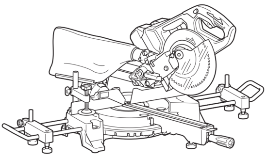
PARTS DESCRIPTION
► Fig.2
| 1 | Lock-off button | 2 | Switch trigger | 3 | Blade case | 4 | Adjusting screw (for lower limit position) |
| 5 | Adjusting bolt (for maximum cutting capacity) | 6 | Stopper arm | 7 | Dust bag | 8 | Bevel scale |
| 9 | Blade guard | 10 | Vertical vice | 11 | Guide fence | 12 | Holder |
| 13 | Lock lever (for turn base) | 14 | Grip (for turn base) | 15 | Adjusting bolt (for turn base) | 16 | Kerf board |
| 17 | Pointer (for miter angle) | 18 | Turn base | 19 | Holder assembly | 20 | Fence shaft |
| 21 | Sub-fence | – | – | – | – | – |
► Fig.3
| 22 | Slide pole (upper) | 23 | Thumb screw (for locking upper slide pole) | 24 | Hex wrench | 25 | Clamp screw (for locking holder) |
| 26 | Lever (for bevel angle adjustment) |
27 | Slide pole (lower) | 28 | Thumb screw (for locking lower slide pole) |
– | – |
INSTALLATION
Bench mounting
WARNING: Ensure that the tool does not move on the supporting surface. Movement of the miter saw on the supporting surface while cutting may result in loss of control and serious personal injury.
- Fix the base to a level and stable surface, screwing with two bolts. This helps to prevent tipping and possible injury.
► Fig.4: 1. Bolt - Turn the adjusting bolt clockwise or counterclockwise so that it comes into a contact with the floor surface to keep the tool stable.
► Fig.5: 1. Adjusting bolt
Installing the holders and holder assemblies
NOTE: In some countries, the holders and holder assemblies may not be included in the tool package as a standard accessory.
The holders and the holder assemblies support workpieces horizontally.
Tighten the fence shafts to the holder assemblies using the hex wrench.
► Fig.6: 1. Holder 2. Holder assembly 3. Fence shaft 4. Hex wrench
Install the holders and the holder assemblies on both sides as shown in the figure. When installing, make sure that the fence shaft is in the same line as the guide fence when installed to the tool.
► Fig.7: 1. Holder 2. Holder assembly 3. Screw
Then tighten the screws firmly to secure the holders and the holder assemblies.
FUNCTIONAL DESCRIPTION

Installing or removing the battery cartridge
► Fig.8: 1. Red indicator 2. Button 3. Battery cartridge
To remove the battery cartridge, slide it from the tool while sliding the button on the front of the cartridge.
To install the battery cartridge, align the tongue on the battery cartridge with the groove in the housing and slip it into place. Insert it all the way until it locks in place with a little click. If you can see the red indicator on the upper side of the button, it is not locked completely.
NOTE: The tool does not work with only one battery cartridge.

Tool/battery protection system
The tool is equipped with a tool/battery protection system. This system automatically cuts off power to the motor to extend tool and battery life. The tool will auto- magically stop during operation if the tool or battery is placed under one of the following conditions:
Overload protection
When the tool is operated in a manner that causes it to draw an abnormally high current, the tool automatically stops without any indication. In this situation, turn the tool off and stop the application that caused the tool to become overloaded. Then turn the tool on to restart.
Overheat protection

When the tool is overheated, the tool stops automatically, and the battery indicator blinks for about 60 seconds.
In this situation, let the tool cool down before turning the tool on again.
Over-discharge protection
When the battery capacity becomes low, the tool stops automatically. If the product does not operate even when the switches are operated, remove the batteries from the tool and charge the batteries.
Indicating the remaining battery capacity
► Fig.9: 1. Battery indicator 2. Check button
Press the check button to indicate the remaining battery capacities. The battery indicators correspond to each battery.
| Battery indicator status | Remaining battery capacity | ||
| 50% to 100% | |||
| 20% to 50% | |||
| 0% to 20% | |||
| Charge the battery | |||


Indicating the remaining battery capacity
Only for battery cartridges with the indicator
► Fig.10: 1. Indicator lamps 2. Check button
Press the check button on the battery cartridge to indicate the remaining battery capacity. The indicator lamps light up for a few seconds.
| Indicator lamps | Remaining capacity | ||
| 75% to 100% | |||
| 50% to 75% | |||
| 25% to 50% | |||
| 0% to 25% | |||
| Charge the battery. | |||
| The battery may have malfunctioned. | |||


NOTE: Depending on the conditions of use and the ambient temperature, the indication may differ slightly from the actual capacity.
NOTE: The first (far left) indicator lamp will blink when the battery protection system works.
Automatic speed change function
► Fig.11: 1. Mode indicator
| Mode indicator status | Operation mode |
| High-speed mode | |
| High torque mode |


This tool has “high-speed mode” and “high torque mode”. It automatically changes operation mode depending on the workload. When the mode indicator lights up during operation, the tool is in high torque mode.
Stopper pin
To release the stopper pin, keep applying slight downward pressure on the handle and then pulling the stopper pin.
► Fig.12: 1. Stopper pin
Blade guard
An exposed blade as a result of defeated guarding may result in serious personal injury during operation.
Operation of the tool with a damaged, faulty, or removed guard may result in serious personal injury.
► Fig.13: 1. Blade guard
When lowering the handle, the blade guard raises automatically. The guard is spring-loaded so it returns to its original position when the cut is completed and the handle is raised.
Cleaning
► Fig.14: 1. Blade guard If the transparent blade guard becomes dirty, or sawdust adheres to it in such a way that the blade and/or workpiece is no longer easily visible, remove the battery cartridge and clean the guard carefully with a damp cloth. Do not use solvents or any petroleum-based cleaners on the plastic guard because this may cause damage to the guard. For cleaning, raise the blade guard by referring to “Installing or removing saw blade”. After cleaning, make sure to return the blade and center cover and tighten the hex socket bolt.
- Make sure that the tool is switched off and the battery cartridges are removed.
- Turn the hex socket bolt counterclockwise using the supplied hex wrench with holding the center cover.
- Raise the blade guard and center cover.
- When cleaning is complete, return the center cover and tighten the hex socket bolt by performing the steps above in reverse.
DO NOT DEFEAT OR REMOVE THE GUARD.
Positioning kerf board
This tool is provided with the kerf boards in the turn base to minimize tearing on the exit side of a cut. The kerf boards are factory adjusted so that the saw blade does not contact the kerf boards. Before use, adjust the kerf boards as follows:
- Make sure to remove the battery cartridge. Then, loosen all the screws (2 each on left and right) securing the kerf boards.
► Fig.15: 1. Kerf board 2. Screw - Re-tighten them only to the extent that the kerf boards can still be easily moved by hand.
- Lower the handle fully and push in the stopper pin to lock the handle in the lowered position.
- Loosen two clamp screws that secure the slide poles.
► Fig.16: 1. Thumb screw - Pull the carriage toward you fully.
- Adjust the kerf boards so that the kerf boards just contact the sides of the blade teeth.
► Fig.17
► Fig.18: 1. Saw blade 2. Blade teeth 3. Kerf board 4. A left bevel cut 5. Straight cut - Tighten the front screws (do not tighten firmly).
- Push the carriage toward the guide fence fully and adjust the kerf boards so that the kerf boards just contact the sides of blade teeth.
- Tighten the rear screws (do not tighten firmly).
- After adjusting the kerf boards, release the stopper pin and raise the handle. Then tighten all the screws securely.
NOTICE: After setting the bevel angle ensure that the kerf boards are adjusted properly. Correct adjustment of the kerf boards helps to provide proper support to the workpiece and minimize workpiece tear out.
Maintaining maximum cutting capacity
This tool is factory adjusted to provide the maximum cutting capacity for a 190 mm saw blade.
When installing a new circular saw blade, always check the lower limit position of the circular saw blade, and if necessary, adjust it as follows:
- Remove the battery cartridge. Then, push the carriage toward the guide fence fully and lower the handle completely.
► Fig.19: 1. Adjusting bolt 2. Guide fence - Use the hex wrench to turn the adjusting bolt until the circular saw blade comes slightly below the cross-section of the guide fence and the top surface of the turn base.
► Fig.20 - Rotate the blade by hand while holding the handle all the way down to be sure that the circular saw blade does not contact any part of the lower base. Re-adjust slightly, if necessary.
► Fig.21
Stopper arm
The lower limit position of the blade can be easily adjusted with the stopper arm. To adjust it, move the stopper arm in the direction of the arrow as shown in the figure. Turn the adjusting screw and press down the handle fully to check the result.
► Fig.22: 1. Adjusting screw 2. Stopper arm
Sub-fence
Country specific
► Fig.23: 1. Sub-fence
This tool is equipped with a sub-fence. Usually, position the sub-fence inside.
However, when performing left bevel cuts, flip it outward.
Adjusting the miter angle
► Fig.24: 1. Turn base 2. Lock lever 3. Miter scale 4. Pointer 5. Grip
- Loosen the grip counterclockwise.
- Press down and hold the lock lever, and adjust the angle of the turn base. Use the pointer and the miter scale as a guide.
- Tighten the grip clockwise firmly.
NOTICE: When turning the turn base, be sure to raise the handle fully.
Adjusting the bevel angle
To adjust the bevel angle, loosen the lever at the rear of the tool counterclockwise.
► Fig.25: 1. Lever 2. Release button
To tilt the blade to the left, hold the handle and tilt the carriage. Use the bevel scale and the pointer as a guide. Then tighten the lever clockwise firmly to secure the arm.
► Fig.26: 1. Pointer 2. Bevel scale 3. Arm
To tilt the blade to the right, hold the handle and tilt the carriage to the left slightly, and push the release button.
With the release button pressed, tilt the saw blade to the right. Then tighten the lever.
NOTICE: When tilting the saw blade be sure the handle is fully raised.
NOTICE: When changing bevel angles, be sure to position the kerf boards appropriately as explained in the “Positioning kerf boards” section.
Adjusting the lever position
If the lever does not provide full tightening in course of time, change the position of the lever. The lever can be repositioned at every 30° angle.
Loosen and remove the screw that secures the lever.
Remove the lever and install it again so that it points slightly above the horizontal. Then, tighten the lever with the screw firmly.
► Fig.27: 1. Lever 2. Screw
Switch action
NEVER use the tool if it runs when you simply pull the switch trigger without pressing the lock-off button. A switch in need of repair may result in unintentional operation and serious personal injury. Return the tool to a Makita service center for proper repairs BEFORE further usage.
NOTICE: Do not pull the switch trigger hard without pressing the lock-off button. This can cause switch breakage.
To prevent the switch trigger from being accidentally pulled, a lock-off button is provided. To start the tool, press the lock-off button and pull the switch trigger.
Release the switch trigger to stop.
The lock-off button can be pressed from either right or left.
A hole is provided in the switch trigger for the insertion of a padlock to lock the tool off.
► Fig.28: 1. Lock-off button 2. Switch trigger 3. Hole for padlock
ASSEMBLY
Hex wrench storage
The hex wrench is stored as shown in the figure. When the hex wrench is needed it can be pulled out of the wrench holder.
After using the hex wrench it can be stored by returning it to the wrench holder.
► Fig.29: 1. Wrench holder 2. Hex wrench
Installing or removing the saw blade
To remove the blade, perform the following steps:
- Lock the handle in the raised position by pushing in the stopper pin.
► Fig.30: 1. Stopper pin - Use the hex wrench to loosen the hex socket bolt holding the center cover by turning it counterclockwise.
Then, raise the blade guard and center cover.
► Fig.31: 1. Center cover 2. Hex socket bolt 3. Hex wrench 4. Blade guard - Press the shaft lock to lock the spindle and use the hex wrench to loosen the hex socket bolt clockwise.
Then remove the hex socket bolt of the spindle, outer flange, and blade.
► Fig.32: 1. Shaft lock 2. Hex socket bolt 3. Outer flange - If the inner flange is removed, install it on the spindle with its blade mounting part facing the blade. If the flange is installed incorrectly the flange will rub against the machine.
► Fig.33: 1. Outer flange 2. Saw blade 3. Inner flange 4. Hex socket bolt (left-handed) 5. Spindle 6. Blade mounting part
To install the blade, perform the following steps:
- Mount the blade carefully onto the inner flange.
Make sure that the direction of the arrow on the blade matches the direction of the arrow on the blade case.
► Fig.34: 1. Saw blade 2. Arrow - Install the outer flange and hex socket bolt, and then use the hex wrench to tighten the hex socket bolt (left-handed) of the spindle securely counterclockwise while pressing the shaft lock.
- Return the blade guard and center cover to their original position. Then tighten the hex socket bolt of the center cover clockwise to secure the center cover.
- Release the handle from the raised position by pulling the stopper pin. Lower the handle to make sure that the blade guard moves properly.
- Make sure the shaft lock has released the spindle before making the cut.
For a tool with the inner flange of 15.88 mm, hole-diameter saw blade
Country specific
Mount the inner flange with its recessed side facing outward onto the mounting shaft and then place the circular saw blade (with the ring attached if needed), outer flange, and hex bolt.
For tool without the ring
► Fig.35: 1. Outer flange 2. Saw blade 3. Inner flange 4. Hex socket bolt (left-handed) 5. Spindle
For tool with the ring
► Fig.36: 1. Outer flange 2. Saw blade 3. Inner flange 4. Hex socket bolt (left-handed) 5. Ring 6. Spindle
possible loss of control during operation and in serious personal injury.
For tool with the inner flange for other than 20 mm or 15.88 mm holediameter saw blade
Country specific
The inner flange has a certain diameter of a blade mounting part on one side of it and a different diameter of blade mounting part on the other side. Choose a correct side on which blade mounting part fits into the saw blade hole perfectly.
► Fig.37: 1. Outer flange 2. Saw blade 3. Inner flange 4. Hex socket bolt (left-handed) 5. Spindle 6. Blade mounting part
Mounting the blade on the wrong side can result in the dangerous vibration.
Connecting a vacuum cleaner
When you wish to perform clean cutting operation, connect a Makita vacuum cleaner.
► Fig.38
Dust bag
Optional accessory
The use of the dust bag makes cutting operations cleaner and dust collection easier.
To attach the dust bag, fit it onto the dust nozzle.
To attach the fastener, align the top end of the fastener with the triangular mark on the dust bag.
When the dust bag is about half full, remove the dust bag from the tool and pull the fastener out. Empty the dust bag of its contents, tapping it lightly so as to remove particles adhering to the insides which might hamper further collection.
► Fig.39: 1. Dust bag 2. Dust nozzle 3. Fastener
Securing workpiece
► Fig.40: 1. Support 2. Turn base
Vertical vise
► Fig.41: 1. Vise arm 2. Vise rod 3. Guide fence 4. Holder 5. Holder assembly 6. Vise knob 7. Lower screw 8. Upper screw
Position the vise arm according to the thickness and shape of the workpiece and secure the vise arm by tightening the upper screw. If the upper screw contacts the guide fence, install the upper screw on the opposite side of vise arm. Make sure that no part of the tool contacts the vise when lowering the handle fully and pulling or pushing the carriage all the way. If some part contacts the vise, re-position the vise.
Press the workpiece flat against the guide fence and the turn base. Position the workpiece at the desired cutting position and secure it firmly by tightening the vise knob.
Horizontal vise
Optional accessory
► Fig.42: 1. Vise knob 2. Indicator 3. Vise shaft 4. Base
The horizontal vise can be installed on the left side of the base. By turning the vise knob counterclockwise, the screw is released and the vise shaft can be moved rapidly in and out. By turning the vise knob clockwise, the screw remains secured. To grip the workpiece, turn the vise knob gently clockwise until the indicator reaches its topmost position, then fasten securely. If the vise knob is forced in or pulled out while being turned clockwise, the indicator may stop at an angle. In this case, turn the vise knob back counterclockwise until the screw is released, and then turn it again gently clockwise. The maximum capacity of the horizontal vise is 120 mm width.
Holders and holder assembly
Optional accessory
► Fig.43: 1. Holder 2. Holder assembly When cutting long workpieces, use the holder-rod assembly (optional accessory). It consists of two holder assemblies and two rods 12. ► Fig.44: 1. Holder assembly 2. Rod 12