Makita LS1019 Slide Compound Miter Saw Instruction Manual


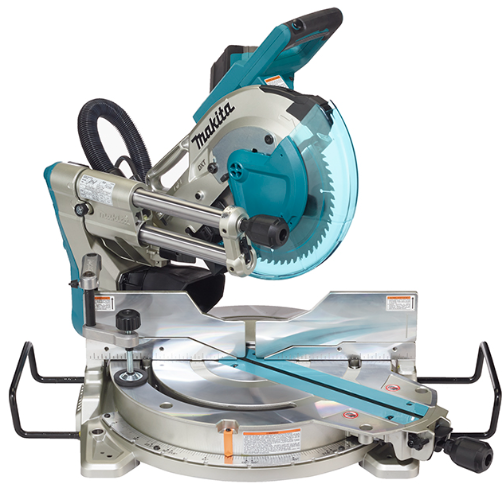
makita LS1019 Slide Compound Miter Saw


SPECIFICATIONS
Model: |
LS1019 | LS1019L | |
| Blade diameter | European countries | 260 mm | |
| Countries other than Europe | 255 mm – 260 mm | ||
| Hole diameter | European countries | 30 mm | |
| Countries other than Europe | 25.4 mm | ||
| Max. kerf thickness of the saw blade | 3.2 mm | ||
| Max. miter angle | Right 60°, Left 60° | ||
| Max. bevel angle | Right 48°, Left 48° | ||
| No load speed (RPM) | 3,200 min-1 | ||
| Laser type | – | Red Laser 650 nm, Maximum output 1.6mW (Laser Class 2M ) | |
| Dimensions (L x W x H) | 805 mm x 644 mm x 660 mm | ||
| Net weight | 26.1 kg | 26.3 kg | |
Cutting capacities for special cuttings
| Miter angle | Bevel angle | ||
| 45° (left) | 0° | 45° (right) | |
| 0° | 42 mm x 310 mm 58 mm x 279mm | 68 mm x 310 mm 91 mm x 279 mm | 29 mm x 310 mm 43 mm x 279 mm |
| 45° (right and left) | 42 mm x 218 mm 58 mm x 197 mm | 68 mm x 218 mm 91 mm x 197 mm | 29 mm x 218 mm 43 mm x 197 mm |
| 60° (right and left) | – | 68 mm x 155 mm 91 mm x 139 mm | – |
- Due to our continuing program of research and development, the specifications herein are subject to change without notice.
- Specifications may differ from country to country.
- Weight according to EPTA-Procedure 01/2014
Symbols
The followings show the symbols which may be used for the equipment. Be sure that you understand their meaning before use.


Intended use
The tool is intended for accurate straight and miter cutting in wood. With appropriate saw blades, aluminum can also be sawed.
Power supply
The tool should be connected only to a power supply of the same voltage as indicated on the nameplate, and can only be operated on single-phase AC supply. They are double-insulated and can, therefore, also be used from sockets without earth wire.
Noise
The typical A-weighted noise level determined according to EN62841-3-9:
- Model LS1019
Sound pressure level (LpA) : 91 dB(A) Sound power level (LWA) : 101 dB (A) Uncertainty (K) : 3 dB(A) - Model LS1019L
Sound pressure level (LpA) : 91 dB(A) Sound power level (LWA) : 101 dB (A) Uncertainty (K) : 3 dB(A)
NOTE: The declared noise emission value(s) has been measured in accordance with a standard test method and may be used for comparing one tool with another.
NOTE: The declared noise emission value(s) may also be used in a preliminary assessment of exposure.
WARNING: Wear ear protection.
WARNING: The noise emission during actual use of the power tool can differ from the declared value(s) depending on the ways in which the tool is used especially what kind of workpiece is processed.
WARNING: Be sure to identify safety measures to protect the operator that are based on an estimation of exposure in the actual conditions of use (tak-ing account of all parts of the operating cycle such as the times when the tool is switched off and when it is running idle in addition to the trigger time).
Vibration
The vibration total value (tri-axial vector sum) deter-mined according to EN62841-3-9:
- Model LS1019
Vibration emission (ah) : 2.5 m/s2 or less Uncertainty (K) : 1.5 m/s2 - Model LS1019L
Vibration emission (ah) : 2.5 m/s2 or less Uncertainty (K) : 1.5 m/s2
NOTE: The declared vibration total value(s) has been measured in accordance with a standard test method and may be used for comparing one tool with another.
NOTE: The declared vibration total value(s) may also be used in a preliminary assessment of exposure.
WARNING: The vibration emission during actual use of the power tool can differ from the declared value(s) depending on the ways in which the tool is used especially what kind of workpiece is processed.
WARNING: Be sure to identify safety measures to protect the operator that are based on an estimation of exposure in the actual conditions of use (taking account of all parts of the operating cycle such as the times when the tool is switched off and when it is running idle in addition to the trigger time).
EC Declaration of Conformity
For European countries only
The EC declaration of conformity is included as Annex A to this instruction manual.
SAFETY WARNINGS
General power tool safety warnings
WARNING: Read all safety warnings, instructions, illustrations and specifications provided with this power tool. Failure to follow all instructions listed below may result in electric shock, fire and/or serious injury. Save all warnings and instructions for future reference. The term “power tool” in the warnings refers to your mains-operated (corded) power tool or battery-operated (cordless) power tool.
Safety instructions for mitre saws
- Mitre saws are intended to cut wood or wood like products, they cannot be used with abrasive cut-off wheels for cutting ferrous material such as bars, rods, studs, etc. Abrasive dust causes moving parts such as the lower guard to jam. Sparks from abrasive cutting will burn the lower guard, the kerf insert and other plastic parts.
- Use clamps to support the workpiece whenever possible. If supporting the workpiece by hand, you must always keep your hand at least 100 mm from either side of the saw blade. Do not use this saw to cut pieces that are too small to be securely clamped or held by hand. If your hand is placed too close to the saw blade, there is an increased risk of injury from blade contact.
- The workpiece must be stationary and clamped or held against both the fence and the table. Do not feed the workpiece into the blade or cut “freehand” in any way. Unrestrained
or moving workpieces could be thrown at high speeds, causing injury. - Push the saw through the workpiece. Do not pull the saw through the workpiece. To make a cut, raise the saw head and pull it out over the workpiece without cutting, start the motor, press the saw head down and push the saw through the workpiece. Cutting on the pull stroke is likely to cause the saw blade to climb on top of the workpiece and violently throw the blade assembly towards the operator.
- Never cross your hand over the intended line of cutting either in front or behind the saw blade. Supporting the workpiece “cross handed” i.e. hold-ing the workpiece to the right of the saw blade with your left hand or vice versa is very dangerous.
- Fig.1
- Do not reach behind the fence with either hand closer than 100 mm from either side of the saw blade, to remove wood scraps, or for any other reason while the blade is spinning. The proximity of the spinning saw blade to your hand may not be obvious and you may be seriously injured.
- Inspect your workpiece before cutting. If the workpiece is bowed or warped, clamp it with the outside bowed face toward the fence. Always make certain that there is no gap between the workpiece, fence and table along the line of the cut. Bent or warped workpieces can twist or shift and may cause binding on the spinning saw blade while cutting. There should be no nails or foreign objects in the workpiece.
- Do not use the saw until the table is clear of all tools, wood scraps, etc., except for the work-piece. Small debris or loose pieces of wood or other objects that contact the revolving blade can be thrown with high speed.
- Cut only one workpiece at a time. Stacked multiple workpieces cannot be adequately clamped or braced and may bind on the blade or shift during cutting.
- Ensure the mitre saw is mounted or placed on a level, firm work surface before use. A level and firm work surface reduces the risk of the mitre saw becoming unstable.
- Plan your work. Every time you change the bevel or mitre angle setting, make sure the adjustable fence is set correctly to support the workpiece and will not interfere with the blade or the guarding system. Without turning the tool “ON” and with no workpiece on the table, move the saw blade through a complete simulated cut to assure there will be no interference or danger of cutting the fence.
- Provide adequate support such as table extensions, saw horses, etc. for a workpiece that is wider or longer than the table top. Workpieces longer or wider than the mitre saw table can tip
if not securely supported. If the cut-off piece or workpiece tips, it can lift the lower guard or be thrown by the spinning blade. - Do not use another person as a substitute for a table extension or as additional support. Unstable support for the workpiece can cause the blade to bind or the workpiece to shift during the cutting operation pulling you and the helper into the spinning blade.
- The cut-off piece must not be jammed or pressed by any means against the spinning saw blade. If confined, i.e. using length stops, the cut-off piece could get wedged against the blade and thrown violently.
- Always use a clamp or a fixture designed to properly support round material such as rods or tubing. Rods have a tendency to roll while being cut, causing the blade to “bite” and pull the work with your hand into the blade.
- Let the blade reach full speed before contacting the workpiece. This will reduce the risk of the workpiece being thrown.
- If the workpiece or blade becomes jammed, turn the mitre saw off. Wait for all moving parts to stop and disconnect the plug from the power source and/or remove the battery pack. Then work to free the jammed material. Continued sawing with a jammed workpiece could cause loss of control or damage to the mitre saw.
- After finishing the cut, release the switch, hold the saw head down and wait for the blade to stop before removing the cut-off piece. Reaching with your hand near the coasting blade is dangerous.
- Hold the handle firmly when making an incomplete cut or when releasing the switch before the saw head is completely in the down position. The braking action of the saw may cause the saw head to be suddenly pulled downward, causing a risk of injury.
- Only use the saw blade with the diameter that is marked on the tool or specified in the manual. Use of an incorrectly sized blade may affect the proper guarding of the blade or guard operation which could result in serious personal injury.
- Only use the saw blades that are marked with a speed equal or higher than the speed marked on the tool.
- Do not use the saw to cut other than wood, aluminum or similar materials.
- (For European countries only)
- Always use the blade which conforms to EN847-1.
Additional instructions
- Make workshop kid proof with padlocks.
- Never stand on the tool. Serious injury could occur if the tool is tipped or if the cutting tool is unintentionally contacted.
- Never leave the tool running unattended. Turn the power off. Do not leave tool until it comes to a complete stop.
- Do not operate saw without guards in place. Check blade guard for proper closing before each use. Do not operate saw if blade guard does not move freely and close instantly. Never clamp or tie the blade guard into the open position.
- Keep hands out of path of saw blade. Avoid contact with any coasting blade. It can still cause severe injury.
- To reduce the risk of injury, return carriage to the full rear position after each crosscut operation.
- Always secure all moving portions before carrying the tool.
- Stopper pin which locks the cutter head down is for carrying and storage purposes only and not for any cutting operations.
- Check the blade carefully for cracks or damage before operation. Replace cracked or damaged blade immediately. Gum and wood pitch hardened on blades slows saw and increases potential for kickback. Keep blade clean by first removing it from tool, then cleaning it with gum and pitch remover, hot water or kerosene. Never use gasoline to clean blade.
- While making a slide cut, KICKBACK can occur. KICKBACK occurs when the blade binds in the workpiece during a cutting operation and the saw blade is driven rapidly towards the operator. Loss of control and serious personal injury can result. If blade begins to bind during a cutting operation, do not continue to cut and release switch immediately.
- Use only flanges specified for this tool.
- Be careful not to damage the arbor, flanges (especially the installing surface) or bolt. Damage to these parts could result in blade breakage.
- Make sure that the turn base is properly secured so it will not move during operation. Use the holes in the base to fasten the saw to a stable work platform or bench. NEVER use tool where operator positioning would be awkward.
- Make sure the shaft lock is released before the switch is turned on.
- Be sure that the blade does not contact the turn base in the lowest position.
- Hold the handle firmly. Be aware that the saw moves up or down slightly during start-up and stopping.
- Make sure the blade is not contacting the workpiece before the switch is turned on.
- Before using the tool on an actual workpiece, let it run for a while. Watch for vibration or wobbling that could indicate poor installation or a poorly balanced blade.
- Stop operation immediately if you notice any-thing abnormal.
- Do not attempt to lock the trigger in the “ON” position.
- Always use accessories recommended in this manual. Use of improper accessories such as abrasive wheels may cause an injury.
- Some material contains chemicals which may be toxic. Take caution to prevent dust inhalation and skin contact. Follow material supplier safety data.
Additional safety rules for the laser
- 1. LASER RADIATION, DO NOT STARE INTO THE BEAM OR VIEW DIRECTLY WITH OPTICAL INSTRUMENTS, CLASS 2M LASER PRODUCT.
SAVE THESE INSTRUCTIONS.
WARNING: DO NOT let comfort or familiarity with product (gained from repeated use) replace strict adherence to safety rules for the subject product. MISUSE or failure to follow the safety rules stated in this instruction manual may cause serious personal injury.
PARTS DESCRIPTION
| 1 | Slide pole | 2 | Stopper pin (for carriage sliding) | 3 | Vertical vise | 4 | Releasing button (for right side bevel angle) |
| 5 | Holder | 6 | Turn base | 7 | Pointer (for miter angle) | 8 | Miter angle scale |
| 9 | Kerf board | 10 | Blade case | 11 | Adjusting screw (for laser line) | 12 | Range adjustment screw (for laser line) |
| 13 | Blade guard | 14 | Knob (for bevel angle) | 15 | Hex wrench | 16 | Adjusting screw (for lower limit position) |
| 17 | Adjusting bolt (for maxi- mum cutting capacity) | 18 | Stopper arm | 19 | Lock lever (for turn base) | 20 | Releasing lever (for turn base) |
| 21 | Grip (for turn base) | – | – | – | – | – | – |
| 1 | Switch trigger | 2 | Lock-off button | 3 | Hole for padlock | 4 | Switch (for laser line) |
| 5 | Hose (for dust extraction) | 6 | Stopper pin (for carriage elevation) | 7 | Guide fence (lower fence) | 8 | Guide fence (upper fence) |
| 9 | Dust bag | 10 | 0° adjusting bolt (for bevel angle) | 11 | Bevel angle scale | 12 | Releasing lever (for 48° bevel angle) |
| 13 | Latch lever (for bevel angle) | 14 | Pointer (for bevel angle) | 15 | 45° adjusting bolt (fo bevel angle) | – | – |
INSTALLATION
Installing the grip
Screw the threaded shaft of the grip into the turn base.
- Fig.4: 1. Grip
- 2. Turn base
Installing the dust extraction hose
Connect the dust extraction hose to the tool as illustrated. Make sure that the elbow and the sleeve fit properly to the ports of the tool.
- Fig.5: 1. Dust extraction hose
- 2. Elbow
- 3. Sleeve
- 4. Port
To remove the elbow from the port, pull the elbow while pressing down the lock button.
- Fig.6: 1. Lock button
- 2. Elbow
Bench mounting
When the tool is shipped, the handle is locked in the lowered position by the stopper pin. While lowering the handle slightly, pull the stopper pin and rotate it 90°.
- Fig.7: 1. Locked position
- 2. Unlocked position
- 3. Stopper pin
This tool should be bolted with four bolts to a level and stable surface using the bolt holes provided in the tool’s base. This will help prevent tipping and possible injury.
- Fig.8: 1. Bolt
WARNING: Ensure that the tool will not move on the supporting surface. Movement of the miter saw on the supporting surface while cutting may result in loss of control and serious personal injury.
FUNCTIONAL DESCRIPTION
WARNING: Always be sure that the tool is switched off and unplugged before adjusting or checking function on the tool. Failure to switch off and unplug the tool may result in serious personal injury from accidental start-up.
Blade guard
- Fig.9: 1. Blade guard
When lowering the handle, the blade guard rises automatically. The guard is spring loaded so it returns to its original position when the cut is completed and the handle is raised.
WARNING: Never defeat or remove the blade guard or the spring which attaches to the guard. An exposed blade as a result of defeated guarding may result in serious personal injury during operation. In the interest of your personal safety, always maintain the blade guard in good condition. Any irregular operation of the blade guard should be corrected immediately. Check to assure spring loaded return action of guard.
WARNING: Never use the tool if the blade guard or spring are damaged, faulty or removed. Operation of the tool with a damaged, faulty or removed guard may result in serious personal injury.
If the see-through blade guard becomes dirty, or saw-dust adheres to it in such a way that the blade and/or workpiece is no longer easily visible, unplug the saw and clean the guard carefully with a damp cloth. Do not use solvents or any petroleum-based cleaners on the plastic guard because this may cause damage to the guard.
If the blade guard is especially dirty and vision through the guard is impaired, unplug the tool and use the sup-plied wrench to loosen the hex bolt holding the center cover. Loosen the hex bolt by turning it counterclockwise-wise and raise the blade guard and center cover. With the blade guard so positioned, cleaning can be more completely and efficiently accomplished. When cleaning is complete, reverse procedure above and secure bolt. Do not remove spring holding blade guard. If guard becomes discolored through age or UV light exposure, contact a Makita service center for a new guard. DO NOT DEFEAT OR REMOVE GUARD.
- Fig.10: 1. Center cover
- 2. Hex wrench
- 3. Blade guard
Kerf boards
This tool is provided with the kerf boards in the turn base to minimize tearing on the exit side of a cut. The kerf boards are factory adjusted so that the saw blade does not contact the kerf boards. Before use, adjust the kerf boards as follows:
- Fig.11: 1. Kerf board
- Fig.12: 1. Left bevel cut
- 2. Straight cut
- 3. Right level cut
- 4. Saw blade
- 5. Blade teeth
- 6. Kerf board
First, unplug the tool. Loosen all the screws (2 each on left and right) securing the kerf boards until the kerf boards can still be easily moved by hand. Lower the handle fully, then pull and turn the stopper pin to lock the handle in the lowered position. Release the stopper pin on the sliding pole and pull the carriage toward you fully. Adjust the kerf boards so that the kerf boards just contact the sides of the blade teeth. Tighten the front screws (do not tighten firmly). Push the carriage toward the guide fence fully and adjust the kerf boards so that the kerf boards just contact the sides of blade teeth. Tighten the rear screws (do not tighten firmly).
After adjusting the kerf boards, release the stopper pin and raise the handle. Then tighten all the screws securely.
NOTICE: After setting the bevel angle ensure that the kerf boards are adjusted properly. Correct adjustment of the kerf boards will help provide proper support of the workpiece minimizing workpiece tear out.
Maintaining maximum cutting capacity
This tool is factory adjusted to provide the maximum cutting capacity for 255 mm or 260 mm saw blade. When installing a new blade, always check the lower limit position of the blade and if necessary, adjust it as follows:
First, unplug the tool. Turn the stopper lever to engaged position.
- Fig.13: 1. Stopper lever
Push the carriage toward the guide fence fully and lower the handle completely. Adjust the blade position by turning the adjusting bolt with the hex wrench. The periphery of the blade should extend slightly below the top surface of the turn base and also comes to the point where the front face of the guide fence meets the top surface of the turn base.
- Fig.14: 1. Adjusting bolt
- Fig.15: 1. Top surface of turn base
- 2. Periphery of blade
- 3. Guide fence
With the tool unplugged, rotate the blade by hand while holding the handle all the way down to be sure that the blade does not contact any part of the lower base. Re-adjust slightly, if necessary. After adjustment, always return the stopper lever to the original position.
WARNING: After installing a new blade and with the tool unplugged, always be sure that the blade does not contact any part of the lower base when the handle is lowered completely. If a blade makes contact with the base it may cause kickback and result in serious personal injury.
Stopper arm
The lower limit position of the blade can be easily adjusted with the stopper arm. To adjust it, turn the stopper arm in the direction of the arrow as shown in the figure. Turn the adjusting screw so that the blade stops at the desired position when lowering the handle fully.
- Fig.16: 1. Stopper arm
- 2. Adjusting screw
Adjusting the miter angle
CAUTION: After changing the miter angle, always secure the turn base by tightening the grip firmly.
NOTICE: When turning the turn base, be sure to raise the handle fully.
- Fig.17: 1. Lock lever
- 2. Grip
- 3. Releasing lever
- 4. Pointer
Rotate the grip counterclockwise to unlock the turn base. Turn the grip while holding down the lock lever to move the turn base. Align the pointer with your desired angle on the scale then tighten the grip.
NOTE: If you depress the releasing lever, you can move the turn base without holding down the lock lever. Tighten the grip at your desired position.
This miter saw employs positive stop function. You can set 0°, 15°, 22.5°, 31.6°, 45°, and 60° right/left miter angle quickly. To use this function, move the turn base close to your desired positive stop angle while holding down the lock lever. Then release the lock lever and move the turn base to your desired positive stop angle until the turn base is locked.
Adjusting the bevel angle
NOTICE: Always remove the upper guide fences and vertical vise before adjusting the bevel angle.
NOTICE: When changing bevel angles, be sure to position the kerf boards appropriately as explained in the “Kerf boards” section.
NOTICE: When tilting the saw blade, be sure to raise the handle fully.
NOTICE: Do not tighten the knob too hard. Doing so may cause malfunction of the locking mechanism of the bevel angle.
- Turn the knob on the slide pole counterclockwise.
- Fig.18: 1. Knob
- Pull and turn the latch lever to the position as illustrated.
- Fig.19: 1. Latch lever
- Match the pointer with your desired angle on the scale by moving the carriage then tighten the knob.
- Fig.20: 1. Bevel angle scale
- Pointer
To tilt the carriage to the right, tilt the carriage to the left slightly and then tilt it to the right while pressing down the releasing button.
- Fig.21: 1. Releasing button
If you perform a bevel cut greater than 45°, move the carriage while sliding the releasing lever toward the front of the tool. You can perform up to 48° bevel cut.
- Fig.22: 1. Releasing lever
This miter saw employs positive stop function. You can set 22.5° and 33.9° angle to both right and left quickly. Set the latch lever in the position as illustrated and tilt the carriage. To change the angle, pull the latch lever and tilt the carriage.
- Fig.23: 1. Latch lever
CAUTION: After changing the bevel angle, always secure the knob.
Slide lock
To lock the sliding movement of the carriage, push the carriage toward the guide fence until it stops. Pull the stopper pin and rotate it 90°.
- Fig.24: 1. Unlocked position
- 2. Locked position
- 3. Stopper pin
Switch action
WARNING: Before plugging in the tool, always check to see that the switch trigger actuates properly and returns to the “OFF” position when released. Do not pull the switch trigger hard without pressing in the lock-off button. This can cause switch breakage. Operating a tool with a switch that does not actuate properly can lead to loss of control and serious personal injury.
WARNING: NEVER use tool without a fully operative switch trigger. Any tool with an inoperative switch is HIGHLY DANGEROUS and must be repaired before further usage or serious personal injury may occur.
WARNING: NEVER defeat the lock-off button by taping down or some other means. A switch with a negated lock-off button may result in unintentional operation and serious personal injury.
WARNING: NEVER use the tool if it runs when you simply pull the switch trigger without press-ing the lock-off button. A switch in need of repair may result in unintentional operation and serious personal injury. Return tool to a Makita service center for proper repairs BEFORE further usage.
- Fig.25: 1. Switch trigger
- 2. Lock-off button
- 3. Hole for padlock
To prevent the switch trigger from being accidentally pulled, a lock-off button is provided. To start the tool, press in the lock-off button and pull the switch trigger. Release the switch trigger to stop. A hole is provided in the switch trigger for insertion of a padlock to lock the tool off.
WARNING: Do not use a lock with a shank or cable any smaller than 6.35 mm (1/4″) in diameter. A smaller shank or cable may not properly lock the tool in the off position and unintentional operation may occur resulting in serious personal injury.
Electronic function
- Constant speed control
The tool is provided with an electronic speed control which helps maintain a constant blade rotation speed even under load. A constant blade rotation speed will result in a very smooth cut. - Soft start feature
This function allows the smooth start-up of the tool by limiting the start-up torque. - Laser beam action
For model LS1019L only
CAUTION: Never look into the laser beam. Direct laser beam may injure your eyes.
To turn on the laser beam, press the upper position (I) of the switch. To turn off the laser beam, press the lower position (0) of the switch.
- Fig.26: 1. Switch for laser Laser line can be shifted to either the left or right side of the saw blade by turning the adjusting screw as follows.
- Fig.27: 1. Adjusting screw
- Loosen the adjusting screw by turning it counterclockwise.
- With the adjusting screw loosened, slide the adjusting screw to the right or left as far as it goes.
- Tighten the adjusting screw firmly at the position where it stops sliding.
NOTE: Laser line is factory adjusted so that it is positioned within 1 mm from the side surface of the blade (cutting position).
NOTE: When laser line appears dim and hard to see because of direct sunlight, relocate the work area to a place where there is less direct sunlight.
Aligning the laser line
Align the cutting line on your workpiece with the laser line.
- Fig.28
- When you want to obtain the correct size on the left side of workpiece, shift the laser line to the left of the blade.
- When you want to obtain the correct size on the right side of workpiece, shift the laser line to the right of the blade.
NOTE: Use wood facing against the guide fence when aligning the cutting line with the laser line at the side of guide fence in compound cutting (bevel angle 45° and miter angle right 45°).
ASSEMBLY
WARNING: Always be sure that the tool is switched off and unplugged before working on the tool. Failure to switch off and unplug the tool may result in serious personal injury.
Hex wrench storage
When not in use, store the hex wrench as shown in the figure to keep it from being lost.
- Fig.29: 1. Hex wrench
Removing and installing saw blade
WARNING: Always be sure that the tool is switched off and unplugged before installing or removing the blade. Accidental start up of the tool may result in serious personal injury.
WARNING: Use only the Makita wrench pro-vided to install or remove the blade. Failure to use the wrench may result in overtightening or insufficient tightening of the hex socket bolt and serious personal injury.
Always lock the carriage with raised position when removing and installing the blade. Pull the stopper pin and rotate it 90° with the carriage raised.
- Fig.30: 1. Unlocked position
- 2. Locked position
- 3. Stopper pin
Removing the blade
Loosen the hex bolt holding the center cover using the hex wrench. Raise the blade guard and center cover.
- Fig.31: 1. Center cover
- 2. Hex wrench
- 3. Blade guard
Press the shaft lock to lock the spindle and use the hex wrench to loosen the hex socket bolt. Then remove the hex socket bolt, outer flange and blade.
- Fig.32: 1. Shaft lock
- 2. Hex wrench
- 3. Hex socket bolt (left-handed)
- 4. Loosen
- 5. Tighten
Installing the blade
Mount the blade carefully onto the spindle, making sure that the direction of the arrow on the surface of the blade matches the direction of the arrow on the blade case.
- Fig.33: 1. Arrow on the blade case
- 2. Arrow on the blade
Install the outer flange and hex socket bolt. Tighten the hex socket bolt counterclockwise using the hex wrench while pressing the shaft lock.
- Fig.34: 1. Hex socket bolt
- 2. Outer flange
- 3. Saw blade
- 4. Inner flange
- 5. Spindle
- 6. Ring
NOTICE: If the inner flange is removed, be sure to install it on the spindle with its protrusion facing away from the blade. If the flange is installed incorrectly, the flange will rub against the machine. Return the blade guard and center cover to its original position. Then tighten the hex bolt clockwise to secure the center cover. Unlock the stopper pin to release carriage from the raised position. Lower the handle to make sure that the blade guard moves properly. Make sure shaft lock has released spindle before making cut.
WARNING: Before mounting the blade onto the spindle, always be sure that the correct ring for the blade’s arbor hole you intend to use is installed between the inner and the outer flanges. Use of the incorrect arbor hole ring may result in the improper mounting of the blade causing blade movement and severe vibration resulting in possible loss of control during operation and in serious personal injury.
Connecting a vacuum cleaner
When you wish to perform clean cutting operation, connect a Makita vacuum cleaner to the dust nozzle using a front cuff 24 (optional accessory).
- Fig.35: 1. Front cuff 24
- 2. Hose
- 3. Vacuum cleaner
Dust bag
The use of the dust bag makes cutting operations clean and dust collection easy. To attach the dust bag, remove the dust extraction hose from the tool and connect the dust bag.
- Fig.36: 1. Dust extraction hose
- 2. Dust bag
When the dust bag is about half full, remove the dust bag from the tool and pull the fastener out. Empty the dust bag of its contents, tapping it lightly so as to remove particles adhering to the insides which might hamper further collection.
- Fig.37: 1. Fastener
Securing workpiece
WARNING: It is extremely important to always secure the workpiece correctly with the proper type of vise or crown molding stoppers. Failure to do so may result in serious personal injury and cause damage to the tool and/or the workpiece.
WARNING: After a cutting operation, do
not raise the saw blade until it has come to a complete stop. The raising of a coasting blade may result in serious personal injury and damage to the workpiece.
WARNING: When cutting a workpiece that is longer than the support base of the saw, the material should be supported the entire length beyond the support base and at the same height to keep the material level. Proper workpiece support will help avoid blade pinch and possible kickback which may result in serious personal injury. Do not rely solely on the vertical vise and/or horizontal vise to secure the workpiece. Thin material tends to sag. Support workpiece over its entire length to avoid blade pinch and possible KICKBACK.
- Fig.38: 1. Support
- 2. Turn base
Guide fences
WARNING: Before operating the tool, make sure that the upper fence is secured firmly.
WARNING: Before bevel-cutting, make sure that no part of the tool, especially the blade, contacts the upper and lower fences when fully lowering and raising the handle in any position and while moving the carriage through its full range of travel. If the tool or blade makes contact with the fence this may result in kickback or unexpected movement of the material and serious personal injury. Use upper fences to support the material higher than the lower fences. Insert the upper fence into the hole on the lower fence and tighten the clamping screw.
- Fig.39: 1. Upper fence
- 2. Lower fence
- 3. Clamping screw
- 4. Adjusting screw
NOTICE: The lower fences are fixed to the base in the factory. Do not remove the lower fences.
NOTICE: If the upper fence is still loose after tightening the clamping screw, turn the adjusting screw to close a gap. The adjusting screw is factory adjusted. You don’t need to use it unless needed.
You can store the upper fences onto the holder when not in use. Use the clip on the upper fence to hold it on the holder.
- Fig.40: 1. Holder
- 2. Upper fence
- 3. Clip
Vertical vise
WARNING: The workpiece must be secured firmly against the turn base and guide fence with the vise during all operations. If the workpiece is not properly secured against the fence the material may move during the cutting operation causing possible damage to the blade, causing the material to be thrown and loss of control resulting in serious personal injury.
- Fig.41: 1. Vise arm
- 2. Vise rod
- 3. Clamping screw
- 4. Vise knob
The vertical vise can be installed in two positions on either the left or right side of the base. Insert the vise rod into the hole in the base.
Position the vise arm according to the thickness and shape of the workpiece and secure the vise arm by tightening the screw. If the clamping screw contacts the carriage, install it on the opposite side of vise arm. Make sure that no part of the tool contacts the vise when lowering the handle all the way. If some part contacts the vise, re-position the vise. Press the workpiece flat against the guide fence and the turn base. Position the workpiece at the desired cutting position and secure it firmly by tightening the vise knob.
NOTE: For a quick setting of workpiece, turning the vise knob to 90° counterclockwise allows the vise knob to be moved up and down. To secure the work-piece after setting, turn the vise knob clockwise.
Horizontal vise
WARNING: Always rotate the vise nut clock-wise until the workpiece is properly secured. If the workpiece is not properly secured, the material may move during the cutting operation causing possible damage to the saw blade, causing the material to be thrown and loss of control resulting in serious per-sonal injury.
WARNING: When cutting a thin workpiece, such as base boards, against the fence, always use the horizontal vise.
CAUTION: When cutting the workpiece of the thickness 20 mm or thinner, make sure to use a spacer block to secure the workpiece.
The horizontal vise can be installed in two positions on either the left or right side of the base. When performing 22.5° or greater miter cuts, install the horizontal vise on the side opposite the direction in which the turn base is to be turned.
- Fig.42: 1. Vise plate
- 2. Vise nut
- 3. Vise knob
By flipping the vise nut counterclockwise, the vise is released, and rapidly moves in and out. To grip the workpiece, push the vise knob forward until the vise plate contacts the workpiece and flip the vise nut clock-wise. Then turn the vise knob clockwise to secure the workpiece.
NOTE: The maximum width of workpiece which can be secured by the horizontal vise is 228 mm.
Holders
WARNING: Always support a long workpiece so it is level with the top surface of the turn base for an accurate cut and to prevent dangerous loss of tool control. Proper workpiece support will help avoid blade pinch and possible kickback which may result in serious personal injury.
To hold long workpieces horizontally, holders are pro-vided on both sides of the tool. Loosen the screws and extend the holders to the appropriate length for holding the workpiece. Then tighten the screws.
- Fig.43: 1. Holder
- 2. Screw
OPERATION
This tool is intended to cut wood products. With appropriate Makita genuine saw blades, following materials can also be sawed :
- Aluminum products
Refer to our website or contact your local Makita dealer for the correct circular saw blades to be used for the material to be cut.
- WARNING: Make sure the saw blade is not contacting the workpiece, etc. before the switch is turned on. Turning the tool on with the blade in contact with the workpiece may result in kickback and serious personal injury.
- WARNING: After a cutting operation, do not raise the saw blade until it has come to a complete stop. The raising of a coasting blade may result in serious personal injury and damage to the workpiece.
- WARNING: Do not perform any adjustment such as turning grip, knob, and levers on the tool while the saw blade is rotating. Adjustment while the blade is rotating may result in serious personal injury.
- CAUTION: Do not release the saw head uncontrolled from the fully down position. Uncontrolled saw head may hit you and it will result in personal injury.
- NOTICE: Before use, be sure to unlock the stopper pin and release the handle from the lowered position.
- NOTICE: Do not apply excessive pressure on the handle when cutting. Too much force may result in overload of the motor and/or decreased cutting efficiency. Press down handle with only as much force as necessary for smooth cutting and without significant decrease in blade speed.
- NOTICE: Gently press down the handle to per-form the cut. If the handle is pressed down with force or if lateral force is applied, the blade may vibrate and leave a mark (saw mark) in the workpiece and the precision of the cut may be impaired.
- NOTICE: During a slide cut, gently push the carriage toward the guide fence without stopping. If the carriage movement is stopped during the cut, a mark will be left in the workpiece and the precision of the cut will be impaired.
Press cutting
WARNING: Always lock the sliding movement of the carriage when performing a press cutting. Cutting without lock may cause possible kickback which may result in serious personal injury.
- Fig.44: 1. Stopper pin
- Push the carriage toward the guide fence until it stops and lock it with the stopper pin.
- Secure the workpiece with the proper type of vise.
- Switch on the tool without the circular saw blade making any contact and wait until the circular saw blade attains full speed before lowering.
- Gently lower the handle to the fully lowered position to cut the workpiece.
- When the cut is completed, switch off the tool and wait until the circular saw blade has come to a complete stop before returning the circular saw blade to its fully elevated position.
Slide (push) cutting (cutting wide workpieces)
WARNING: Whenever performing a slide cut, first pull the carriage full towards you and press the handle all the way down, then push the car-riage toward the guide fence. Never start the cut with the carriage not pulled fully toward you. If you perform the slide cut without the carriage pulled fully toward you, unexpected kickback may occur and serious personal injury may result.
WARNING: Never attempt to perform a slide cut by pulling the carriage towards you. Pulling the carriage towards you while cutting may cause unexpected kickback resulting in possible serious personal injury.
WARNING: Never perform the slide cut with the handle locked in the lowered position.
- Fig.45: 1. Stopper pin
- Unlock the stopper pin so that the carriage can slide freely.
- Secure the workpiece with the proper type of vise.
- Pull the carriage toward you fully.
- Switch on the tool without the saw blade making any contact and wait until the saw blade attains full speed.
- Press the handle down and push the carriage toward the guide fence and through the workpiece.
- When the cut is completed, switch off the tool and wait until the saw blade has come to a complete stop before returning the blade to its fully elevated position.
Miter cutting
Refer to the section for adjusting the miter angle.
Bevel cut
WARNING: After setting the blade for a bevel cut, ensure that the carriage and saw blade will have free travel throughout the entire range of the intended cut before operating the tool. Interruption of the carriage or blade travel during the cutting operation may result in kickback and serious personal injury.
WARNING: While making a bevel cut, keep hands out of the path of the saw blade. The angle of the blade may confuse the operator as to the actual blade path while cutting and contact with the blade will result in serious personal injury.
WARNING: The saw blade should not be raised until it has come to a complete stop. During a bevel cut, the piece cut off may come to rest against the saw blade. If the blade is raised while it is rotating, the cut-off piece may be ejected by the blade causing the material to fragment which may result in serious personal injury.
NOTICE: When pressing down the handle, apply pressure in parallel with the blade. If a force is applied perpendicularly to the turn base or if the pressure direction is changed during a cut, the precision of the cut will be impaired.
- Fig.46
- Remove the upper fence on the side that you are going to tilt the carriage.
- Unlock the stopper pin.
- Adjust the bevel angle according to the procedure explained in the section for bevel angle adjustment. Then tighten the knob.
- Secure the workpiece with a vise.
- Pull the carriage toward you fully.
- Switch on the tool without the blade making any contact and wait until the blade attains full speed.
- Gently lower the handle to the fully lowered position while applying pressure in parallel with the blade and push the carriage toward the guide fence to cut the workpiece.
- When the cut is completed, switch off the tool and wait until the blade has come to a complete stop before returning the blade to its fully elevated position.
Compound cutting
Compound cutting is the process in which a bevel angle is made at the same time in which a miter angle is being cut on a workpiece. Compound cutting can be performed at the angle shown in the table.
Miter angle |
Bevel angle |
| Left and Right 0° – 45° | Left and Right 0° – 45° |
When performing compound cutting, refer to the section for press cutting, slide (push) cutting, miter cutting and bevel cut.
Cutting crown and cove moldings
Crown and cove moldings can be cut on a compound miter saw with the moldings laid flat on the turn base. There are two common types of crown moldings and one type of cove moldings; 52/38° wall angle crown molding, 45° wall angle crown molding and 45° wall angle cove molding.
- Fig.47: 1. 52/38° type crown molding
- 2. 45° type crown molding
- 3. 45° type cove molding
There are crown and cove molding joints which are made to fit “Inside” 90° corners ((a) and (b) in the figure) and “Outside” 90° corners ((c) and (d) in the figure.)

- Inside corner
- Outside corner

- Inside corner
- Outside corner
Measuring
Measure the wall width, and adjust the width of the workpiece according to it. Always make sure that width of the workpiece’s wall contact edge is the same as wall length.
- Fig.48: 1. Workpiece
- 2. Wall width
- 3. Width of the workpiece
- 4. Wall contact edge
Always use several pieces for test cuts to check the saw angles. When cutting crown and cove moldings, set the bevel angle and miter angle as indicated in the table (A) and position the moldings on the top surface of the saw base as indicated in the table (B).
In the case of left bevel cut

- Inside corner
- Outside corner
Table (A)
| – | Molding position in the figure | Bevel angle | Miter angle | ||
| 52/38° type | 45° type | 52/38° type | 45° type | ||
| For inside corner | (a) | Left 33.9° | Left 30° | Right 31.6° | Right 35.3° |
| (b) | Left 31.6° | Left 35.3° | |||
| For outside corner | (c) | ||||
| (d) | Right 31.6° | Right 35.3° | |||
Table (B)
| – | Molding position in the figure | Molding edge against guide fence | Finished piece |
| For inside corner | (a) | Ceiling contact edge should be against guide fence. | Finished piece will be on the Left side of blade. |
| (b) | Wall contact edge should be against guide fence. | ||
| For outside corner | (c) | Finished piece will be on the Right side of blade. | |
| (d) | Ceiling contact edge should be against guide fence. |
Example:
In the case of cutting 52/38° type crown molding for position (a) in the above figure:
- Tilt and secure bevel angle setting to 33.9° LEFT.
- Adjust and secure miter angle setting to 31.6° RIGHT.
- Lay crown molding with its broad back (hidden) surface down on the turn base with its CEILING CONTACT EDGE against the guide fence on the saw.
- The finished piece to be used will always be on the LEFT side of the blade after the cut has been made.
In the case of right bevel cut

- Inside corner
- Outside corner
Table (A)
| – | Molding position in the figure | Bevel angle | Miter angle | ||
| 52/38°
type |
45° type | 52/38°
type |
45° type | ||
| For inside corner | (a) | Right 33.9° | Right 30° | Right 31.6° | Right 35.3° |
| (b) | Left 31.6° | Left 35.3° | |||
| For outside corner | (c) | ||||
| (d) | Right 31.6° | Right 35.3° | |||
Table (B)
| – | Molding position in the figure | Molding edge against guide fence | Finished piece |
| For inside corner | (a) | Wall contact edge should be against guide fence. | Finished piece will be on the Right side of blade. |
| (b) | Ceiling contact edge should be against guide fence. | ||
| For outside corner | (c) | Finished piece will be on the Left side of blade. | |
| (d) | Wall contact edge should be against guide fence. |
Example:
In the case of cutting 52/38° type crown molding for position (a) in the above figure:
- Tilt and secure bevel angle setting to 33.9° RIGHT.
- Adjust and secure miter angle setting to 31.6° RIGHT.
- Lay crown molding with its broad back (hidden) surface down on the turn base with its WALL CONTACT EDGE against the guide fence on the saw.
- The finished piece to be used will always be on the RIGHT side of the blade after the cut has been made.
Crown molding stopper
Optional accessory
Crown molding stoppers allow easier cuts of crown molding without tilting the saw blade. Install them on the turn base as shown in the figures.
At right 45° miter angle
- Fig.49: 1. Crown molding stopper L
- 2. Crown molding stopper R
- 3. Turn base
- 4. Guide fence At left 45° miter angle
- Fig.50: 1. Crown molding stopper L
- 2. Crown molding stopper R
- 3. Turn base
- 4. Guide fence
Position crown molding with its WALL CONTACT EDGE against the guide fence and its CEILING CONTACT EDGE against the crown molding stoppers as shown in the figure. Adjust the crown molding stoppers according to the size of the crown molding. Tighten the screws to secure the crown molding stoppers. Refer to the table (C) for the miter angle.
- Fig.51: 1. Guide fence
- 2. Crown molding stopper

- Inside corner
- Outside corner
Table (C)
| – | Molding position in the figure | Miter angle | Finished piece |
| For inside corner | (a) | Right 45° | Save the right side of blade |
| (b) | Left 45° | Save the left side of blade | |
| For outside corner | (c) | Save the right side of blade | |
| (d) | Right 45° | Save the left side of blade |
Cutting aluminum extrusion
- Fig.52: 1. Vise
- 2. Spacer block
- 3. Guide fence
- 4. Aluminum extrusion
- 5. Spacer block
When securing aluminum extrusions, use spacer blocks or pieces of scrap as shown in the figure to prevent deformation of the aluminum. Use a cutting lubricant when cutting the aluminum extrusion to prevent build-up of the aluminum material on the circular saw blade.
WARNING: Never attempt to cut thick or round aluminum extrusions. Thick or round aluminum extrusions can be difficult to secure and the work may loosen during the cutting operation which may result in loss of control and serious personal injury.
Groove cutting
WARNING: Do not attempt to perform this type of cut by using a wider type blade or dado blade. Attempting to make a groove cut with a wider blade or dado blade could lead to unexpected cutting results and kickback which may result in serious personal injury.
WARNING: Be sure to return the stopper arm to the original position when performing other than groove cutting. Attempting to make cuts with the stopper arm in the incorrect position could lead to unexpected cutting results and kickback which may result in serious personal injury.
For a dado type cut, perform as follows:
- Adjust the lower limit position of the circular saw blade using the adjusting screw and the stopper arm to limit the cutting depth of the circular saw blade. Refer to the section for stopper arm.
- After adjusting the lower limit position of the circular saw blade, cut parallel grooves across the width of the workpiece using a slide (push) cut.
- Fig.53: 1. Cut grooves with blade
- Remove the workpiece material between the grooves with a chisel.
Carrying tool
Before carrying, make sure to unplug and all movable parts of the miter saw are secured. Always check the following:
- The tool is unplugged.
- The carriage is at 0° bevel angle position and secured.
- The carriage is lowered and locked.
- The carriage is fully slid to the guide fence and locked.
- The turn base is at the full right miter angle position and secured.
- The holders are stored and secured.
Carry the tool by holding both sides of the tool base as shown in the figure.
- Fig.54
WARNING: Stopper pin for carriage elevation is for carrying and storage purposes only and not for any cutting operations. The use of the stopper pin for cutting operations may cause unexpected movemen