Bosch GSR 12V-15 FC Professional Cordless Drill/Driver Instruction Manual


GSR 12V-15 FC Professional


Original instructions


Safety Instructions
General Power Tool Safety Warnings
Read all safety warnings, instructions, illustrations, and specifications provided with this power tool. Failure to follow all instructions listed below may result in electric shock, fire, and/ or serious injury.
Save all warnings and instructions for future reference.
The term “power tool” in the warnings refers to your mains-operated (corded) power tool or battery-operated (cordless) power tool.

Work area safety

Electrical safety
Personal safety
Power tool use and care
Battery tool use and care
Service
Safety information for screwdrivers
Safety instructions for all operations
Safety instructions when using long drill bits
Additional safety information
overloaded.

Product Description and Specifications
Read all the safety and general instructions.
Failure to observe the safety and general instructions may result in electric shock, fire, and/or serious injury.
Please observe the illustrations at the beginning of this operating manual.
Intended use
The power tool is intended for driving and loosening screws and for drilling in wood, metal, and plastic.
The power tool can be used with an angle adapter (GFA 12W), off-set angle adapter (GFA 12-E), bit holder adapter
(GFA 12-X) or drill chuck adapter (GFA 12-B).
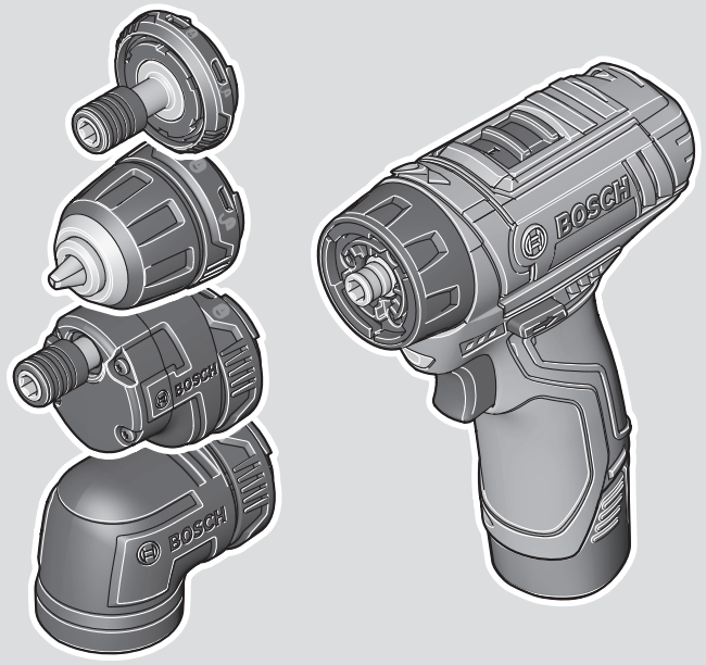
Product features
The numbering of the product features refers to the diagram of the power tool on the graphics page.
- Tool holder
- Torque presetting ring
- Gear selector switch
- Battery release button (2x)
- Rechargeable battery a)
- Rotational direction switch
- On/off switch
- Battery charge indicator
- Worklight
- Bit holder adapter GFA 12-Xa)
- Drill chuck adapter GFA 12-Ba)
- Off-set angle adapter GFA 12-Ea)
- Angle adapter GFA 12-Wa)
- Locking ring
- Handle (insulated gripping surface)
- Universal bit holdera)
a) Accessories shown or described are not included with the product as standard. You can find the complete selection of accessories in our accessories range.
Technical data
| Cordless Drill/Driver | GSR 12V-15 FC | GFA 12-X | GFA 12-B | GFA 12-E | GFA 12-W |
| Article number | 3 601 JF6 0.. | – – |
– – |
– – |
– – | |
| Rated voltage | V= | 12 | – | – | – | – |
| – First gear – Second gear |
min-1 min-1 |
0–400 0–1300 |
– – |
– – |
– – |
– – |
| Max. torque, soft screwdriving application according to ISO 5393A) | Nm | 15 | – – |
– – |
– – |
– – |
| Max. torque, hard screwdriving application according to ISO 5393A) | Nm | 30 | – | – | – | – |
| – Wood – Steel |
mm mm |
19 10 |
– – |
– – |
– – |
– – |
| Max. screw diameter | mm | 7 | – | – | – | – |
| Tool holder | 6.35 (¼”) | 6.35 (¼”) | 1–10 | 6.35 (¼”) | 6.35 (¼”) | |
| Weight according to EPTA-Proced- ure 01:2014 |
kg | 0.8–1.1B) | 0.1 | 0.2 | 0.3 | 0.3 |
| Recommended ambient temperature during charging | °C | 0 to +35 | – – |
– – |
– – |
– – |
| Permitted ambient temperature during operation and during storage | °C | –20 to +50 | – – |
– – |
– – |
– – |
| Recommended re-chargeable batteries | GBA 12V… | – | – | – | – | |
| Recommended char- gers | GAL 12… GAX 18… |
– | – | – | – |
A) measured at 20–25 °C with rechargeable battery GBA 12V 4.0Ah.
B) measured with GBA 12V 2.0Ah and GBA 12V 6.0Ah
Noise/Vibration Information
GSR 12V-15 FC GFA 12-X GFA 12-B GFA 12-E GFA 12-W
Noise emission values were determined according to EN 62841-2-1 for the adapter GFA 12-B.
Noise emission values were determined according to EN 62841-2-2 for the rest of the adapters listed here.
Typically, the A-weighted noise level of the power tool is:
| Sound pressure level | dB(A) | 71,5 | – | – | – | – |
| Sound power level | dB(A) | 82,5 | – | – | – | – |
| Uncertainty K | dB | 3 | 3 | 5 | 3 | 3 |
| Wear hearing protection! |
Vibration total values ah (triax vector sum) and uncertainty K were determined according to EN 62841-2-1 for the adapter GFA 12B.
Vibration total values ah (triax vector sum) and uncertainty K are determined according to EN 62841-2-2 for the rest of the adapters listed here.
Drilling into metal:
| ah K |
m/s2 m/s2 |
– – |
– – |
1.0 1.5 |
– – |
– – |
Screwdriving:
| ah K |
m/s2 m/s2 |
– – |
< 2.5 1.5 |
– – |
< 2.5 1.5 |
< 2.5 1.5 |
The vibration level and noise emission value is given in these instructions have been measured in accordance with a standardized measuring procedure and may be used to compare power tools. They may also be used for a preliminary estimation of vibration and noise emissions.
The stated vibration level and noise emission value represent the main applications of the power tool. However, if the power tool is used for other applications, with different application tools, or is poorly maintained, the vibration level and noise emission value may differ. This may significantly increase the vibration and noise emissions over the total working period.
To estimate vibration and noise emissions accurately, the times when the tool is switched off or when it is running but not actually being used should also be taken into account. This may significantly reduce vibration and noise emissions over the total working period.
Implement additional safety measures to protect the operator from the effects of vibration, such as servicing the power tool and application tools, keeping their hands warm, and organizing workflows correctly.
Fitting
Charging the battery
Note: The battery is supplied partially charged. To ensure full battery capacity, fully charge the battery in the charger before using your power tool for the first time.
The lithium-ion battery can be charged at any time without reducing its service life. Interrupting the charging process does not damage the battery.
The lithium-ion battery is protected against deep discharge by the “Electronic Cell Protection (ECP)”. When the battery is discharged, the power tool is switched off by means of a protective circuit: The application tool no longer rotates.
Removing the battery (see figure A)
To remove the battery (5), press the release button (4) and pull the battery downwards out of the power tool. Do not use force to do this.
Changing the tool
Inserting the application tool (see figure B)
Insert the application tool all the way into the mounting (1).
Fitting the adapter (see figure C)
Remove the application tool.
Insert the adapter into the holder (1). Turn the locking ring (14) until it audibly engages.
Inserting the application tool into the adapter GFA 12-E, and GFA 12-X (see figure D)
Insert the application tool all the way into the mounting (1).
The application tool is held in the mounting by means of a magnet.
GFA 12-B (see figure E)
Open the drill chuck adapter (11) by turning it in direction of rotation ➊ until the application tool can be inserted. Insert the application tool.
Firmly tighten the sleeve of the drill chuck adapter (11) by turning it by hand in direction of rotation ➋. This will automatically lock the drill chuck.
Turning the adapter (see figure F)
Pull the locked adapter approx. 5 mm away from the power tool. Turn the adapter to the required position and then let it go.
Removing the adapter (see figure G)
Remove the application tool.
Unlock the adapter in the
Dust/chip extraction
The dust from materials such as lead paint, some types of wood, minerals, and metal can be harmful to human health.
Touching or breathing in this dust can trigger allergic reactions and/or cause respiratory illnesses in the user or in people in the near vicinity. Certain dust, such as oak or beech dust, are classified as carcinogenic, especially in conjunction with wood treatment additives (chromate, wood preservative). Materials containing asbestos may only be machined by specialists.
– Use a dust extraction system that is suitable for the material wherever possible.
– Provide good ventilation at the workplace.
– It is advisable to wear a P2 filter class breathing mask.
The regulations on the material being machined that apply in the country of use must be observed.

Operation
Start-up
Inserting the battery
Note: The use of batteries unsuitable for your power tool can lead to malfunctions or damage to the power tool.
Set the rotational direction switch (6) to the middle position to avoid unintentionally switching it on. Insert the charged battery (5) into the handle until you feel it engage and it is flush with the handle.
Setting the rotational direction (see figure H)
The rotational direction switch (6) is used to change the rotational direction of the power tool. However, this is not possible while the on/off switch (7) is being pressed.
Right rotation: To drill and drive in screws, press the rotational direction switch (6) through to the left stop.
Left Rotation: To loosen and unscrew screws and nuts, press the rotational direction switch (6) through to the right stop.
Preselecting the Torque
The torque presetting ring (2) can be used to preselect the required torque in 15 stages. When the correct setting is used, the application tool will be stopped when the screw is
driven flush into the material or once the set torque has been reached. In position
When unscrewing screws, it may be advisable to select a higher setting or the

Mechanical gear selection
Gear I:
Low-speed range; for screwdriving or working with a large drilling diameter.
Gear II:
High-speed range; for working with a small drilling diameter.
Switching on/off
To start the power tool, press and hold the on/off switch (7).
The work light (9) lights up when the on/off switch (7) is lightly or fully pressed, allowing the work area to be illuminated in poor lighting conditions.
The work light (9) will remain lit for approximately ten seconds after the on/off switch (7) has been released.
Adjusting the Speed
You can adjust the speed of the power tool when it is on by pressing the on/off switch (7) to vary extents. Light pressure on the on/off switch (7) results in a low rotational speed. Increased pressure on the switch causes an increase in speed.
Fully automatic spindle lock (Auto-Lock)
The drill spindle, and therefore the holder (1), are locked when the on/off switch (7) is not pressed.
This enables screws to be screwed in even when the battery is empty and allows the power tool to be used as a screwdriver.
Temperature-dependent overload protection
In normal conditions of use, the power tool cannot be overloaded. If the power tool is overloaded or not kept within the permitted operating temperature range, the power output is reduced or the power tool is switched off. The power tool will not run at full power output again until the permitted operating temperature has been reached.
Battery charge indicator
When the on/off switch (7) is pressed halfway or completely, the battery charge-control indicator (8) indicates the charge condition of the battery for several seconds. The indicator consists of three green LEDs.
| LEDs | Capacity |
| 3× continuous green light | ≥66 % |
| 2× continuous green light | ≥33 % |
| 1× continuous green light | <33 % |
| 1× flashing green light | Reserve |
Practical advice
After working at a low speed for an extended period, you should operate the power tool at the maximum speed for approximately three minutes without load to cool it down. When drilling into metal, only use sharpened HSS drills (HSS = high-speed steel) which are in perfect condition. The Bosch accessory range guarantees appropriate quality. Before screwing larger, longer screws into hard materials, it is advisable to pre-drill a pilot hole with the core diameter of the thread to approx. 2/3 of the screw length.
Maintenance and Service
Maintenance and Cleaning
After-Sales Service and Application Service
Our after-sales service responds to your questions concerning maintenance and repair of your product as well as spare parts. You can find explosion drawings and information on spare parts at: www.bosch-pt.com
The Bosch product use advice team will be happy to help you with any questions about our products and their accessories.
In all correspondence and spare parts orders, please always include the 10‑digit article number given on the nameplate of the product.
Great Britain
Robert Bosch Ltd. (B.S.C.)
P.O. Box 98
Broadwater Park
North Orbital Road
Denham Uxbridge
UB 9 5HJ
At www.bosch-pt.co.uk you can order spare parts or arrange the collection of a product in need of servicing or repair.
Tel. Service: (0344) 7360109
E-Mail:
You can find further service addresses at: www.bosch-pt.com/serviceaddresses
Transport
The contained lithium-ion batteries are subject to the Dangerous Goods Legislation requirements. The batteries are suitable for road transport by the user without further restrictions. When shipping by third parties (e.g.: by air transport or forwarding agency), special requirements on packaging and labeling must be observed. For the preparation of the item being shipped, consulting an expert for hazardous material is required.
Dispatch battery packs only when the housing is undamaged. Tape or mask off open contacts and pack up the battery in such a manner that it cannot move around in the packaging. Please also observe the possibility of more detailed national regulations.
Disposal


Only for EU countries:
According to the Directive 2012/19/EU, power tools that are no longer usable, and according to the Directive 2006/66/EC, defective or used battery packs/batteries, must be collected separately and disposed of in an environmentally correct manner.
Only for the United Kingdom:
According to Waste Electrical and Electronic Equipment Regulations, 2013 (2013/3113) and the Waste Batteries and Accumulators Regulations 2009 (2009/890), power tools that are no longer usable must be collected separately and disposed of in an environmentally friendly manner.
Battery packs/batteries:
Li-ion:
Please observe the notes in the section on transport (see “Transport”, page 18).
| GSR 12V-15 FC | 3 601 JF6 000 | 2006/42/EC 2014/30/EU 2011/65/EU |
EN 62841-1:2015 EN 62841-2-1:2018+A11:2019 EN 62841-2-2:2014 EN 55014-1:2017+A11:2020 EN 55014-2:2015 EN IEC 63000:2018 |
| * Robert Bosch Power Tools GmbH (PT/ECS) 70538 Stuttgart GERMANY | |||
| Henk Becker Chairman of Executive Management |
Helmut Heinzelmann Head of Product Certification | ||
| Robert Bosch Power Tools GmbH, 70538 Stuttgart, GERMANY Stuttgart, 07.07.2021 | |||


| Cordless Drill/Driver GSR 12V-15 FC |
Article number 3 601 JF6 000 |
| We declare under our sole responsibility that the stated products comply with all applicable provisions of the regulations listed below and are in conformity with the following standards. Technical file at Robert Bosch Ltd. (PT/SOP-GB), Broadwater Park, North Orbital Road, Uxbridge UB9 5HJ, United Kingdom | |
| The Supply of Machinery (Safety) Regulations 2008 The Electromagnetic Compatibility Regulations 2016 The Restriction of the Use of Certain Hazardous Substances in Electrical and Electronic Equipment Regulations 2012 EN 62841-1:2015 EN 62841-2-1:2018+A11:2019| EN 62841-2-2:2014 EN 55014-1:2017+A11:2020 EN 55014-2:2015 EN IEC 63000:2018 | |
| Robert Bosch Power Tools GmbH, 70538 Stuttgart, Germany represented (in terms of the above regulations) by Robert Bosch Limited, Broadwater Park, North Orbital Road, Uxbridge UB9 5HJ, United Kingdom | |
| Vonjy Rajakoba Managing Director – Bosch UK |
Martin Sibley Head of Sales Operations and Aftersales |
| Robert Bosch Ltd. Broadwater Park, North Orbital Road, Uxbridge UB9 5HJ, United Kingdom, as authorized representative acting on behalf of Robert Bosch Power Tools GmbH, 70538 Stuttgart, Germany | |
| Place of issue: Uxbridge | Date of issue: 03/06/2021 |


70538 Stuttgart
GERMANY
www.bosch-pt.com

