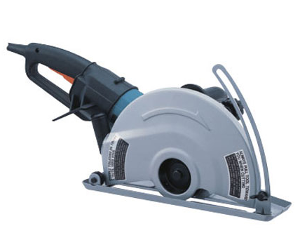
Makita 4112HS Angle Cutter Instruction Manual


Explanation of general view
- Wing bolt
- Base
- Cutting depth
- Clamping nut
- Wheel guard
- Switch trigger
- Lock lever
- Shaft lock
- Socket wrench
- Flange
- Ring
- Wheel
- Flange
- Hex bolt
- Notch
- Cutting line
- Commutator
- Insulating tip
- Carbon brush 20 Dust cover
- Screwdriver
- Brush holder cap 23 Dust nozzle
- Elbow joint
- Hose
SPECIFICATIONS
| Model | 4112S | 4112HS | 4114S |
| Wheel diameter | 305 mm | 355 mm | |
| Max. wheel thickness | 3.5 mm | 3.5 mm | 3.5 mm |
| Max cutting capacity | 100 mm | 125 mm | |
| Rated speed (n)/No load speed (n0) | 3,800 (min–1) | 5,000 (min–1) | 3,800 (min–1) |
| Overall length | 648 mm | 673 mm | |
| Net weight | 10.4 kg | 10.8 kg | |
| Safety class | /II | ||
- Due to our continuing program of research and devel-opment, the specifications herein are subject to change without notice.
- Specifications may differ from country to country.
- Weight according to EPTA-Procedure 01/2014
Intended use
The tool is intended for cutting tracks in concrete walls or cutting in ferrous materials or concrete drainage chan-nels with a diamond wheel but without using water.
Power supply
The tool should be connected only to a power supply of the same voltage as indicated on the nameplate, and can only be operated on single-phase AC supply. They are double-insulated and can, therefore, also be used from sockets without earth wire.
General Power Tool Safety Warnings
WARNING Read all safety warnings and all instructions. Failure to follow the warnings and instructions may result in electric shock, fire and/or serious injury.
Save all warnings and instructions for future refer-ence.
ANGLE CUTTER SAFETY WARNINGS
- The guard provided with the tool must be securely attached to the power tool and positioned for maximum safety, so the least amount of wheel is exposed towards the operator. Position yourself and bystanders away from the plane of the rotating wheel. The guard helps to protect operator from broken wheel fragments and accidental contact with the wheel.
- Use only bonded reinforced or diamond cut-off wheels for your power tool. Just because an accessory can be attached to your power tool, it does not assure safe operation.
- The rated speed of the accessory must be at least equal to the maximum speed marked on the power tool. Accessories running faster than their rated speed can break and fly apart.
- Wheels must be used only for recommended applications. For example: do not grind with the side of cut-off wheel. Abrasive cut-off wheels are intended for peripheral grinding, side forces applied to these wheels may cause them to shatter.
- Always use undamaged wheel flanges that are of correct diameter for your selected wheel. Proper wheel flanges support the wheel thus reducing the possibility of wheel breakage.
- Do not use worn down reinforced wheels from larger power tools. Wheels intended for a larger power tool are not suitable for the higher speed of a smaller tool and may burst.
- The outside diameter and the thickness of your accessory must be within the capacity rating of your power tool. Incorrectly sized accessories can-not be adequately guarded or controlled.
- The arbour size of wheels and flanges must properly fit the spindle of the power tool. Wheels and flanges with arbour holes that do not match the mounting hardware of the power tool will run out of balance, vibrate excessively and may cause loss of control.
- Do not use damaged wheels. Before each use, inspect the wheels for chips and cracks. If power tool or wheel is dropped, inspect for damage or install an undamaged wheel. After inspecting and installing the wheel, position yourself and bystanders away from the plane of the rotating wheel and run the power tool at maximum no load speed for one minute. Damaged wheels will normally break apart during this test time.
- Wear personal protective equipment. Depend-ing on application, use face shield, safety gog-gles or safety glasses. As appropriate, wear dust mask, hearing protectors, gloves and shop apron capable of stopping small abrasive or workpiece fragments. The eye protection must be capable of stopping flying debris generated by vari-ous operations. The dust mask or respirator must be capable of filtrating particles generated by your operation. Prolonged exposure to high intensity noise may cause hearing loss.
- Keep bystanders a safe distance away from work area. Anyone entering the work area must wear personal protective equipment. Fragments of workpiece or of a broken wheel may fly away and cause injury beyond immediate area of operation.
- Hold the power tool by insulated gripping sur-faces only, when performing an operation where the cutting accessory may contact hidden wiring or its own cord. Cutting accessory contacting a “live” wire may make exposed metal parts of the power tool “live” and could give the operator an elec-tric shock.
- Position the cord clear of the spinning acces-sory. If you lose control, the cord may be cut or snagged and your hand or arm may be pulled into the spinning wheel.
- Never lay the power tool down until the acces-sory has come to a complete stop. The spinning wheel may grab the surface and pull the power tool out of your control.
- Do not run the power tool while carrying it at your side. Accidental contact with the spinning accessory could snag your clothing, pulling the accessory into your body.
- Regularly clean the power tool’s air vents. The motor’s fan will draw the dust inside the housing and excessive accumulation of powdered metal may cause electrical hazards.
- Do not operate the power tool near flammable materials. Sparks could ignite these materials.
- Do not use accessories that require liquid cool-ants. Using water or other liquid coolants may result in electrocution or shock.
Kickback and related warnings
Kickback is a sudden reaction to a pinched or snagged rotating wheel. Pinching or snagging causes rapid stall-ing of the rotating wheel which in turn causes the uncon-trolled power tool to be forced in the direction opposite of the wheel’s rotation at the point of the binding. For example, if an abrasive wheel is snagged or pinched by the workpiece, the edge of the wheel that is entering into the pinch point can dig into the surface of the mate-rial causing the wheel to climb out or kick out. The wheel may either jump toward or away from the operator, depending on direction of the wheel’s movement at the point of pinching. Abrasive wheels may also break under these conditions. Kickback is the result of power tool misuse and/or incor-rect operating procedures or conditions and can be avoided by taking proper precautions as given below.- Maintain a firm grip on the power tool and posi-tion your body and arm to allow you to resist kickback forces. Always use auxiliary handle, if provided, for maximum control over kickback or torque reaction during start-up. The operator can control torque reactions or kickback forces, if proper precautions are taken.
- Never place your hand near the rotating acces-sory. Accessory may kickback over your hand.
- Do not position your body in line with the rotating wheel. Kickback will propel the tool in direction oppo-site to the wheel’s movement at the point of snag-ging.
- Use special care when working corners, sharp edges etc. Avoid bouncing and snagging the accessory. Corners, sharp edges or bouncing have a tendency to snag the rotating accessory and cause loss of control or kickback.
- Do not attach a saw chain, woodcarving blade, segmented diamond wheel with a peripheral gap greater than 10 mm or toothed saw blade. Such blades create frequent kickback and loss of control.
- Do not “jam” the wheel or apply excessive pres-sure. Do not attempt to make an excessive depth of cut. Overstressing the wheel increases the load-ing and susceptibility to twisting or binding of the wheel in the cut and the possibility of kickback or wheel breakage.
- When wheel is binding or when interrupting a cut for any reason, switch off the power tool and hold the power tool motionless until the wheel comes to a complete stop. Never attempt to remove the wheel from the cut while the wheel is in motion otherwise kickback may occur. Investigate and take corrective action to eliminate the cause of wheel binding.
- Do not restart the cutting operation in the work-piece. Let the wheel reach full speed and care-fully re-enter the cut. The wheel may bind, walk up or kickback if the power tool is restarted in the work-piece.
- Support panels or any oversized workpiece to minimize the risk of wheel pinching and kickback. Large workpieces tend to sag under their own weight. Supports must be placed under the workpiece near the line of cut and near the edge of the workpiece on both sides of the wheel.
- Use extra caution when making a “pocket cut” into existing walls or other blind areas. The pro-truding wheel may cut gas or water pipes, electrical wiring or objects that can cause kickback.
- Before using a segmented diamond wheel, makesure that the diamond wheel has the peripheral gap between segments of 10 mm or less, only with a negative rake angle.
Additional Safety Warnings: - Be careful not to damage the spindle, the flange (especially the installing surface) or the lock nut. Damage to these parts could result in wheel breakage.
- Make sure the wheel is not contacting the work-piece before the switch is turned on.
- Before using the tool on an actual workpiece, let it run for a while. Watch for vibration or wobbling that could indicate poor installation or a poorly balanced wheel.
- Watch out for flying sparks. Hold the tool so that sparks fly away from you and other persons or flammable materials.
- Do not leave the tool running. Operate the tool only when hand-held.
- Do not touch the workpiece immediately after operation; it may be extremely hot and could burn your skin.
- Always be sure that the tool is switched off and unplugged or that the battery cartridge is removed before carrying out any work on the tool.
- Observe the instructions of the manufacturer for correct mounting and use of wheels. Handle and store wheels with care.
- Do not use separate reducing bushings or adap-tors to adapt large hole abrasive wheels.
- Use only flanges specified for this tool.
- Check that the workpiece is properly supported.
- Pay attention that the wheel continues to rotate after the tool is switched off.
- If working place is extremely hot and humid, or badly polluted by conductive dust, use a short-circuit breaker (30 mA) to assure operator safety.
- Do not use the tool on any materials containing asbestos.
- Do not use water or grinding lubricant.
- Ensure that ventilation openings are kept clear when working in dusty conditions. If it should become necessary to clear dust, first disconnect the tool from the mains supply (use non metallic objects) and avoid damaging internal parts.
- Cutting discs must not be subjected to any lat-eral pressure.
SAVE THESE INSTRUCTIONS
WARNING
DO NOT let comfort or familiarity with product (gained from repeated use) replace strict adherence to safety rules for the subject product. MISUSE or failure to follow the safety rules stated in this instruc-tion manual may cause serious personal injury.
FUNCTIONAL DESCRIPTION
CAUTION
- Always be sure that the tool is switched off and unplugged before adjusting or checking function on the tool.

Adjusting the depth of cut (Fig. 1)
Loosen the wing bolt on the depth guide and move the base up or down. At the desired depth of cut, secure the base by tightening the wing bolt.

Securing wheel guard (Fig. 2) CAUTION:
- The wheel guard must be adjusted on the tool so that the closed side of the guard always points toward the operator.
- The wheel guard can be adjusted about 80 degrees, after you loosen the clamping nut. Adjust to the desired angle, then secure the clamping nut.

Switch action (Fig. 3)
CAUTION
- Before plugging in the tool, always check to see that the switch trigger actuates properly and returns to the “OFF” position when released.
For tool with the lock-on switch
To start the tool, simply pull the switch trigger (A direc-tion). Release the switch trigger to stop.
For continuous operation, pull the switch trigger (A direc-tion) and then push in the lock lever (B direction).
To stop the tool from the locked position, pull the switch trigger (A direction) fully, then release it.
For tool with the lock-off switch
To prevent the switch trigger from accidentally pulled, a lock lever is provided.
To start the tool, push in the lock lever (B direction) and then pull the switch trigger (A direction). Release the switch trigger to stop.
For tool with the lock on and lock-off switch
To prevent the switch trigger from accidentally pulled, a lock lever is provided.
To start the tool, push in the lock lever (B direction) and then pull the switch trigger (A direction). Release the switch trigger to stop.
For continuous operation, push in the lock lever, (B direc-tion) pull the switch trigger (A direction) and then push the lock lever (B direction) further in.
To stop the tool from the locked position, pull the switch trigger (A direction) fully, then release it.
ASSEMBLY
CAUTION
- Always be sure that the tool is switched off and unplugged before carrying out any work on the tool.


Installing or removing the wheel (Fig. 4 & 5)
To remove the wheel, depress the shaft lock to hold the shaft stationary, then loosen the hex bolt clockwise with the socket wrench.
To install a wheel, place flange with its partly elevated side facing the tool, and then place ring before installing a wheel onto the spindle (shaft) and another flange with partly elevated side facing outward. Be sure to fully tighten the hex bolt counterclockwise after mounting the new wheel, or operation will be dan-gerous.
CAUTION
- Use only the Makita wrench to install or remove the wheel.
OPERATION
CAUTION:
Be sure to pull the tool when cutting a workpiece.
- Use this tool for straight line cutting only. Cutting curves can cause stress cracks or fragmentation of the dia-mond wheel and abrasive cut-off wheel resulting in possible injury to persons in the vicinity.
- After operation, always switch off the tool and wait until the wheel has come to a complete stop before putting the tool down.
- When cutting concrete blocks, tiles or masonry materi-als, do not make a cut in depth more than 60 mm. When you need to cut a workpiece over 60 mm up to 100 mm, make more than two passes of cuts. The depth of the most efficient cut is about 40 mm.
Hold the tool firmly with both hands. First keep the wheel without making any contact with a workpiece to be cut. Then turn the tool on and wait until the wheel attains full speed.
The cut is made by pulling the tool toward you (not by pushing away from you). Align the notch on the base with your cutting line when performing a cut.
Switch off the tool in the position posed when finishing a cut. Raise the tool after the wheel comes to a complete stop. (Fig. 6)

MAINTENANCE
CAUTION
- Always be sure that the tool is switched off and unplugged before attempting to perform inspection or maintenance.
- Never use gasoline, benzine, thinner, alcohol or the like. Discoloration, deformation or cracks may result.
Dressing diamond wheel
If the cutting action of the diamond wheel begins to diminish, use an old discarded coarse grit bench grinder wheel or concrete block to dress the diamond wheel. To do this, tightly secure the bench grinder wheel or con-crete block and cut in it.


Replacing carbon brushes (Fig. 7 & 8)
When the resin insulating tip inside the carbon brush is exposed to contact the commutator, it will automatically shut off the motor. When this occurs, both carbon brushes should be replaced. Keep the carbon brushes clean and free to slip in the holders. Both carbon brushes should be replaced at the same time. Use only identical carbon brushes.
Pick up an end of the dust cover slightly with hands so that brush holder cap appears.
Use a screwdriver to remove the brush holder caps. Take out the worn carbon brushes, insert the new ones and secure the brush holder caps.
To maintain product SAFETY and RELIABILITY, repairs, any other maintenance or adjustment should be per-formed by Makita Authorized Service Centers, always using Makita replacement parts.
OPTIONAL ACCESSORIES
CAUTION
- These accessories or attachments are recommended for use with your Makita tool specified in this manual. The use of any other accessories or attachments might present a risk of injury to persons. Only use accessory or attachment for its stated purpose.
If you need any assistance for more details regarding these accessories, ask your local Makita Service Center.
- Diamond wheels (Dry type)
- Abrasive cut-off wheels
- Socket wrench 17
- Safety goggle
- Ring 20
- Elbow joint

Connecting to vacuum cleaner (Fig. 9)
When you wish to perform cleaner operation, connect a vacuum cleaner to your tool. Connect a hose of vacuum cleaner to the dust nozzle via an elbow joint (accessory).
NOTE
- Some items in the list may be included in the tool pack-age as standard accessories. They may differ from country to country.
Model 4112S, 4112HS
Sound pressure level (LpA): 102 dB (A) Sound power level (LWA): 113 dB (A) Uncertainty (K): 3 dB (A)
Model 4114S
Sound pressure level (LpA): 103 dB (A) Sound power level (LWA): 114 dB (A) Uncertainty (K): 3 dB (A)
Vibration
The vibration total value (tri-axial vector sum) determined according to EN60745:
Model 4112HS
Work mode: concrete cutting
Vibration emission (ah): 3.5 m/s2 Uncertainty (K): 1.5 m/s2
Model 4112S, 4114S
Work mode: concrete cutting
Vibration emission (ah): 4.0 m/s2 Uncertainty (K): 1.5 m/s2
- The declared vibration emission value has been mea-sured in accordance with the standard test method and may be used for comparing one tool with another.
- The declared vibration emission value may also be used in a preliminary assessment of exposure.
WARNING
- The vibration emission during actual use of the power tool can differ from the declared emission value depending on the ways in which the tool is used.
- Be sure to identify safety measures to protect the oper-ator that are based on an estimation of exposure in the actual conditions of use (taking account of all parts of the operating cycle such as the times when the tool is switched off and when it is running idle in addition to the trigger time).
EC DECLARATION OF CONFORMITY
For European countries only
The EC declaration of conformity is included as Annex A to this instruction manual.