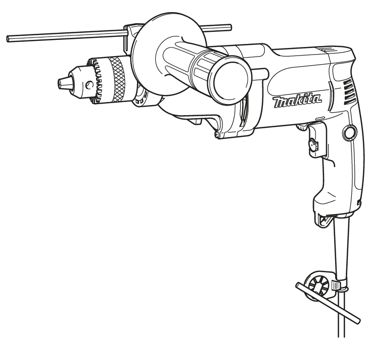
Makita DP4011 2-Speed Drill Instruction Manual


makita DP4011 2-Speed Drill

SPECIFICATIONS
| Model: | DP4010 / DP4011 | ||
| Speed | High | Low | |
| Drilling capacities | Steel | 8 mm | 13 mm |
| Wood | 25 mm | 40 mm | |
| No load speed | 0 – 2,900 min-1 | 0 – 1,200 min-1 | |
| Overall length | 347 mm | ||
| Net weight | 2.3 kg | ||
| Safety class | /II | ||
- Due to our continuing program of research and development, the specifications herein are subject to change without notice.
- Specifications may differ from country to country.
- Weight according to EPTA-Procedure 01/2014
Intended use
The tool is intended for drilling in wood, metal and plastic.
Power supply
The tool should be connected only to a power supply of the same voltage as indicated on the nameplate, and can only be operated on single-phase AC supply. They are double-insulated and can, therefore, also be used from sockets without earth wire.
Noise
The typical A-weighted noise level determined accord-ing to EN62841-2-1:
Sound pressure level (LpA) : 80 dB(A)
Uncertainty (K) : 3 dB(A)
The noise level under working may exceed 80 dB (A).
NOTE: The declared noise emission value(s) has been measured in accordance with a standard test method and may be used for comparing one tool with another.
NOTE: The declared noise emission value(s) may also be used in a preliminary assessment of exposure.
WARNING: Wear ear protection.
WARNING: The noise emission during actual use of the power tool can differ from the declared value(s) depending on the ways in which the tool is used especially what kind of workpiece is processed.
WARNING: Be sure to identify safety mea-sures to protect the operator that are based on an estimation of exposure in the actual conditions of use (taking account of all parts of the operating cycle such as the times when the tool is switched off and when it is running idle in addition to the trigger time).
Vibration
The vibration total value (tri-axial vector sum) deter-mined according to EN62841-2-1: Work mode: drilling into metal Vibration emission (ah,D) : 2.5 m/s2 or less Uncertainty (K) : 1.5 m/s2
NOTE: The declared vibration total value(s) has been measured in accordance with a standard test method and may be used for comparing one tool with another.
NOTE: The declared vibration total value(s) may also be used in a preliminary assessment of exposure.
WARNING: The vibration emission during actual use of the power tool can differ from the declared val-ue(s) depending on the ways in which the tool is used especially what kind of workpiece is processed.
WARNING: Be sure to identify safety measures to protect the operator that are based on an estima-tion of exposure in the actual conditions of use (tak-ing account of all parts of the operating cycle such as the times when the tool is switched off and when it is running idle in addition to the trigger time).
EC Declaration of Conformity
For European countries only The EC declaration of conformity is included as Annex A to this instruction manual.
SAFETY WARNINGS
General power tool safety warnings
WARNING: Read all safety warnings, instruc-tions, illustrations and specifications provided with this power tool. Failure to follow all instructions listed below may result in electric shock, fire and/or serious injury.
Drill safety warnings
- Use the auxiliary handle(s). Loss of control can cause personal injury.
- Hold the power tool by insulated gripping surfaces, when performing an operation where the cutting accessory may contact hidden wir-ing or its own cord. Cutting accessory contacting a “live” wire may make exposed metal parts of the power tool “live” and could give the operator an electric shock.
- Always be sure you have a firm footing. Be sure no one is below when using the tool in high locations.
- Hold the tool firmly.
- Keep hands away from rotating parts.
- Do not leave the tool running. Operate the tool only when hand-held.
- Do not touch the drill bit or the workpiece immediately after operation; they may be extremely hot and could burn your skin.
- Some material contains chemicals which may be toxic. Take caution to prevent dust inhala-tion and skin contact. Follow material supplier safety data.
- If the drill bit cannot be loosened even you open the jaws, use pliers to pull it out. In such a case, pulling out the drill bit by hand may result in injury by its sharp edge.
Safety instructions when using long drill bits
- Never operate at higher speed than the max-imum speed rating of the drill bit. At higher speeds, the bit is likely to bend if allowed to rotate freely without contacting the workpiece, resulting in personal injury.
- Always start drilling at low speed and with the bit tip in contact with the workpiece. At higher speeds, the bit is likely to bend if allowed to rotate freely without contacting the workpiece, resulting in personal injury.
- Apply pressure only in direct line with the bit and do not apply excessive pressure. Bits can bend causing breakage or loss of control, resulting in personal injury.
SAVE THESE INSTRUCTIONS.
WARNING: DO NOT let comfort or familiarity with product (gained from repeated use) replace strict adherence to safety rules for the subject product. MISUSE or failure to follow the safety rules stated in this instruction manual may cause serious personal injury.
FUNCTIONAL DESCRIPTION
CAUTION: Always be sure that the tool is switched off and unplugged before adjusting or checking function on the tool.
Switch action
CAUTION: Before plugging in the tool, always check to see that the switch trigger actuates properly and returns to the “OFF” position when released.
- ► Fig.1: 1. Lock button 2. Speed control screw 3. Switch trigger 4. Higher 5. Lower
To start the tool, simply pull the switch trigger. Tool speed is increased by increasing pressure on the switch trigger. Release the switch trigger to stop. For continuous operation, pull the switch trigger and then push in the lock button. To stop the tool from the locked position, pull the switch trigger fully, then release it. A speed control screw is provided so that maximum tool speed can be limited (variable). Turn the speed control screw clockwise for higher speed, and counterclockwise for lower speed.
Reversing switch action
This tool has a reversing switch to change the direc-tion of rotation. Move the reversing switch lever to the position (A side) for clockwise rotation or to the posi-tion (B side) for counterclockwise rotation.
Speed change
Fig.3: 1. Arrow 2. Speed change knob
Two speed ranges can be preselected with the speed change knob. To change the speed, turn the speed change knob so that the arrow on the tool body points toward the “I” position on the knob for low speed or “II” position for high speed. If it is hard to turn the knob, first turn the chuck slightly in either direction and then turn the knob again.
CAUTION: Use the speed change knob only after the tool comes to a complete stop. Changing the tool speed before the tool stops may damage the tool.
CAUTION: Always set the speed change knob to the correct position. If you operate the tool with the speed change knob positioned halfway between the “I” and “II” position, the tool may be damaged.
ASSEMBLY
CAUTION: Always be sure that the tool is switched off and unplugged before carrying out any work on the tool.
Installing side grip (auxiliary handle)
- Fig.4: 1. Grip base 2. Side grip (auxiliary handle) 3. Teeth 4. Protrusion


Always use the side grip to ensure operating safety. Install the side grip so that the teeth on the grip fit in between the protrusions on the tool barrel. Then tighten the grip by turning clockwise at the desired position.
NOTE: The depth gauge cannot be used at the posi-tion where the depth gauge strikes against the tool body.
Installing or removing drill bit
CAUTION: Always be sure that the tool is switched off and unplugged before installing or removing the drill bit.
To install the drill bit, place it in the drill chuck as far as it will go. Tighten the chuck by hand. Place the chuck key in each of the three holes and tighten clockwise. Be sure to tighten all three chuck holes evenly. To remove the drill bit, turn the drill chuck key counter-clockwise in just one hole, then loosen the chuck by hand.
After using the chuck key, be sure to return it to the original position. For model DP4011 Hold the ring and turn the sleeve counterclockwise to open the chuck jaws. Place the drill bit in the drill chuck as far as it will go. Hold the ring firmly and turn the sleeve clockwise to tighten the chuck. To remove the drill bit, hold the ring and turn the sleeve counterclockwise.
Depth gauge
Optional accessory The depth gauge is convenient for drilling holes of uniform depth. Loosen the side grip and insert the depth gauge into the hole on the side grip. Adjust the depth gauge to the desired depth and tighten the side grip firmly.
NOTE: The depth gauge cannot be used at the posi-tion where the depth gauge strikes against the tool body.
OPERATION
Holding tool
Always use the side grip (auxiliary handle) and firmly hold the tool by side grip and switch handle during operations.
Drilling operation &
Drilling in wood
When drilling in wood, the best results are obtained with wood drills equipped with a guide screw. The guide screw makes drilling easier by pulling the drill bit into the workpiece.
Drilling in metal
To prevent the drill bit from slipping when starting a hole, make an indentation with a center-punch and hammer at the point to be drilled. Place the point of the drill bit in the indentation and start drilling. Use a cutting lubricant when drilling metals. The excep-tions are iron and brass which should be drilled dry.
- CAUTION: Pressing excessively on the tool will not speed up the drilling. In fact, this excessive pressure will only serve to damage the tip of your drill bit, decrease the tool performance and shorten the service life of the tool.
- CAUTION: Hold the tool firmly and exert care when the drill bit begins to break through the workpiece. There is a tremendous force exerted on the tool/drill bit at the time of hole break through.
- CAUTION: A stuck drill bit can be removed simply by setting the reversing switch to reverse rotation in order to back out. However, the tool may back out abruptly if you do not hold it firmly.
- CAUTION: Always secure workpieces in a vise or similar hold-down device.
- CAUTION: Avoid drilling in material that you suspect contains hidden nails or other things that may cause the drill bit to bind or break.
MAINTENANCE
CAUTION: Always be sure that the tool is switched off and unplugged before attempting to perform inspection or maintenance.
NOTICE: Never use gasoline, benzine, thinner, alcohol or the like. Discoloration, deformation or cracks may result.
Cleaning vent holes
The tool and its air vents have to be kept clean. Regularly clean the tool’s air vents or whenever the vents start to become obstructed. To maintain product SAFETY and RELIABILITY, repairs, carbon brush inspection and replacement, any other maintenance or adjustment should be performed by Makita Authorized or Factory Service Centers, always using Makita replacement parts.
OPTIONAL ACCESSORIES
CAUTION: These accessories or attachments are recommended for use with your Makita tool specified in this manual. The use of any other accessories or attachments might present a risk of injury to persons. Only use accessory or attachment for its stated purpose.
If you need any assistance for more details regard-ing these accessories, ask your local Makita Service Center.
- Drill bits
- Hole saws
- Keyless drill chuck
- Chuck key
- Grip assembly
- Depth gauge
- Plastic carrying case
NOTE: Some items in the list may be included in the tool package as standard accessories. They may differ from country to country.