Mitsubishi Electric PAR-WT50R-E ecodan Wireless Remote Controller User Manual


MITSUBISHI ELECTRIC PAR-WT50R-E ecodan Wireless Remote Controller

Safety Precautions
Read thoroughly the following safety precautions before use:
- The following hazardous classification shows the likelihood and severity of hazards if a person does not follow the instructions contained on the following signs.
WARNING: Indicates a hazardous situation which, if a person does not follow the instructions, could result in death or serious injury.
WARNING: Indicates a potentially hazardous situation that, if a person does not follow the instructions, may result in bodily injury or property damage. - Always keep this instruction manual ready at hand for quick reference. Provide this manual to the technician or installer in the event that the device is relocated or repaired. Or, if the ownership changes, hand this manual to the next owner.
WARNING
| Check installation location. | Ensure that the device is placed on a hard and stable place to prevent the device from falling. |
| The device must not be modified or repaired by the user. | Modification or improper repair could cause electrical shock or fire and the like. For repair, contact the dealer where you pur chased the device. |
| Stop operation when the device is malfunctioning. | Operating the malfunctioning device without repairing it could cause breakdown, electrical shock, fire or the like. Should any thing abnormal, such as burning smell, occur, stop operation immediately, turn off power, and contact the dealer. |
| The device must not be dis posed of by the user. | To dispose of the device, contact the dealer. |
| Do not let alkaline batteries become shorted or insert with polarity reversed. Also, do not disassemble, heat, or throw batteries in fire. | Leaked strong alkaline electrolyte could get into your eye, or explode, or generate heat. Injury, burns, or breakdown of the device could result. Should strong alkaline electrolyte come in contact with the skin or clothes, flush electrolyte with clean water. If electrolyte gets into your eye, flush with clean water and seek medical attention immediately. |
CAUTION
| Do not drop the device. | This could break the case or break down the device. |
| Do not wipe the device with benzine, thinner, and a chemical impregnated cloth or the like. | The device could be discolored and damaged. If the dirt is hard to remove, wipe it with a well wrung-out cloth with diluted mild detergent, and dry moisture with a dry cloth. |
| Do not put hazardous materials around the device. | Avoid installing the device in the place where flammable gas may leak. Should leaked gas build up around the device, fire or explosion could occur. |
| Do not disassemble the device. | Direct contact with the control board inside is hazardous and also could result in fire, breakdown, and reduction in operating performance. |
| Do not use the device in particular environments. | Do not use the device in particular environments where the following substances are present in large amounts: oil, vapor, organic solvent, corrosive gas (such as ammonia, sulphuric compounds, and acid or the like) , or where acid or alkali solution, or particular sprays are used frequently. This could affect operating performance, or cause corrosion which could result in electrical shock, breakdown, smoke generation, or fire. (e.g. around kitchen sink, gas cooker, bath room, wash stand or the like) |
| Do not use sharp objects to press the buttons. | Electric shock or breakdown may occur. |
| Do not wash the device with water or solution or the like. | Electric shock or breakdown may occur. |
| Do not touch the device with wet hands. | Electric shock or breakdown may occur. |
| Always observe the operating temperature and humidity requirements. | Always observe the operating temperature and humidity requirements. Otherwise severe damage to the device could result. For more details, refer to the specification table in this manual. |
Observe the following and handle batteries properly. Otherwise it could result in explosion, leak age of electrolytic liquid, or heat generation.
| |
This symbol mark is for EU countries only.
This symbol mark is according to the directive 2002/96/EC Article 10 Information for users and Annex IV, and/or to the directive 2006/66/EC Article 20 Information for end-users and Annex II.
Your MITSUBISHI ELECTRIC product is designed and manufactured with high quality materials and components which can be recycled and/or reused. This symbol means that electrical and electronic equipment, batteries and accumulators, at their end-of-life, should be disposed of separately from your household waste. If a chemical symbol is printed beneath the symbol, this chemical symbol means that the battery or accumulator contains a heavy metal at a certain concentration. This will be indicated as follows: Hg: mercury (0.0005%), Cd; cadmium (0.002 %), PBS: lead (0.004%) In the European Union there are separate collection systems for used electrical and electronic products, batteries and accumulators. Please, dispose of this equipment, batteries and accumulators correctly at your local community waste col lection/recycling center. Please, help us to conserve the environment we live in!
Product Outline
This device is a wireless remote controller system that transmits to the indoor unit at a frequency of 868 MHz The wireless remote controller allows the following settings without leaving your room: room temperature setting, forced DHW mode, and holiday mode.
Following are the features of the wireless remote controller:
- Room temperature is controlled according to the temperature monitored in a selected
- Up to 8 wireless remote controllers
- Holiday mode settings for up to 72 hours on hourly
- Large buttons and easy-to-read LCD
- Floor-to-floor wireless transmission such as from basement to floor
- Each wireless remote controller requires pairing to avoid improper transmission with the unrelated wireless If the wireless remote controller does not go through a pairing process, wireless transmission between the wireless remote controller and the wireless receiver does not work. For more details about pairing, contact your service contractor.
The following operations are disabled when PAR-WT50/WR51 R-E are connected to EH*T20*-*M**A, EH**-*M*A models.
- Cancellation of Forced DHW
- 2-zone temperature control
Included parts
The following items are included in the box.

| Part Name | Quantity |
| Wireless remote controller | 1 |
| Stand | 1 |
| Bracket | 1 |
| Flat head screw 4.1 x 16 | 4 |
| AA alkaline battery | 2 |
| Instruction manual | 1 |
How to read the year of manufacture
The year of manufacture is indicated on the wireless remote controller and receiver as below.
L******SE*****
YEAT of manufacture : 1,2 ,3,4 ,5, 6, 7,8,9,X( 10 ), Y ( 11 ),2( 12)
Year of manufacture (western calendar) 1 =2021, 2=2022
Names of Parts and Functions
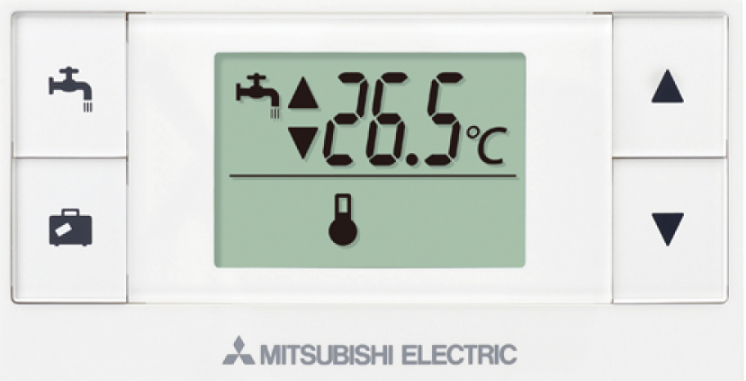
Wireless remote controller buttons/displays
The following explains each button and operation.
All the items above are shown for the purpose of explanation.

| Number | Name | Operation |
| 1 | Forced DHW button | To allow the ecodan system to force start of the DHW mode. |
| 2 | Holiday button | To allow the ecodan system to enter the holiday mode. |
| 3 | Up/ Down button | To adjust room temperatures and set duration time in the holiday mode. |
| 4 | Holiday indicator | To indicate that the ecodan system is remaining in the holiday mode. |
| 5 | DHW indicator | To indicate that the ecodan system is remaining in the forced DHW mode. |
| 6 | Set temp. display | To display the set room temperature. |
7 |
Battery replacement indicator | To indicate when to replace batteries. |
| 8 | Error indicator | To indicate a failure or error, such as a communication error. |
| 9 | Room sensor indicator | The internal temperature sensor in this wireless remote controller monitors the room temperature according to which individual room temperature is controlled. |
| 10 | Room temperature display | To display the room temperature measured by wire less remote controller. |
Before Operation
Remove the battery case cover before placing the wireless remote controller, and place two AA alkaline batteries properly.
- When the wireless remote controller is not paired, it has to go through a pairing process. For details about pairing, contact your service contractor.

Batteries
- When is shown on the display, the batteries are running Replace both of them with two new AA alkaline batteries.
- Do not use Ni-Cd rechargeable batteries.
- The AA alkaline batteries used on the wireless remote controller last for about 1 year under normal usage.
- When not using the wireless remote controller for long periods of time, have the batteries removed.
CAUTION: Always place batteries with correct polarities as indicated in the battery case.

Installation
The wireless remote controller has two methods of installation, using an included bracket or stand.

<< Using a bracket >>

- Determine the position to install the wire less remote controller.
- Fix the bracket with flat head screws.
- Mount the wireless remote controller onto the bracket.
NOTE:
- Avoid over-tightening the screws, which may break or deform the bracket.
- To enhance stability, use all the four screws to secure the bracket.
<<Using a stand >>

- Place the wireless remote controller on the stand.
- Place the stand in proper location.
Location to place the wireless remote controller(s)
Observe the following when determining the installing location.
- Do not place any other electric or electronic appliances within 1 m of the wireless remote controller. (E.g. radio, television, PC, mobile phone or the like.)
- Do not place the wireless remote controller on a metal rack or the like.
- Do not place the wireless remote controller in vicinity of a door or an window.
- Do not place the wireless remote controller near heat or cold sources, such as a radiator or the like.
- Keep the wireless remote controller away from direct sunlight.
- Do not expose the remote controller to a temperature outside the required operating range of 0°C to 40°C.

A room sensor is incorporated in each wireless remote controller. If a remote controller is set as room sensor monitoring the room temperature and the wireless remote controller is placed in an improper location, the desired temperature may not be obtained, so select the location to place the wireless remote controller with great care.
Basic Functions
The following explains the basic functions available on the wireless remote controller.
- <Ecodan system OFF>
- <Ecodan system ON>

- <Zone display>
- When the ecodan system is ON, hold down @ buttons for 3 seconds to display a zone no. assigned to the remote controller.
- Failure or error on the indoor unit, the outdoor unit, or the wireless system When & is shown all the time, this means a failure (or error) on the indoor unit, the outdoor unit, or the wireless system. Contact your service contractor.

Changing Set Temperature
- To increase set temperature: Press (!) button.
- To decrease set temperature: Press(!) button.
- Each press of the buttons adjusts the set temperature by 0.5°C.
- The set temperature range is from 1°C to 30°C.
- When the automatic zone display is active, a zone number assigned to the remote controller is displayed for 3 seconds.
When” – – – 0c” is shown, the ecodan system cannot be operated by remote controller.


When is shown, this indicates that the wireless remote controller is set as room sensor.
<<2-zone temperature control>>
- A thermistor is built in the remote controller (Room RC) or the main controller (Main RC), or TH1. The indoor unit refers to temperature monitored by a selected thermistor and controls temperature for each zone.
- For 2-zone temperature control, one room sensor can be selected for Zone1 and Zone2 separately. The room sensor is used for monitoring room temperature.
- The selection of room sensor can be fixed or changed according to time, using a schedule timer.
Note: Room sensor can be selected by main controller only.

When is shown on the remote controller, this indicates that the remote controller is used for monitoring the room temperature. In this example, the living room temperature monitored by remote controller 1 is regarded as the room temperature for Zone1. The bed room 2 temperature monitored by remote controller 4 is regarded as the room temperature for Zone2.
Forced DHW
Hold down button for 3 seconds or more to allow the indoor unit to enter or exit the forced DHW mode. When the forced DHW mode ends goes out.

When blinks after the button is held down for 3 seconds or more, this indicates that the indoor unit that you use does not support this function.
Holiday Mode
Button allows the indoor unit to enter the holiday mode.

- The holiday button is allowed to set duration of up to 72 hours or no-time-limit (dis played as” – – I-,”).
- The duration is adjusted by 1 hour.
<<Setting>>

- Hold down button for 3 seconds or more. blinks on the screen.
- Press or button to adjust the duration, and press button to save setting. When the set duration shows” – – h “, this indicates that no-time-limit is set. When transmission starts and blink.
- Once the setting is complete stops blinking and lights steadily.
<<Cancelling>>

To cancel the mode, hold down button for 3 seconds or more while the indoor unit is operating in the holiday mode disappears.
<<Communication error>>

When & blinks during operation of the holiday mode, this means a communication error, so please try again.
FAQ
| Fault Symptom | Possible C auses | Solutions |
| The LCD is blank. | No batteries are placed. | Ensure that the batteries are placed in the battery case and no foreign objects are caught between the terminals. |
| Batteries are placed incorrectly. | Check whether the batteries are placed with correct polarities as shown in the battery case. | |
| Batteries are running out. | Replace both with new ones. | |
| is shown. | The batteries are running out, and need replacement. | Replace both with new ones. |
| “OFF” is shown. | The ecodan system is off. | Turn on the ecodan system by main controller again. |
| The wireless remote controller does not work. | Batteries are running out. | Replace both with new ones. |
| Signal is weak. | Find a proper location to operate the wire less remote controller. | |
| Failure or error on the in door unit, the outdoor unit, or the wireless system. | Contact your service contractor. | |
| is shown all the time. | Failure or error on the in door unit, the outdoor unit, or the wireless system. | Contact your service contractor. |
| The desired room temperature is not obtained. | Batteries are running out. | Replace both with new ones. |
| The wireless remote controller is placed in an improper location. | Reposition the wireless remote controller by referring to “Location to place the wireless remote controller(s)” in “4. Before Operation” in this manual. | |
| The wireless remote controller is not set as room sensor. | Contact your service contractor. | |
| Others | Contact your service contractor. |
Specifications
| Item | Description |
| Power source | 3V DC (AA alkaline battery x 2) |
| Operating temperature and humidity requirements | Temperatures: 0 to 40°C Humidifies: 30 to 90%RH (no condensation) |
| Net weight | 200 g (batteries excluded) |
| Dimension (W x H x D) | 140 mm x 75 mm x 18 mm |
| Holiday mode time setting range | 1 to 72 hours or no time limit |
| Display | LCD digital screen |
| Transmitter power level (MAX) | 8dBm |
| Frequency | 868.3 MHz |
Hereby, MITSUBISHI ELECTRIC CORPORATION declares that the radio equipment type PAR-WT50R-E, PARWR51 R-E is in compliance with Directive 2014/53/EU. The full text of the EU declaration of conformity is available at the following internet address:
https://wwwl2.mitsubishielectric.com/
Hereby, MITSUBISHI ELECTRIC CORPORATION declares that the radio equipment type PAR-WT50R-E, PARWR51R-E is in compliance with the Radio Equipment Regulations 2017. The full text of the UK declaration of conformity is available at the following internet address:
https://wwwl2.mitsubishielectric.com/
This product is designed and intended for use in the residential, commercial and light-industrial environment.
Importer:
Mitsubishi Electric Europe B.V.
Capronilaan 46, 1119 NS, Schiphol Rijk, The Netherlands
French Branch
2, Rue De L’Union, 92565 RUEil MAISON Cedex
German Branch
Mitsubishi-Electric-Platz 1 40882 Ratingen North Rhine-Westphalia Germany
Belgian Branch
8210 Loppem, Autobaan 2, Belgium
Irish Branch
Westgate Business Park, Ballymount Road, Upper Ballymount, Dublin 24, Ireland
Italian Branch
Palazzo Sirio lngresso 1, Via Colleoni, 7, 20864 Agrate Brianza (Ml), Italy
Norwegian Branch
Gneisveien 2D, 1914 Ytre Enebakk, Norway
Portuguese Branch
Avda. do Forte 10, 2794-019 Carnaxide, Lisbon, Portugal
Spanish Branch
Av. Castilla, 2 Parque Empresarial San Fernando – Ed. Europa, 28830 San Fernando de Henares (Madrid), Spain
Scandinavian Branch
Hammarbacken 14, P.O. Box 750 SE-19127, Sollentuna, Sweden
UK Branch
Travellers Lane, Hatfield, Hertfordshire, AL 10 8XB, United Kingdom
Please be sure to put the contact address/telephone number on this manual before handing it to the customer.