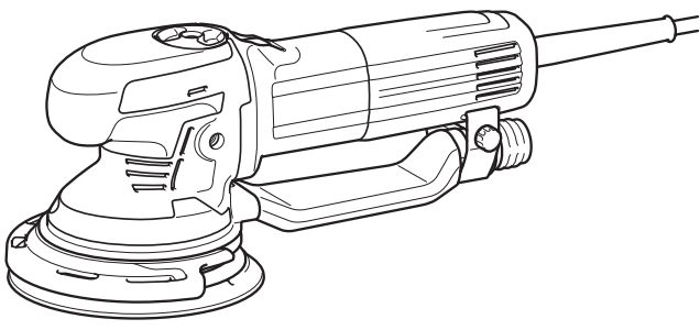
Makita BO6050 Random Orbit Sander Instruction Manual


Random Orbit Sander
INSTRUCTION MANUAL
BO6050


SPECIFICATIONS
| Model: | BO6050 |
| Pad diameter | 150 mm |
| Abrasive disc diameter | 150 mm |
| Orbits per minute (min-¹) | 1,600-6,800 |
| Overall length | 330 mm |
| Net weight | 2.6 kg |
| Safety class |
- Due to our continuing program of research and development, the specifications herein are subject to change without notice.
- Specifications may differ from country to country.
- Weight according to EPTA-Procedure 01/2003
Intended use
The tool is intended for the sanding of large surfaces of wood, plastic, and metal materials as well as painted surfaces.
Power supply
The tool should be connected only to a power supply of the same voltage as indicated on the nameplate, and can only be operated on a single-phase AC supply. They are double-insulated and can, therefore, also be used from sockets without earth wire.
Noise
The typical A-weighted noise level is determined according to EN60745:
Sound pressure level (LpA): 82 dB(A)
Sound power level (LWA): 93 dB (A)
Uncertainty (K): 3 dB(A)

Vibration
The vibration total value (tri-axial vector sum) determined according to EN60745:
Work mode: sanding metal plate
Vibration emission(ah): 5.0 m/s²
Uncertainty (K) : 1.5 m/s²
Work mode: polishing
Vibration emission (ah, AG) : 3.0 m/s²
Uncertainty (K) : 1.5 m/s²
NOTE: The declared vibration emission value has been measured in accordance with the standard test method and may be used for comparing one tool with another.
NOTE: The declared vibration emission value may also be used in a preliminary assessment of exposure.
EC Declaration of Conformity
For European countries only
Makita declares that the following Machine(s):
Designation of Machine: Random Orbit Sander
Model No./ Type: BO6050
Conforms to the following European Directives: 2006/42/EC
They are manufactured in accordance with the following standard or standardized documents: EN60745
The technical file in accordance with 2006/42/EC is available from:
Makita, Jan-Baptist Vinkstraat 2, 3070, Belgium
30.3.2015

Yasushi Fukaya
Director
Makita, Jan-Baptist Vinkstraat 2, 3070, Belgium
General power tool safety warnings
Save all warnings and instructions for future reference.
The term “power tool” in the warnings refers to your mains-operated (corded) power tool or battery-operated(cordless) power tool.
Sander safety warnings
- Always use safety glasses or goggles. Ordinary eyes or sunglasses are NOT safety glasses.
- Hold the tool firmly.
- Do not leave the tool running. Operate the tool only when hand-held.
- This tool has not been waterproofed, so do not use water on the workpiece surface.
- Ventilate your work area adequately when you perform sanding operations.
- Some material contains chemicals that may be toxic. Take caution to prevent dust inhalation and skin contact. Follow material supplier safety data.
- The use of this tool to sand some products, paints, and wood could expose users to dust containing hazardous substances. Use appropriate respiratory protection.
- Be sure that there are no cracks or breakage on the pad before use. Cracks or breakage may cause a personal injury.
SAVE THESE INSTRUCTIONS.
FUNCTIONAL DESCRIPTION
Switch action
To start the tool, slide the slide switch toward the “I (ON)” position. For continuous operation, press the front of the slide switch to lock it.
►Fig.1: 1. Slide switch
To stop the tool, press the rear of the slide switch, then slide it toward the “O (OFF)” position.
►Fig.2: 1. Slide switch
Speed adjusting dial
►Fig.3: 1. Speed adjusting dial
The rotating speed can be changed by turning the speed and adjusting dial to a given number setting from 1 to 5. Higher speed is obtained when the dial is turned in the direction of number 5. And lower speed is obtained when it is turned in the direction of number 1.
Refer to the table for the relationship between the number settings on the dial and the approximate rotating speed.
| Number | Orbits per min. | Pad rotating speed per minute in random orbit with forced rotation mode |
| 1 | 1,600 | 140 |
| 2 | 2,900 | 260 |
| 3 | 4,200 | 370 |
| 4 | 5,500 | 490 |
| 5 | 6,800 | 600 |
NOTICE: If the tool is operated continuously at low speeds for a long time, the motor will get overloaded, resulting in tool malfunction.
NOTICE: The speed adjusting dial can be turned only as far as 5 and back to 1. Do not force it past 5 or 1, or the speed adjusting function may no longer work.
Electronic function
The tools equipped with electronic functions are easy to operate because of the following features.
Constant speed control
Possible to get a fine finish, because the rotating speed is kept constant even under the loaded condition.
Soft start feature
Soft start because of suppressed starting shock.
Selecting the action mode
Use the change knob to change the rotation mode.
NOTICE: Always turn the knob fully. If the knob is in the middle position, you can not turn on the tool.
NOTE: You can not change the active mode when the tool is switched on.
Random orbit with forced rotation mode
►Fig.4: 1. Change knob
Random orbit with forced rotation mode is orbital action with forced rotation of the pad for rough sanding and polishing.
Rotate the change knob counterclockwise for random orbit with forced rotation mode.
Random orbit mode
►Fig.5: 1. Change knob
Random orbit mode is orbital action with free rotation of the pad for fine sanding.
Rotate the change knob clockwise for random orbit mode.
Typical applications for sanding and polishing
Sanding
| Material | Use | Mode selection | Speed control | Pad | |
| Random orbit with
forced rotation |
Random | ||||
| Paintwork | Sanding | – | 1 – 3 | Soft | |
| Repairs (scratches, rust spots) | 2 – 3 | Hard | |||
| Rough paint stripping | – | 4 – 5 | Soft | ||
| Plastics | Soft plastics (PVC/ ABS) | 1 – 3 | Super soft/Soft | ||
| Hard plastics (FRP) | – | 1 – 3 | Soft/Hard | ||
| Woods | Softwood | – | 1 – 3 | Super soft/Soft | |
| Hardwood | 3 – 5 | Soft | |||
| Veneers | – | 1 – 2 | Super Soft | ||
| Metals | Non-ferrous metal (aluminum, copper) | 1 – 3 | Soft | ||
| Steel | – | 3 – 5 | Soft/Hard | ||
| Steel, rust removal | – | 4 – 5 | Super Soft | ||
| Hard metal (stainless steel) | – | 4 – 5 | Soft | ||

Polishing
| Use | Mode selection | Speed control setting | Pad |
| Applying wax | Random orbit with forced rotation | 2 – 4 | Sponge pad |
| Removing wax | Random orbit with forced rotation | 4 – 5 | Felt pad |
| Polishing | Random orbit with forced rotation | 4 – 5 | Wool pad |
The above information is intended only as a guide. In each case, the most appropriate sanding disc grain should be determined by preliminary trials.
Protector
►Fig.6: 1. Protector
The protector prevents the pad, the tool housing and the wall from being damaged when working near a wall. Always use the protector when working.
To install the protector, align the tongue of the protector with the groove, and push in the protector.
To remove the protector, pull the protector forward.
►Fig.7: 1. Protector 2. Groove
ASSEMBLY
Installing side grip
►Fig.8: 1. Side grip
Screw the side grip on the tool securely.
The side grip can be installed on either side of the tool.
Installing or removing abrasive disc
►Fig.9: 1. Abrasive disc
To install the abrasive disc or the hook-and-loop type pad (optional accessory), first, remove all dirt and foreign matter from the pad.
Then attach the abrasive disc to the pad, using the hook-and-loop system of the abrasive disc and the pad.
Be careful to align the holes in the abrasive disc with those in the pad.
To remove the disc from the pad, just pull it up from its edge.
Changing pad
►Fig.10: 1. Random orbit with forced rotation mode 2. Shaft lock button 3. Pad
Makita offers an extensive range of optional super soft, soft, and hard pads.
To change the pad, perform as follows:
- Use the change knob and change the mode into random orbit with forced rotation mode.
- Press and hold the shaft lock button, and remove the pad by turning the pad counterclockwise.
- Keep holding the shaft lock button, and install a new pad by turning the pad clockwise firmly.
Dust nozzle
NOTICE: Do not carry the tool by the dust nozzle. Otherwise, the tool may be damaged.
You can remove the dust nozzle in accordance with the operation.
To remove the dust nozzle, loosen the bolt, slightly open the holder part, and remove the dust nozzle.
To install the dust nozzle, insert the mouth of the dust nozzle into the dust outlet of the housing, align the tongue of the holder part with the groove of the housing, and tighten the bolt.
►Fig.11: 1. Dust nozzle 2. Dust outlet 3. Mouth
►Fig.12: 1. Holder part 2. Bolt
Dust collection (optional accessory)
►Fig.13: 1. Front cuffs 24 2. Hose 3. Dust outlet
If a Makita hose is used, you can connect the front cuffs 24 to the dust outlet directly.
OPERATION
NOTICE: Be careful not to press down the shaft lock button. It may shorten tool life.
NOTICE: Never force the tool. Excessive pressure may decrease the sanding/polishing efficiency, damage the abrasive disc/pad or shorten tool life.
Sanding operation
NOTICE: Never run the tool without the abrasive disc. You may seriously damage the pad.
►Fig.14
Hold the tool firmly. Turn the tool on and wait until it attains full speed. Then gently place the tool on the workpiece surface. Keep the pad flush with the workpiece and apply slight pressure on the tool.
Polishing operation
Optional accessory
NOTICE: Continuous operation at high speed
may damage the work surface.
►Fig.15
- Applying wax
Use the sponge pad. Apply wax to the sponge pad or work surface. Run the tool at low speed to smooth out the wax.
NOTE: First, wax a not conspicuous portion of the work surface to make sure that the tool will not scratch the surface or result in uneven waxing. - Removing wax
Use the felt pad. Run the tool to remove the wax. - Polishing
Apply the wool pad gently to the work surface.
MAINTENANCE
CAUTION: Always be sure that the tool is switched off and unplugged before attempting to perform inspection or maintenance.
NOTICE: Never use gasoline, benzene, thinner, alcohol, or the like. Discoloration, deformation, or cracks may result.
To maintain product SAFETY and RELIABILITY, repairs, and any other maintenance or adjustment should be performed by Makita Authorized or Factory Service Centers, always using Makita replacement parts.
OPTIONAL ACCESSORIES
CAUTION: These accessories or attachments are recommended for use with your Makita tool specified in this manual. The use of any other accessories or attachments might present a risk of injury to persons. Only use accessory or attachment for its stated purpose.
If you need any assistance with more details regarding these accessories, ask your local Makita Service Center.
- Hook-and-loop type abrasive discs (with pre-punched holes)
- Hook-and-loop type sponge pad
- Hook-and-loop type felt pad
- Hook-and-loop type wool pad
- Pad 150 (Super soft, Soft, Hard)
- Pad 130 (Polishing)
- Side grip
NOTE: Some items in the list may be included in the tool package as standard accessories. They may differ from country to country.
Makita Jan-Baptist Vinkstraat 2, 3070, Belgium
Makita Corporation Anjo, Aichi, Japan
www.makita.com