Bosch GLL 3-80 C Multi Line Laser Range Instruction Manual
BOSCH GLL 3-80 C Multi Line Laser Range Instruction Manual

Product Overview

Safety Notes

- Caution – The use of other operating or adjusting equipment or the application of other processing methods than those mentioned here can lead to dangerous radiation exposure.
- The measuring tool is provided with a warning label (marked with number 20 in the representation of the measuring tool on the graphics page).
GLL 3-80 C
GLL 3-80 CG - If the text of the warning label is not in your national language, stick the provided warning label in your national language over it before operating for the first time.
Do not direct the laser beam at persons or animals and do not stare into the direct or reflected laser beam yourself, not even from a distance. You could blind somebody, cause accidents or damage your eyes. - If laser radiation strikes your eye, you must deliberately close your eyes and immediately turn your head away from the beam.
- Do not make any modifications to the laser equipment.
- Do not use the laser viewing glasses as safety goggles.
The laser viewing glasses are used for improved visualisation of the laser beam, but they do not protect against laser radiation. - Do not use the laser viewing glasses as sun glasses or in traffic. The laser viewing glasses do not afford complete UV protection and reduce colour perception.
- Have the measuring tool repaired only through qualified specialists using original spare parts. This ensures that the safety of the measuring tool is maintained.
- Do not allow children to use the laser measuring tool without supervision. They could unintentionally blind other persons or themselves.
- Do not operate the measuring tool in explosive environments, such as in the presence of flammable liquids, gases or dusts. Sparks can be created in the measuring tool which may ignite the dust or fumes.
- Loud audio signals will sound under certain conditions while operating the measuring tool. Therefore, keep the measuring tool away from your ear or other persons. The loud audio signal can cause hearing damage.
- Keep the measuring tool, the laser target plate 27 and the universal holder 24 away from magnetic data carriers and magnetically sensitive devices. The effect of the magnets inside the measuring tool, the laser target plate and the universal holder can lead to irreversible data loss.
- Please note that the measuring tool is operated using a button cell. Never swallow button cells. Swallowing button cells can result in severe internal burns within two hours and can cause death.
- Do not use the measuring tool if the button cell holder 22 does not close. Remove the button cell and have it repaired.
- Ensure that battery replacement is carried out properly. There is a risk of explosion.
- Do not attempt to recharge the button cells and do not short circuit the button cell. The button cell may leak, explode, catch fire and cause personal injury.
- Remove and dispose of drained batteries correctly.
Drained batteries may leak and damage the measuring tool or cause personal injury. - Do not overheat the batteries or throw them into fire.
The button cell may leak, explode, catch fire and cause personal injury. - Do not damage the button cell and or take the button cell apart. The button cell may leak, explode, catch fire and cause personal injury.
- Do not allow damaged button cells to come into contact with water. Leaking lithium may mix with water to create hydrogen, which could cause a fire, an explosion, or personal injury.
- Before any work on the measuring tool itself (e.g. assembling, maintenance, etc.) as well as when transporting and storing, remove the battery pack or the batteries from the measuring tool. Danger of injury when accidentally actuating the On/Off switch.
- Do not open the battery pack. Danger of short-circuiting.
Protect the battery pack against heat, e.g., against continuous intense sunlight, fire, water, and moisture. Danger of explosion. - When battery pack is not in use, keep it away from other metal objects like paper clips, coins, keys, nails, screws, or other small metal objects that can make a connection from one terminal to another. Shorting the battery terminals together may cause burns or a fire.
- Under abusive conditions, liquid may be ejected from the battery pack; avoid contact. If contact accidentally occurs, flush with water. If liquid contacts eyes, additionally seek medical help. Liquid ejected from the battery pack may cause irritations or burns.
- In case of damage and improper use of the battery pack, vapours may be emitted. Provide for fresh air and seek medical help in case of complaints. The vapours can irritate the respiratory system.
- Recharge only with the charger specified by the manufacturer. A charger that is suitable for one type of battery pack may create a risk of fire when used with another battery pack.
- Use the battery pack only in conjunction with your Bosch product. This measure alone protects the battery pack against dangerous overload.
- The battery pack can be damaged by pointed objects such as nails or screwdrivers or by force applied externally. An internal short circuit can occur and the battery pack can burn, smoke, explode or overheat.
- Caution! When using the measuring tool with Bluetooth®, interference with other devices and systems, airplanes and medical devices (e.g., cardiac pacemakers, hearing aids) may occur. Also, the possibility of humans and animals in direct vicinity being harmed cannot be completely excluded. Do not use the measuring tool with Bluetooth® in the vicinity of medical devices, petrol stations, chemical plants, areas where there is danger of explosion, and areas subject to blasting. Do not use the measuring tool with Bluetooth® in airplanes. Avoid operation in direct vicinity of the body over longer periods.


Product Description and Specifications
Please unfold the fold-out page with the representation of the measuring tool and leave it unfolded while reading the operating instructions.
The Bluetooth® word mark and logos are registered trademarks owned by Bluetooth SIG, Inc. and any use of such marks by Robert Bosch Power Tools GmbH is under licence.
Intended Use
The measuring tool is intended for determining and checking
horizontal and vertical lines.
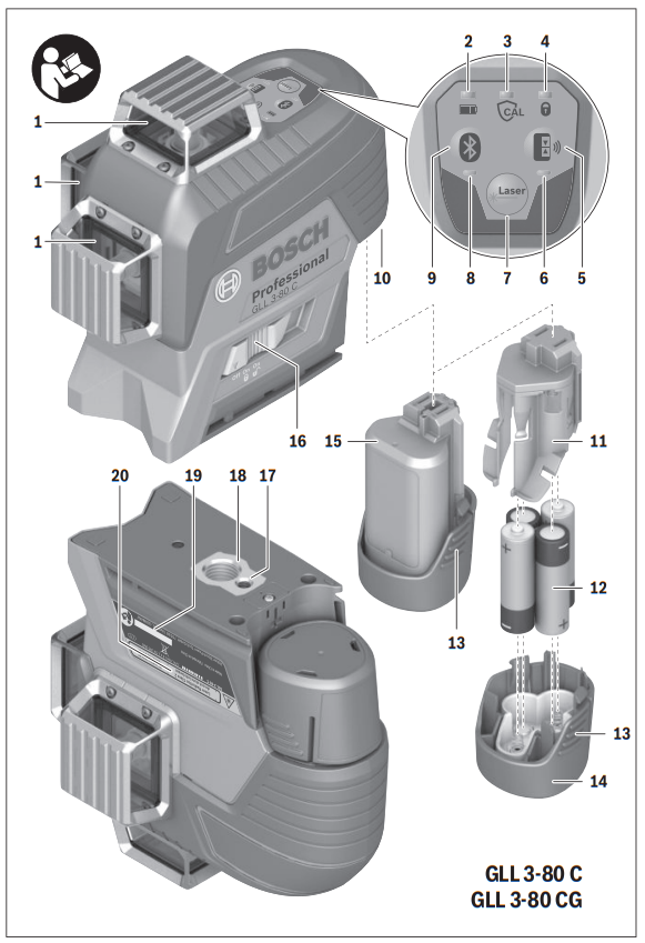
Product Features
The numbering of the product features shown refers to the illustration of the measuring tool on the graphic page.
- Exit opening for laser beam
- Charging condition of battery pack/batteries
- CAL guard indicator
- Working without automatic levelling indicator
- Receiver mode button
- Receiver mode indicator
- Button for laser operating mode
- Indicator for Bluetooth® connection
- Bluetooth® button
- Battery port
- Battery adapter cover*
- Batteries*
- Release button for battery pack/battery adapter*
- Battery adapter sealing cap*
- Battery pack*
- On/Off switch
- Tripod mount 1/4″
- Tripod mount 5/8″
- Serial number
- Laser warning label
- Button cell
- Button cell holder
- Button cell port
- Universal holder*
- Rotating platform*
- Laser receiver*
- Laser target plate*
- Laser viewing glasses*
- Protective pouch*
- Tripod*
- Telescopic rod*
- Case*
- Inlay*

* The accessories illustrated or described are not included as standard delivery.
Technical Data
| Line laser | GLL 3-80 C | GLL 3-80 CG |
| Article number | 3 601 K63 R. | 3 601 K63 T.. |
Working range1)
|
30 m 25 m 5–120 m |
30 m 25 m 5–120 m |
| Levelling Accuracy, typically | ±0.2 mm/m | ±0.2 mm/m |
| Self-levelling range, typically | ±4° | ±4° |
| Levelling duration, typically | <4s | <4s |
| Relative air humidity, max. | 90 % | 90 % |
| Laser class | 2 | 2 |
| Laser type | 630–650 nm, | 500–540 nm, |
| C6 | 10 | 10 |
| Divergence of laser line | 50 x 10 mrad (full angle) | 50 x 10 mrad (full angle) |
| Shortest pulse duration | 1/10000 s | 1/10000 s |
| Compatible laser receivers | LR6, LR7 | LR7 |
| Tripod mount | 1/4″, 5/8″ | 1/4″, 5/8″ |
Measuring tool power supply
|
10.8 V/12 V 4 x 1.5 V LR6 (AA) (with battery adapter) |
10.8 V/12 V 4 x 1.5 V LR6 (AA) (with battery adapter) |
Operating time with 3 laser levels2)
|
8 h 6 h |
6 h 4 h |
Bluetooth® measuring tool
|
Bluetooth® 4.0 (Low Energy)3) 30 m4) 2402 –2480 MHz |
Bluetooth® 4.0 (Low Energy)3) 30 m4) 2402 –2480 MHz |
Bluetooth® smartphone
|
Bluetooth® 4.0 (Low Energy)3) Android 4.3 (and above) iOS 7 (and above |
Bluetooth® 4.0 (Low Energy)3) Android 4.3 (and above) iOS 7 (and above) |
Weight according to EPTA-Procedure 01:2014
|
0.90 kg 0.86 kg |
0.90 kg 0.86 kg |
| Dimensions (length x width x height) | 162 x 84 x 148 mm | 162 x 84 x 148 mm |
| Degree of protection | IP 54 (dust and splash water protected) | IP 54 (dust and splash water protected) |
Permitted ambient temperature
|
0 °C…+45 °C –10 °C…+40 °C –20 °C…+70 °C |
0 °C…+45 °C –10 °C…+40 °C –20 °C…+70 °C |
| ||
| Recommended batteries | GBA 10,8V … GBA 12V … except for GBA 12V 4,0 Ah |
GBA 10,8V … GBA 12V … except for GBA 12V 4,0 Ah |
| Recommended chargers | AL 11.. CV GAL 12.. CV |
AL 11.. CV GAL 12.. CV |
| ||
Assembly
Measuring tool power supply
The measuring tool can either be operated with commercially available batteries or with a Bosch lithium-ion battery pack.
Operation with Battery Pack
Note: Use of battery packs not suitable for the measuring tool can lead to malfunctions of or cause damage to the measuring tool.
Note: The battery pack is supplied partially charged. To ensure full capacity of the battery pack, completely charge the battery pack in the battery charger before using for the first time.
- Use only the chargers listed in the technical data. Only these battery chargers are matched to the lithium-ion battery of your measuring tool.
The lithium-ion battery pack can be charged at any time without reducing its service life. Interrupting the charging procedure does not damage the battery pack.
The “Electronic Cell Protection (ECP)” protects the lithiumion battery pack against deep discharging. When the battery pack is discharged, the measuring tool is switched off by a protective circuit.
- Do not switch the measuring tool back on after it has been switched off by the protective circuit. The battery pack can be damaged.
To insert the charged battery pack 15, slide it into the battery port until you feel it engage.
To remove the battery pack 15, press the unlocking buttons 13 and pull the battery pack out of the battery port 10. Do not use force to do this.
Operation with Batteries
Alkali-manganese batteries are recommended for the measuring tool.
The batteries are inserted into the battery adapter.
- The non-rechargeable battery adapter is intended only for use in designated Bosch measuring tools and must not be used with power tools.
To insert the batteries, slide the cover 11 of the battery adapter into the battery port 10. Place the batteries in the cover as shown in the illustration on the sealing cap 14. Slide the sealing cap over the cover until you feel it click into place.
To remove the inside cover 11 from the battery port 10, reach into the cover and pull it out of the measuring tool by applying light pressure to the side wall.

Always replace all batteries at the same time. Only use batteries from one brand and with the identical capacity.
- Remove the batteries from the measuring tool when not using it for extended periods. When storing for extended periods, the batteries can corrode and self-discharge.
Battery Status Indicator
The battery status indicator 2 shows the charge condition of the battery pack or batteries:
| LED | Charge Condition |
| Continuous lighting, green | 100–75 % |
| Continuous lighting, yellow | 75–35 % |
| Continuous lighting, red | 35–10 % |
| No light |
|
If the battery pack or the batteries are running low, the laser lines will gradually become dimmer.
Immediately replace a fault battery pack or empty batteries.
Operation
Initial Operation
- Protect the measuring tool against moisture and direct sun light.
- Do not subject the measuring tool to extreme temperatures or variations in temperature. As an example, do not leave it in vehicles for a long time. In case of large variations in temperature, allow the measuring tool to adjust to the ambient temperature before putting it into operation.
In case of extreme temperatures or variations in temperature, the accuracy of the measuring tool can be impaired. - Avoid heavy impact to or falling down of the measuring tool. After severe exterior effects to the measuring tool, it is recommended to carry out an accuracy check (see “Accuracy Check of the Measuring Tool”, page 21) each time before continuing to work.
- Switch the measuring tool off during transport. When switching off, the levelling unit is locked. Else it can be damaged in case of intense movement.
Switching On and Off
To switch on the measuring tool, slide the On/Off switch 16 to the “


- Do not point the laser beam at persons or animals and do not look into the laser beam yourself, not even from a large distance.
To switch off the measuring tool, slide the On/Off switch 16 to the “Off” position. When switching off, the levelling unit is locked.
- Do not leave the switched-on measuring tool unattended and switch the measuring tool off after use. Other persons could be blinded by the laser beam.
When exceeding the maximum permitted operating temperature of 40 °C, the measuring tool switches off to protect the laser diode. After cooling down, the measuring tool is ready for operation and can be switched on again.
If the temperature of the measuring tool is approaching the maximum permissible operating temperature, the laser lines will gradually become dimmer.
Deactivating the Automatic Shut-off
When no button on the measuring tool is pressed for approx. 120 minutes, the measuring tool automatically switches off to save the batteries.
To switch the measuring tool back on after automatic shut-off, you can either slide the On/Off switch 16 to the “Off” position first and then switch the measuring tool back on, or press either the laser mode button 7 or the receiver mode button 5 once.
To deactivate the automatic shut-off function, hold down the laser mode button 7 for at least 3 s (with the measuring tool switched on). If the automatic shut-off function is deactivated, the laser beams will flash briefly as confirmation.
To activate the automatic shut-off, switch the measuring tool off and then on again.
Deactivating the Signal Tone
After the measuring tool has been switched on, the audio signal is always activated.
To deactivate or activate the audio signal, simultaneously press the laser mode button 7 and the receiver mode button 5 and hold them down for at least 3 s.
The audio signal activation and deactivation are both confirmed by three short beeps.
Operating Modes
The measuring tool has several operating modes between which you can switch at any time. These are for:
- Generating a horizontal laser plane,
- Generating a vertical laser plane,
- Generating two vertical laser planes,
- Generating a horizontal laser plane as well as two vertical laser planes.
After you switch it on, the measuring tool generates a horizontal laser plane. To change the operating mode, press the laser mode button 7.
All operating modes can be selected both with and without automatic levelling.
Receiver mode
Receiver mode must be activated to work with the laser receiver 26 – regardless of which operating mode is selected.
In receiver mode the laser lines flash at very high frequency, enabling them to be detected by the laser receiver 26.
To switch on receiver mode, press button 5. Indicator 6 will light up green.
When receiver mode is switched on, the laser lines are less visible to the human eye. For this reason, switch receiver mode off by pressing button 5 again to work without a laser receiver. Indicator 6 will extinguish.
Automatic Levelling
Working with Automatic Levelling
Position the measuring tool on a level and firm support, attach it to the holder 24 or to the tripod 30.
When working with automatic levelling, push the On/Off switch 16 to the “

After switching on, the levelling function automatically compensates irregularities within the self-levelling range of ±4°.
The levelling is finished as soon as the laser beams do not move any more.
If automatic levelling is not possible, e.g. because the surface on which the measuring tool stands deviates by more than 4° from the horizontal plane, the laser lines begin to flash rapidly.
When the audio signal is activated, a fast-beat signal sounds.
Set up the measuring tool in level position and wait for the self-levelling to take place. As soon as the measuring tool is within the self-levelling range of ±4°, all laser beams light up continuously and the audio signal is switched off.
In case of ground vibrations or position changes during operation, the measuring tool is automatically levelled in again. To avoid errors, check the position of the horizontal and vertical laser line with regard to the reference points upon re-levelling.
Working without Automatic Levelling
For work without automatic levelling, slide the on/off switch 16 to the “

When automatic levelling is switched off, you can hold the measuring tool freely in your hand or place it on an inclined surface. The laser lines no longer necessarily run perpendicular to each other.
Remote control via the “Levelling Remote App”
The measuring tool is equipped with a Bluetooth® module which uses radio technology to enable remote control via a smartphone with a Bluetooth® interface.
The “Levelling Remote App” application (app) is needed to use this function. You can download this in the app store for your terminal device (Apple App Store, Google Play Store).
For information on the necessary system requirements for a
Bluetooth® connection, please refer to the Bosch website at www.bosch-pt.com
When remote controlling by means of Bluetooth®, time lags may occur between mobile terminal/device and measuring tool as a result of poor reception conditions.
Switching On Bluetooth®
To switch on Bluetooth® for the remote control, press the Bluetooth®-button 9. Ensure that the Bluetooth® interface is activated on your mobile terminal/device.
After starting the Bosch application, the connection between the mobile terminal/device and the measuring tool is established. When several active measuring tools are found, select the appropriate measuring tool. When only one active measuring tool is found, the connection is automatically established.
The connection is established as soon as the Bluetooth® indicator 8 lights up.
The Bluetooth® connection may be interrupted if there is too much distance or there are obstacles between measuring tool and mobile terminal/device and if there are any electromagnetic interference sources. In this case, the Bluetooth® indicator flashes.
Switching Off Bluetooth®
To switch off Bluetooth® for the remote control, press the Bluetooth®-button 9 or switch off the measuring tool.
CAL guard calibration warning
The CAL guard calibration warning sensors monitor the status of the measuring tool, even when it is switched off. If the measuring tool is not being supplied with power by a battery pack or batteries, an internal energy storage battery provides continuous monitoring by the sensors for 72 hours.
The sensors are activated when the measuring tool is started up for the first time.
Calibration warning triggers
If one of the following events occurs, the CAL guard calibration warning is triggered and the indicator 3 lights up red:
- The calibration interval (every 12 months) has expired.
- The measuring tool was stored outside of the storage temperature range.
- The measuring tool suffered a severe shock (e.g. impact on the floor after a fall).
You can refer to the “Levelling Remote App” to see which of the three events triggered the calibration warning. Without the app, the cause cannot be identified as the CAL guard indicator, the CAL guard indicator 3 lighting up indicates merely that the levelling accuracy needs to be checked.
Once the warning has been triggered, the CAL guard indicator 3 lights up until the levelling accuracy has been checked and the indicator switched off.
Procedure in the event of a calibration warning being triggered
Check the levelling accuracy of the measuring tool (see “Accuracy Check of the Measuring Tool”, page 21).
If the maximum deviation has not been exceeded in any of the tests, switch the CAL guard indicator 3 off. To do so, press and hold the receiver mode button 5 and the Bluetooth® button 9 at the same time for at least 3 s. The CAL guard indicator 3 goes out.
Should the measuring tool exceed the maximum deviation during one of the tests, please have it repaired by a Bosch after-sales service.
Accuracy Check of the Measuring Tool
Influences on Accuracy
The ambient temperature has the greatest influence. Especially temperature differences occurring from the ground upward can divert the laser beam.
Because the largest difference in temperature layers is close to the ground, the measuring tool should always be mounted on a tripod when measuring distances exceeding 20 m. If possible, also set up the measuring tool in the centre of the work area.
In addition to external influences, device-specific influences (e.g. falls or heavy impacts) can also lead to deviations. For this reason, check the levelling accuracy each time before beginning work.
Firstly, check the levelling accuracy of the horizontal laser line and then the levelling accuracy of the vertical laser lines.
Should the measuring tool exceed the maximum deviation during one of the tests, please have it repaired by a Bosch after-sales service.
Checking the Horizontal Levelling Accuracy of the Lateral Axis
For this check, a free measuring distance of 5 m on a firm surface between two walls A and B is required.
- Mount the measuring tool onto a tripod, or place it on a firm and level surface close to wall A. Switch on the measuring tool to operation with automatic levelling. Select the operating mode in which a horizontal laser plane as well as a vertical laser plane in front of the measuring tool are generated.
- Direct the laser against the close wall A and allow the measuring tool to level in. Mark the centre of the point where the laser lines cross each other at wall A (point I).
- Turn the measuring tool by 180°, allow it to level in and mark the cross point of the laser lines on the opposite wall B (point II).
- Without turning the measuring tool, position it close to wall B. Switch the measuring tool on and allow it to level in.
- Align the height of the measuring tool (using a tripod or by underlaying, if required) in such a manner that the cross point of the laser lines is projected against the previously marked point II on the wall B.
- Without changing the height, turn around the measuring tool by 180°. Direct it against the wall A in such a manner that the vertical laser line runs through the already marked point I. Allow the measuring tool to level in and mark the cross point of the laser lines on the wall A (point III).
- The difference d of both marked points I and III on wall A results in the actual height deviation of the measuring tool alongside the lateral axis.


On the measuring distance of 2 x 5 m = 10 m, the maximum allowable deviation is: 10 m x ±0.2 mm/m = ±2 mm.
Thus, the difference d between points I and III must not exceed 2 mm (max.).
Checking the Levelling Accuracy of the Vertical Lines
For this check, a door opening is required with at least 2.5 m of space (on a firm surface) to each side of the door.
- Position the measuring tool on a firm, level surface (not on a tripod) 2.5 m away from the door opening. Switch on the measuring tool to operation with automatic levelling. Select an operating mode in which a vertical laser plane is generated in front of the measuring tool.
- Mark the centre of the vertical laser line at the floor of the door opening (point I), at a distance of 5 m beyond the other side of the door opening (point II) and at the upper edge of the door opening (point III).
- Rotate the measuring tool by 180° and position it on the other side of the door opening directly behind point II. Allow the measuring tool to level in and align the vertical laser line in such a manner that its centre runs exactly through points I and II.
- Mark the centre of the laser line at the upper edge of the door opening as point IV.
- The difference d of both marked points III and IV results in the actual deviation of the measuring tool to the plumb line.
- Measure the height of the door opening.


Repeat the measuring procedure for the second vertical laser plane. For this, select an operating mode in which a vertical laser plane is generated aside of the measuring tool, and turn the measuring tool by 90° before beginning with the measuring procedure.
The maximum admissible deviation is calculated as follows:
Doubled height of the door opening x 0.2 mm/m
Example: For a door-opening height of 2 m, the maximum deviation may be 2 x 2 m x ±0.2 mm/m = ±0.8 mm. Consequently, points III and IV may be no more than 0.8 mm (max.) apart from each other for each of both measurements.
Working Advice
- Always use the centre of the laser line for marking. The width of the laser line changes with the distance.
- The measuring tool is equipped with a radio interface.
Local operating restrictions, e.g. in airplanes or hospitals, are to be observed.
Working with the Laser Target Plate
The laser target plate 27 increases the visibility of the laser beam under unfavourable conditions and at large distances.
The reflective part of the laser target plate 27 improves the visibility of the laser line. Thanks to the transparent part, the laser line is also visible from the back side of the laser target plate.
Working with the Tripod (Accessory)
A tripod offers a stable, height-adjustable measuring support.
Position the measuring tool with the 1/4″ tripod mount 17 onto the thread of the tripod 30 or a commercially available camera tripod. For fastening to a commercially available construction tripod, use the 5/8″ tripod mount 18. Tighten the measuring tool with the tripod mounting stud.
Adjust the tripod roughly before switching on the measuring tool.
Fastening with the Universal Holder (Accessory) (see figure B)

With the universal holder 24, you can fasten the measuring tool, e.g., to vertical surfaces, pipes or magnetisable materials. The universal holder is also suitable for use as a ground tripod and makes the height adjustment of the measuring tool easier.
Adjust the universal holder roughly before 24 switching on the measuring tool.
Working with the Laser Receiver (Accessory) (see figure B)
Use the laser receiver 26 to improve detection of the laser lines in adverse lighting conditions (bright environment, direct sunlight) and over greater distances. Switch on receiver mode when working with the laser receiver (see “Receiver mode”, page 20).
Laser Viewing Glasses (Accessory)
The laser viewing glasses filter out ambient light. This enhances the laser visibility for the eye.
- Do not use the laser viewing glasses as safety goggles.
The laser viewing glasses are used for improved visualisation of the laser beam, but they do not protect against laser radiation. - Do not use the laser viewing glasses as sun glasses or in traffic. The laser viewing glasses do not afford complete UV protection and reduce colour perception.
Work Examples (see figures A–F)


Applicational examples for the measuring tool can be found on the graphics pages.
Always position the measuring tool close to the surface or edge you want to check, and allow it to level in prior to each measurement.
Maintenance and Service
Maintenance and Cleaning
Store and transport the measuring tool only in the protective pouch or in the case.
Keep the measuring tool clean at all times.
Do not immerse the measuring tool in water or other fluids.
Wipe off debris using a moist and soft cloth. Do not use any cleaning agents or solvents.
Regularly clean the surfaces at the exit opening of the laser in particular, and pay attention to any fluff or fibres.
In case of repairs, send in the measuring tool packed in its protective pouch 29.
After-sales Service and Application Service
Our after-sales service responds to your questions concerning maintenance and repair of your product as well as spare parts. Exploded views and information on spare parts can also be found under:
www.bosch-pt.com
Bosch’s application service team will gladly answer questions concerning our products and their accessories.
In all correspondence and spare parts orders, please always include the 10-digit article number given on the nameplate of the product.
Great Britain
Robert Bosch Ltd. (B.S.C.)
P.O. Box 98
Broadwater Park
North Orbital Road
Denham
Uxbridge
UB 9 5HJ
At www.bosch-pt.co.uk you can order spare parts or arrange
the collection of a product in need of servicing or repair.
Tel. Service: (0344) 7360109
E-Mail: [email protected]
Ireland
Origo Ltd.
Unit 23 Magna Drive
Magna Business Park
City West
Dublin 24
Tel. Service: (01) 4666700
Fax: (01) 4666888
Australia, New Zealand and Pacific Islands
Robert Bosch Australia Pty. Ltd.
Power Tools
Locked Bag 66
Clayton South VIC 3169
Customer Contact Center
Inside Australia:
Phone: (01300) 307044
Fax: (01300) 307045
Inside New Zealand:
Phone: (0800) 543353
Fax: (0800) 428570
Outside AU and NZ:
Phone: +61 3 95415555
www.bosch-pt.com.au
www.bosch-pt.co.nz
Supplier code ERAC000385
Republic of South Africa
Customer service
Hotline: (011) 6519600
Gauteng – BSC Service Centre
35 Roper Street, New Centre
Johannesburg
Tel.: (011) 4939375
Fax: (011) 4930126
E-Mail: [email protected]
KZN – BSC Service Centre
Unit E, Almar Centre
143 Crompton Street
Pinetown
Tel.: (031) 7012120
Fax: (031) 7012446
E-Mail: [email protected]
Western Cape – BSC Service Centre
Democracy Way, Prosperity Park
Milnerton
Tel.: (021) 5512577
Fax: (021) 5513223
E-Mail: [email protected]
Bosch Headquarters
Midrand, Gauteng
Tel.: (011) 6519600
Fax: (011) 6519880
E-Mail: [email protected]
Transport
The usable lithium-ion battery packs are subject to the Dangerous Goods Legislation requirements. The user can transport the battery packs by road without further requirements.
When being transported by third parties (e.g. via air transport or forwarding agency), special requirements on packaging and labelling must be observed. For preparation of the item being shipped, consulting an expert for hazardous material is required.
Dispatch battery packs only when the housing is undamaged. Tape or mask off open contacts and pack up the battery pack in such a manner that it cannot move around in the packaging.
Please also observe possibly more detailed national regulations.
Disposal


Only for EC countries:
According to the European Guideline 2012/19/EU, measuring tools that are no longer usable, and according to the European Guideline 2006/66/EC, defective or used battery packs/batteries, must be collected separately and disposed of in an environmentally correct manner.
Batteries no longer suitable for use can be directly returned at:
Great Britain
Robert Bosch Ltd. (B.S.C.)
P.O. Box 98
Broadwater Park
North Orbital Road
Denham
Uxbridge
UB 9 5HJ
At www.bosch-pt.co.uk you can order spare parts or arrange
the collection of a product in need of servicing or repair.
Tel. Service: (0344) 7360109
E-Mail: [email protected]
Battery packs/batteries:
Li-ion:
Please observe the instructions in section “Transport”, page 24.
Integrated batteries may only be removed for disposal by qualified personnel. Opening the housing shell can destroy the measuring tool.
Subject to change without notice.
Robert Bosch Power Tools GmbH hereby declares that the GLL3-80 C, GLL3-80 CG radio communication unit complies with Directive 2014/53/EU. The full EU declaration of conformity is available at the following website:
http://eu-doc.bosch.com/
