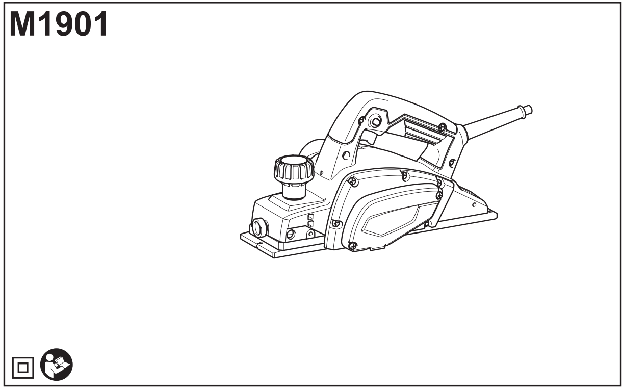
Makita M1901 240V Heavy Duty Corded Planer Instruction Manual


Planer
INSTRUCTION MANUAL


SPECIFICATIONS
| Model: | M1901 |
| Planing width | 82 mm |
| Planting depth | 2 mm |
| Shipping depth | 9 mm |
| No-load speed | 16,000 min.’ |
| Overall length | 285 mm |
| Net weight | 2.7 kg |
| Safety class |

- Due to our continuing program of research and development, the specifications herein are subject to change without notice.
- Specifications may differ from country to country.
- Weight according to EPTA-Procedure 01/2003
Intended use
The tool is intended for planning wood.
Power supply
The tool should be connected only to a power supply of the same voltage as indicated on the nameplate, and can only be operated on a single-phase AC supply. They are double-insulated and can, therefore, also be used from sockets without earth wire.
Noise
The typical A-weighted noise level is determined according to EN60745:
Sound pressure level (LpA) : 85 dB(A)
Sound power level (LWA) : 96 dB (A)
Uncertainty (K) : 3 dB(A)

Vibration
The vibration total value (tri-axial vector sum) determined according to EN60745: Work mode: planing softwood Vibration emission (ah) : 3.5 m/s² Uncertainty (K) : 1.5 m/s²
NOTE: The declared vibration emission value has been measured in accordance with the standard test method and may be used for comparing one tool with another.
NOTE: The declared vibration emission value may also be used in a preliminary assessment of exposure.
EC Declaration of Conformity
For European countries only
Makita declares that the following Machine(s):
Designation of Machine: Planer
Model No./ Type: M1901
Conforms to the following European Directives: 2006/42/EC
They are manufactured in accordance with the following
standard or standardized documents: EN60745
The technical file in accordance with 2006/42/EC is available from:
Makita, Jan-Baptist Vinkstraat 2, 3070, Belgium 17.8.2015

Makita, Jan-Baptist Vinkstraat 2, 3070, Belgium
General power tool safety warnings
Save all warnings and instructions for future reference.
The term “power tool” in the warnings refers to your mains-operated (corded) power tool or battery-operated(cordless) power tool.
Planer safety warnings
- Wait for the cutter to stop before setting the tool down. An exposed rotating cutter may engage the surface leading to possible loss of control and serious injury.
- Hold the power tool by insulated gripping surfaces only, because the cutter may contact its own cord. Cutting a “live” wire may make exposed metal parts of the power tool “live” and could give the operator an electric shock.
- Use clamps or another practical way to secure and support the workpiece to a stable platform. Holding the work by your hand or against the body leaves it unstable and may lead to loss of control.
- Rags, cloth, cord, string and the like should never be left around the work area.
- Avoid cutting nails. Inspect for and remove all nails from the workpiece before operation.
- Use only sharp blades. Handle the blades very carefully.
- Be sure the blade installation bolts are securely tightened before operation.
- Hold the tool firmly with both hands.
- Keep hands away from rotating parts.
- Before using the tool on an actual workpiece, let it run for a while. Watch for vibration or wobbling that could indicate poor installation or a poorly balanced blade.
- Make sure the blade is not contacting the workpiece before the switch is turned on.
- Wait until the blade attains full speed before cutting.
- Always switch off and wait for the blades to come to a complete stop before any adjusting.
- Never stick your finger into the chip chute. The chute may jam when cutting damp wood. Clean out chips with a stick.
- Do not leave the tool running. Operate the tool only when hand-held. 16. Always change both blades or covers on the drum, otherwise, the resulting imbalance will cause vibration and shorten tool life.
- Use only Makita blades specified in this manual.
- Always use the correct dust mask/respirator for the material and application you are working with.
SAVE THESE INSTRUCTIONS.
FUNCTIONAL DESCRIPTION
Adjusting the depth of cut
► Fig.1: 1. Pointer 2. Knob
The depth of cut may be adjusted by simply turning the knob on the front of the tool so that the pointer points the desired depth of cut.
Switch action
► Fig.2: 1. Switch trigger 2. Lock button or Lock-off button
For a tool with a lock button
To start the tool, simply pull the switch trigger. Release the switch trigger to stop. For continuous operation, pull the switch trigger and then push in the lock button. To stop the tool from the locked position, pull the switch trigger fully, then release it.
For a tool with a lock-off button
To prevent the switch trigger from being accidentally pulled, a lock-off button is provided. To start the tool, depress the lock-off button and pull the switch trigger. Release the switch trigger to stop.
Foot
► Fig.3: 1. Planer blade 2. Rear base 3. Foot
After a cutting operation, raise the back side of the tool so that the foot comes out of the rear base. This prevents the planer blades to be damaged.
ASSEMBLY
Removing or installing planer blades
For tool with conventional planer blades
To remove the planer blades on the drum, unscrew the installation bolts with the socket wrench. The drum cover comes off together with the blades.
► Fig.4: 1. Socket wrench 2. Bolts
► Fig.5: 1. Bolts 2. Drum 3. Planer blade 4. Drum cover 5. Adjusting plate 6. Groove
To install the planer blades, do the following procedure.
- Clean out all chips or foreign matter adhering to the drum and planer blades.
- Choose planer blades of the same dimensions and weight. Otherwise, drum oscillation/vibration will result, causing poor planning action and, eventually, tool breakdown.
- Use the blade gauge to set the planer blades correctly. Put the planer blade on the gauge base. Apply the cutting edge of the blade on the inside flank of the gauge plate.
► Fig.6: 1. Inside flank of gauge plate 2. Blade edge 3. Planer blade 4. Adjusting plate 5. Screws 6. Heel 7. Back side of gauge base 8. Gauge plate 9. Gauge base - Place the adjusting plate on the planer blade. Press the adjusting plate so that its heel is flush with the back side of the gauge base. Tighten two screws on the adjusting plate.
- Slip the heel of the adjusting plate into the drum groove, then fit the drum cover on it.
- Tighten all the installation bolts evenly and alternately with the socket wrench.
- Repeat the procedure above for the other blade.
For tool with mini planer blades
To replace the mini planer blades, do the following procedure.
- Carefully clean the drum surfaces and the drum cover.
- Unscrew the three installation bolts with the socket wrench. Remove the drum cover, adjusting plate, set plate, and the mini planer blade.
► Fig.7: 1. Socket wrench 2. Bolts - Use the blade gauge to set the planer blades correctly. Put the mini planer blade on the gauge base. Apply the cutting edge of the blade on the inside flank of the gauge plate.
► Fig.8: 1. Screws 2. Adjusting plate 3. Planer blade locating lugs 4. Gauge plate 5. The heel of adjusting plate 6. Set plate 7. Inside flank of gauge plate 8. Gauge base 9. The back side of gauge base 10. Mini planer blade - Loosely attach the adjusting plate to the set plate with the screws. Put the adjusting plate and set the plate on the gauge base. Fit the planer blade locating lugs on the set plate into the mini planer blade groove.
- Apply the heel of the adjusting plate onto the back side of the gauge base and tighten the screws. Check the alignments carefully to ensure uniform cutting.
- Slip the heel of the adjusting plate into the groove of the drum.
- Put the drum cover on the set plate and loosely fit them onto the drum with the three bolts. Slip the mini planer blade into the space between the drum and set plate. Make sure that the planer blade locating lugs on the set plate fit in the mini planer blade groove.
► Fig.9: 1. Mini planer blade 2. Groove 3. Set plate 4. Bolts 5. Drum cover 6. Drum 7. Adjusting plate - Adjust the mini planer blade position lengthways so that the blade ends are clear and equidistant from the housing on one side and the metal bracket on the other.
- Tighten the three bolts with the socket wrench provided and rotate the drum to check the clearances between the blade ends and the tool body.
- Check the three bolts for final tightness.
- Repeat the procedure above for the other blade.
For the correct planer blade setting
Your planing surface will end up rough and uneven unless the planer blade is set properly and securely. The planer blade must be mounted so that the cutting edge is absolutely level, that is, parallel to the surface of the rear base. Refer to some examples below for proper and improper settings.
(A) Front base (Movable shoe)
(B) Rear base (Stationary shoe)
Correct setting

Nicks in surface

Gouging at start

Gouging at end

Connecting a vacuum cleaner
For European countries only
► Fig.10
When you wish to perform a clean planning operation, connect a Makita vacuum cleaner to your tool. Then connect a hose of the vacuum cleaner to the nozzle as shown in the figures.
OPERATION
Hold the tool firmly with one hand on the knob and the other hand on the switch handle when performing the tool.
Planing operation
► Fig.11: 1. Start 2. End
Apply the tool front base flat upon the workpiece surface without the planer blades contacting the workpiece. Switch on and wait until the blades attain full speed. Then move the tool gently forward at a uniform speed. Apply pressure on the front of the tool at the start of planning, and on the rear at the end of planning. The speed and depth of the cut determine the finish. To obtain a good surface finish, plane deeply until you get near the desired depth, and then plane thinly and slowly for the final pass.
Shipping (Rabbeting)
► Fig.12
To make a stepped cut as shown in the figure, use the edge fence (guide rule). Draw a cutting line on the workpiece. Insert the edge fence into the hole in the front of the tool. Align the blade edge with the cutting line.
► Fig.13: 1. Blade edge 2. Cutting line
Adjust the edge fence until it comes in contact with the side of the workpiece, then secure it by tightening the screw.
► Fig.14: 1. Screw 2. Edge fence
When planning, move the tool with the edge fence flush with the side of the workpiece. Otherwise, uneven planning may result.
► Fig.15
The maximum shipping (rabbeting) depth is 9 mm (11/32″).
You may wish to add to the length of the fence by attaching an extra piece of wood. Convenient holes are provided in the fence for this purpose, and also for attaching an extension guide (optional accessory).
► Fig.16
NOTE: The shape of the guiding rule differs from country to country. In some countries, the guiding rule is not included as a standard accessory.
Chamfering
► Fig.17
► Fig.18
To make a chamfering cut as shown in the figure, align the “V” groove in the front base with the edge of the workpiece and plane it.
MAINTENANCE
Sharpening the planer blades
For conventional planer blades only
Always keep your planer blades sharp for the best performance possible. Use the sharpening holder (optional accessory) to remove nicks and produce a fine edge.
► Fig.19: 1. Sharpening holder
First, loosen the two wing nuts on the holder and insert the planer blades (A) and (B), so that they contact the sides (C) and (D). Then tighten the wing nuts.
► Fig.20: 1. Wing nut 2. Planer blade (A) 3. Planer blade (B) 4. Side (D) 5. Side (C)
Immerse the dressing stone in water for 2 or 3 minutes before sharpening. Hold the holder so that both blades contact the dressing stone for simultaneous sharpening at the same angle.
► Fig.21
Replacing carbon brushes
► Fig.22: 1. Limit mark
Remove and check the carbon brushes regularly. Replace when they wear down to the limit mark. Keep the carbon brushes clean and free to slip in the holders. Both carbon brushes should be replaced at the same time. Use only identical carbon brushes. Use a screwdriver to remove the chip cover or nozzle.
► Fig.23: 1. Chip cover or Nozzle 2. Screwdriver
Use a screwdriver to remove the brush holder caps. Take out the worn carbon brushes, insert the new ones, and secure the brush holder caps.
► Fig.24: 1. Brush holder cap 2. Screwdriver
To maintain product SAFETY and RELIABILITY, repairs, and any other maintenance or adjustment should be performed by Makita Authorized or Factory Service Centers, always using Makita replacement parts.
Makita Jan-Baptist Vinkstraat 2, 3070, Belgium
Makita Corporation Anjo, Aichi, Japan
www.makita.com
885473-979
EN, PL, HU, SK,
CS, UK, RO, DE
20150930