Makita DHR400 Cordless Rotary Hammer Instruction Manual

Instruction Manual

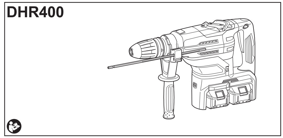


SPECIFICATIONS
| Model: | DHR400 | |
| Capacities | Carbide-tipped bit | 40 mm |
| Core bit | 105 mm | |
| No load speed (RPM) | 250 – 500 min.’ | |
| Blows per minute | 1,450 – 2,900 mind | |
| Overall length | 473 mm | |
| Rated voltage | D.C. 36 V | |
| Net weight | 7.3 – 8.1 kg | |
- Due to our continuing program of research and development, the specifications herein are subject to change without notice.
- Specifications and battery cartridges may differ from country to country.
- The weight may differ depending on the attachment(s), including the battery cartridge. The lightest and heaviest combinations, according to EPTA-Procedure 01/2014, are shown in the table.
Applicable battery cartridge
BL1815N / BL1820 / BL1820B / BL1830 / BL1830B / BL1840 / BL1840B / BL1850 / BL1850B / BL1860B
- Some of the battery cartridges listed above may not be available depending on your region of residence.

Intended use
The tool is intended for hammer drilling and drilling in brick, concrete, and stone as well as for chiseling work.
Noise
The typical A-weighted noise level determined according to
EN60745:
Sound pressure level (LpA) : 91 dB(A)
Sound power level (LWA) : 102 dB (A)
Uncertainty (K) : 3 dB(A)
Vibration
The vibration total value (tri-axial vector sum) determined according to
EN60745: Work mode: hammer drilling into concrete Vibration emission (ah, HD): 5.0 m/s2
Uncertainty (K) : 1.5 m/s2
Work mode: chiseling function with side grip
Vibration emission (ah, Cheq): 4.5 m/s2
Uncertainty (K) : 1.5 m/s2
Work mode: chiseling function with side handle
Vibration emission (ah, Cheq): 4.5 m/s2
Uncertainty (K) : 1.5 m/s2
NOTE: The declared vibration emission value has been measured in accordance with the standard test method and may be used for comparing one tool with another.
NOTE: The declared vibration emission value may also be used in a preliminary assessment of exposure.
EC Declaration of Conformity
For European countries only
The EC declaration of conformity is included as Annex A to this instruction manual.
SAFETY WARNINGS
General power tool safety warnings
Save all warnings and instructions for future reference.
The term “power tool” in the warnings refers to your mains-operated (corded) power tool or battery-operated (cordless) power tool.
CORDLESS ROTARY HAMMER SAFETY WARNINGS
- Wear ear protectors. Exposure to noise can cause hearing loss.
- Use auxiliary handle(s), if supplied with the tool. Loss of control can cause personal injury.
- Hold power tool by insulated gripping surfaces, when performing an operation where the cutting accessory may contact hidden wiring. Cutting accessory contacting a “live” wire may make exposed metal parts of the power tool “live” and could give the operator an electric shock.
- Wear a hard hat (safety helmet), safety glasses, and/or face shield. Ordinary eyes or sunglasses are NOT safety glasses. It is also highly recommended that you wear a dust mask and thickly padded gloves.
- Be sure the bit is secured in place before operation.
- Under normal operation, the tool is designed to produce vibration. The screws can come loose easily, causing a breakdown or accident. Check the tightness of screws carefully before operation.
- In cold weather or when the tool has not been used for a long time, let the tool warm up for a while by operating it under no load. This will loosen up the lubrication. Without proper warm-up, hammering operation is difficult.
- Always be sure you have a firm footing. Be sure no one is below when using the tool in high locations.
- Hold the tool firmly with both hands.
- Keep hands away from moving parts.
- Do not leave the tool running. Operate the tool only when hand-held.
- Do not point the tool at anyone in the area when operating. The bit could fly out and injure someone seriously.
- Do not touch the bit, parts close to the bit, or workpiece immediately after operation; they may be extremely hot and could burn your skin.
- Some material contains chemicals that may be toxic. Take caution to prevent dust inhalation and skin contact. Follow material supplier safety data.
- Always be sure that the tool is switched off and the battery cartridge and the bit are removed before handing the tool to another person.
SAVE THESE INSTRUCTIONS.
WARNING: DO NOT let comfort or familiarity with the product (gained from repeated use) replace strict adherence to safety rules for the subject product. MISUSE or failure to follow the safety rules stated in this instruction manual may cause serious personal injury.
Important safety instructions for battery cartridge
- Before using the battery cartridge, read all instructions and cautionary markings on (1) battery charger, (2) battery, and (3) product using the battery.
- Do not disassemble the battery cartridge.
- If the operating time has become excessively shorter, stop operating immediately. It may result in a risk of overheating, possible burns, and even an explosion.
- If electrolyte gets into your eyes, rinse them out with clear water and seek medical attention right away.
It may result in loss of your eyesight. - Do not short the battery cartridge: (1) Do not touch the terminals with any conductive material. (2) Avoid storing the battery cartridge in a container with other metal objects such as nails, coins, etc. (3) Do not expose the battery cartridge to water or rain.
A battery short can cause a large current flow, overheating, possible burns, and even a breakdown. - Do not store the tool and battery cartridge in locations where the temperature may reach or exceed 50 °C (122 °F).
- Do not incinerate the battery cartridge even if it is severely damaged or is completely worn out. The battery cartridge can explode in a fire.
- Be careful not to drop or strike the battery.
- Do not use a damaged battery.
- The contained lithium-ion batteries are subject to the Dangerous Goods Legislation requirements.
For commercial transports e.g. by third parties or forwarding agents, the special requirements on packaging and labeling must be observed.
For preparation of the item being shipped, consulting an expert for hazardous material is required. Please also observe possibly more detailed national regulations.
Tape or mask off open contacts and pack up the battery in such a manner that it cannot move around in the packaging. - Follow your local regulations relating to the disposal of batteries.
- Use the batteries only with the products specified by Makita. Installing the batteries to non-compliant products may result in a fire, excessive heat, explosion, or leak of electrolyte.
CAUTION: Only use genuine Makita batteries.
Use of non-genuine Makita batteries, or batteries that have been altered, may result in the battery bursting causing fires, personal injury, and damage. It will also void the Makita warranty for the Makita tool and charger.
Tips for maintaining maximum battery life
- Charge the battery cartridge before completely discharged. Always stop tool operation and charge the battery cartridge when you notice less tool power.
- Never recharge a fully charged battery cartridge. Overcharging shortens the battery service life.
- Charge the battery cartridge at room temperature at 10 °C – 40 °C (50 °F – 104 °F). Let a hot battery cartridge cool down before charging it.
- Charge the battery cartridge if you do not use it for a long period (more than six months).
Important safety instructions for the wireless unit
- Do not disassemble or tamper with the wireless unit.
- Keep the wireless unit away from young children.
If accidentally swallowed, seek medical attention immediately. - Use the wireless unit only with Makita tools.
- Do not expose the wireless unit to rain or wet conditions.
- Do not use the wireless unit in places where the temperature exceeds 50°C (122°F).
- Do not operate the wireless unit in places where medical instruments, such as heart pacemakers are nearby.
- Do not operate the wireless unit in places where automated devices are nearby. If operated, automated devices may develop malfunction or error.
- The wireless unit can produce electromagnetic fields (EMF) but they are not harmful to the user.
- The wireless unit is an accurate instrument. Be careful not to drop or strike the wireless unit.
- Avoid touching the terminal of the wireless unit with bare hands or metallic materials.
- Always remove the battery on the tool when installing the wireless unit.
- When opening the lid of the slot, avoid the place where dust and water may come into the slot. Always keep the inlet of the slot clean.
- Always insert the wireless unit in the correct direction.
- Do not press the wireless activation button on the wireless unit too hard and/or press the button with an object with a sharp edge.
- Always close the lid of the slot when operating.
- Do not remove the wireless unit from the slot while the power is being supplied to the tool.
Doing so may cause a malfunction of the wireless unit. - Do not remove the sticker on the wireless unit.
- Do not put any stickers on the wireless unit.
- Do not leave the wireless unit in a place where static electricity or electrical noise could be generated.
- Do not leave the wireless unit in a place subject to high heat, such as a car sitting in the sun.
- Do not leave the wireless unit in a dusty or powdery place or in a place corrosive gas could be generated.
- A sudden change of the temperature may bedew the wireless unit. Do not use the wireless unit until the dew is completely dried.
- When cleaning the wireless unit, gently wipe with a dry soft cloth. Do not use benzine, thinner, conductive grease or the like.
- When storing the wireless unit, keep it in the supplied case or a static-free container.
- Do not insert any devices other than Makita wireless unit into the slot on the tool.
- Do not use the tool with the lid of the slot damaged. Water, dust, and dirt coming into the slot may cause malfunction.
- Do not pull and/or twist the lid of the slot more than necessary. Restore the lid if it comes off from the tool.
- Replace the lid of the slot if it is lost or damaged.
FUNCTIONAL DESCRIPTION
Installing or removing the battery cartridge
► Fig.1: 1. Red indicator 2. Button 3. Battery cartridge
To remove the battery cartridge, slide it from the tool while sliding the button on the front of the cartridge.
To install the battery cartridge, align the tongue on the battery cartridge with the groove in the housing and slip it into place. Insert it all the way until it locks in place with a little click.
If you can see the red indicator on the upper side of the button, it is not locked completely.
Indicating the remaining battery capacity
Only for battery cartridges with the indicator
► Fig.2: 1. Indicator lamps 2. Check button
Press the check button on the battery cartridge to indicate the remaining battery capacity. The indicator lamps light up for a few seconds.

NOTE: Depending on the conditions of use and the ambient temperature, the indication may differ slightly from the actual capacity.
Tool/battery protection system
The tool is equipped with a tool/battery protection system. This system automatically cuts off power to the motor to extend tool and battery life. The tool will automatically stop during operation if the tool or battery is placed under one of the following conditions:
Overload protection
When the battery is operated in a manner that causes it to draw an abnormally high current, the tool automatically stops without any indication. In this situation, turn the tool off and stop the application that caused the tool to become overloaded. Then turn the tool on to restart.
Overheat protection
When the tool or battery is overheated, the tool stops automatically and the lamp blinks. In this case, let the tool and battery cool before turning the tool on again.
Overdischarge protection
When the battery capacity is not enough, the tool stops automatically. In this case, remove the battery from the tool and charge the battery.
Switch action
WARNING: Before installing the battery cartridge into the tool, always check to see that the switch trigger actuates properly and returns to the “OFF” position when released.
CAUTION: When not operating the tool, depress the trigger-lock button from
► Fig.3: 1. Switch trigger 2. Trigger-lock button
To prevent the switch trigger from being accidentally pulled, the trigger-lock button is provided. To start the tool, depress the trigger-lock button from the A-side and pull the switch trigger. Release the switch trigger to stop. After use, press the trigger-lock button from the B side.

Speed change
The revolutions and blows per minute can be adjusted by turning the adjusting dial. The dial is marked 1 (lowest speed) to 5 (full speed).
► Fig.4: 1. Adjusting dial
Refer to the table below for the relationship between the number on the adjusting dial and the revolutions and blows per minute.
| Number | Revolutions per minute | Blows per minute |
| 5 | 500 | 2,900 |
| 4 | 470 | 2,700 |
| 3 | 380 | 2,150 |
| 2 | 290 | 1,650 |
| 1 | 250 | 1,450 |
NOTICE: If the tool is operated continuously at low speed for a long time, the motor will get overloaded, resulting in tool malfunction.
NOTICE: The speed adjusting dial can be turned only as far as 5 and back to 1. Do not force it past 5 or 1, or the speed adjusting function may no longer work.
NOTE: When the speed adjusting dial is set to “3” or higher, the tool automatically reduces the speed at no-load to reduce the vibration under no-load. Once the operation starts with a bit against concrete, blows per minute increase and reach the numbers as shown in the table. When the temperature is low and there is less fluidity in grease, the tool may not have this function even with the motor rotating.
Lighting up the front lamp
► Fig.5: 1. Lamp
Pull the switch trigger to light up the lamp. The lamp keeps on lighting while the switch trigger is being pulled.
The lamp goes out approximately 10 seconds after releasing the switch trigger.
NOTE: Use a dry cloth to wipe the dirt off the lens of the lamp. Be careful not to scratch the lens or the lamp, or it may lower the illumination.
Selecting the action mode
NOTICE: Do not rotate the action mode changing knob when the tool is running. The tool will be damaged.
NOTICE: To avoid rapid wear on the mode change mechanism, be sure that the action mode changing knob is always positively located in one of the three action mode positions.
Rotation with hammering
For drilling in concrete, masonry, etc., rotate the action mode changing knob to the
► Fig.6: 1. Action mode changing knob 2. Pointer

Hammering only
For chipping, scaling or demolition operations, rotate the action mode changing knob to the
► Fig.7: 1. Pointer 2. Action mode changing knob
Torque limiter
NOTICE: As soon as the torque limiter actuates, switch off the tool immediately. This will help prevent premature wear of the tool.
NOTICE: Drill bits such as hole saw, which tend to pinch or catch easily in the hole, are not appropriate for this tool. This is because they will cause the torque limiter to actuate too frequently.
The torque limiter will actuate when a certain torque level is reached. The motor will disengage from the output shaft. When this happens, the drill bit will stop turning.
Constant speed control
Electronic speed control for obtaining constant speed.
Possible to get a fine finish, because the rotating speed is kept constant even under load conditions.
ASSEMBLY
Side handle
► Fig.8
CAUTION: Use the side handle only when chipping, scaling or demolishing. Do not use it when drilling in concrete, masonry, etc. The tool cannot be held properly with this side handle when drilling.
► Fig.9: 1. Side handle 2. Clamp nut
The side handle can be swung 360° on the vertical and secured at any desired position. It also secures at eight different positions back and forth on the horizontal. Loosen the clamp nut to swing the side handle to the desired position, and then tighten the clamp nut securely.
Side grip (auxiliary handle)
CAUTION: Always use the side grip to ensure safe operation.
CAUTION: After installing or adjusting the side grip, make sure that the side grip is firmly secured.
The side grip swings around to either side, allowing easy handling of the tool in any position. Loosen the side grip by turning it counterclockwise, swing it to the desired position and then tighten it by turning clockwise.
► Fig.10: 1. Side grip
Grease
Coat the shank end of the drill bit beforehand with a small amount of grease (about 0.5 – 1 g).
This chuck lubrication assures smooth action and long service life.
Installing or removing the drill bit
Clean the shank end of the drill bit and apply grease before installing the drill bit.
► Fig.11: 1. Shank end 2. Grease
Insert the drill bit into the tool. Turn the drill bit and push it in until it engages.
After installing the drill bit, always make sure that the drill bit is securely held in place by trying to pull it out.
► Fig.12: 1. Drill bit
To remove the drill bit, pull the chuck cover down all the way and pull the drill bit out.
► Fig.13: 1. Drill bit 2. Chuck cover
Chisel angle (when chipping, scaling or demolishing)
The chisel can be secured at the desired angle. To change the chisel angle, rotate the action mode changing knob to the O symbol. Turn the chisel to the desired angle.
► Fig.14:1. Action mode changing knob 2. Pointer
Rotate the action mode changing knob to the
Depth gauge
The depth gauge is convenient for drilling holes of uniform depth.
Press and hold the lock button, and then insert the depth gauge into the hex hole.
► Fig.15: 1. Depth gauge 2. Lock button
Make sure that the toothed side of the depth gauge faces the marking.
► Fig.16: 1. Marking 2. Toothed side
Adjust the depth gauge by moving it back and forth while pressing the lock button. After the adjustment, release the lock button to lock the depth gauge.
NOTE: Make sure that the depth gauge does not touch the main body of the tool when attaching it.
Dust extractor attachment
Optional accessory
Installing the dust extractor attachment
- Loosen the side grip on the tool.
- Install the dust cover so that the claws of the dust cover fit in the grooves between the tool and the side grip.
► Fig.17: 1. Dust cover 2. Claw 3. Groove - Tighten the side grip securely.
- Set the suitable bellows or dust cover extension for your work. When you use bellows, attach the joint to its top. When you stack two bellows, connect them with the joint.
► Fig.18: 1. Dust cover extension 2. Dust cover 3. Joint 4. Bellows
Connecting the tool to the vacuum cleaner
- Attach the holder joint to the tool, and then attach the hose holder to the holder’s joint.
► Fig.19: 1. Holder joint 2. Hose holder - Fix the hose to the hose holder.
► Fig.20: 1. Hose holder
NOTE: Use joint 25 to connect the hose and the dust cover if necessary.
Using depth gauge for drilling operation
When you stack two bellows, attach the depth gauge extension to the depth gauge.
► Fig.21: 1. Depth gauge extension
Dust extractor attachment (for hammering only)
Optional accessory
- Install the hose holder.
When the side handle is installed to tool, loosen the clamp nut, and then remove the hex bolt. Install the hose holder with the hex bolt and the clamp nut by tightening the clamp nut firmly.
► Fig.22: 1. Bolt 2. Hose holder 3. Clamp nut
When the side grip is installed to the tool, loosen the side grip, mount the hose holder to the shaft, and then tighten the side grip firmly.
► Fig.23: 1. Hose holder 2. Shaft 3. Side grip - Attach the holder joint to the tool, and then attach the hose holder to the holder joint.
► Fig.24: 1. Holder joint 2. Hose holder - Attach the dust cover and the hose to the tool, and then fix the hose to the hose holders.
► Fig.25: 1. Dust cover 2. Hose 3. Hose holder - Connect the hose to the hose of the vacuum cleaner with the hose joint.
NOTE: If the hose is not included, attach the dust cover to the cleaner’s joint or attach it to Makita’s hose ø28. - Adjust the distance between the dust cover and the tip of the chisel or bull point. The recommended distance is 30 mm to 100 mm.
► Fig.26: (1) 30 mm to 100 mm
OPERATION
NOTE: If the battery cartridge is at a low temperature, the tool’s capability may not be fully obtained. In this case, warm up the battery cartridge by using the tool with no load for a while to fully obtain the tool’s capability.
Hammer drilling operation
Set the action mode changing knob to the
Do not apply more pressure when the hole becomes clogged with chips or particles. Instead, run the tool at an idle, then remove the drill bit partially from the hole. By repeating this several times, the hole will be cleaned out and normal drilling may be resumed.
NOTE: Eccentricity in the drill bit rotation may occur while operating the tool with no load. The tool automatically centers itself during operation. This does not affect the drilling precision.
Chipping/Scaling/Demolition
Set the action mode changing knob to the symbol.
Hold the tool firmly with both hands. Turn the tool on and apply slight pressure on the tool so that the tool will not bounce around, uncontrolled.
Pressing very hard on the tool will not increase efficiency.
► Fig.28
Blow-out bulb
Optional accessory
After drilling the hole, use the blow-out bulb to clean dust out of the hole.
► Fig.29
WIRELESS ACTIVATION FUNCTION
Optional accessory
What you can do with the wireless activation function
The wireless activation function enables clean and comfortable operation. By connecting a supported vacuum cleaner to the tool, you can run the vacuum cleaner automatically along with the switch operation of the tool.
► Fig.30
To use the wireless activation function, prepare the following items:
- A wireless unit (optional accessory)
- A vacuum cleaner that supports the wireless activation function
The overview of the wireless activation function setting is as follows. Refer to each section for detailed procedures.
- Installing the wireless unit
- Tool registration for the vacuum cleaner
- Starting the wireless activation function
Installing the wireless unit
Optional accessory
NOTICE: Clean the dust and dirt on the tool before installing the wireless unit. Dust or dirt may cause malfunction if it comes into the slot of the wireless unit.
NOTICE: To prevent the malfunction caused by static, touch a static discharging material, such as a metal part of the tool, before picking up the wireless unit.
NOTICE: When installing the wireless unit, always be sure that the wireless unit is inserted in the correct direction and the lid is completely closed.
- Open the lid on the tool as shown in the figure.
► Fig.31: 1. Lid - Insert the wireless unit to the slot and then close the lid.
When inserting the wireless unit, align the projections with the recessed portions on the slot.
► Fig.32: 1. Wireless unit 2. Projection - Lid
- Recessed portion
When removing the wireless unit, open the lid slowly.
The hooks on the back of the lid will lift the wireless unit as you pull up the lid.
► Fig.33: 1. Wireless unit 2. Hook 3. Lid
After removing the wireless unit, keep it in the supplied case or a static-free container.
NOTICE: Always use the hooks on the back of the lid when removing the wireless unit. If the hooks do not catch the wireless unit, close the lid completely and open it slowly again.
Tool registration for the vacuum cleaner
NOTE: A Makita vacuum cleaner supporting the wireless activation function is required for the tool registration.
NOTE: Finish installing the wireless unit to the tool before starting the tool registration.
NOTE: During the tool registration, do not pull the switch trigger or turn on the power switch on the vacuum cleaner.
NOTE: Refer to the instruction manual of the vacuum cleaner, too.
If you wish to activate the vacuum cleaner along with the switch operation of the tool, finish the tool registration beforehand.
- Install the batteries to the vacuum cleaner and the tool.
- Set the standby switch on the vacuum cleaner to “AUTO”.
► Fig.34: 1. Stand-by switch - Press the wireless activation button on the vacuum cleaner for 3 seconds until the wireless activation lamp blinks in green. And then press the wireless activation button on the tool in the same way. ► Fig.35: 1. Wireless activation button 2. Wireless activation lamp
If the vacuum cleaner and the tool are linked successfully, the wireless activation lamps will light up in green for 2 seconds and start blinking in blue.
NOTE: The wireless activation lamps finish blinking in green after 20 seconds elapsed. Press the wireless activation button on the tool while the wireless activation lamp on the cleaner is blinking. If the wireless activation lamp does not blink in green, push the wireless activation button briefly and hold it down again.
NOTE: When performing two or more tool registrations for one vacuum cleaner, finish the tool registration one by one.
Starting the wireless activation function
NOTE: Finish the tool registration for the vacuum cleaner prior to the wireless activation.
NOTE: Refer to the instruction manual of the vacuum cleaner, too.
After registering a tool to the vacuum cleaner, the vacuum cleaner will automatically run along with the switch operation of the tool.
- Install the wireless unit to the tool.
- Connect the hose of the vacuum cleaner with the tool.
► Fig.36 - Set the standby switch on the vacuum cleaner to “AUTO”.
► Fig.37: 1. Stand-by switch - Push the wireless activation button on the tool briefly. The wireless activation lamp will blink in blue.
► Fig.38: 1. Wireless activation button 2. Wireless activation lamp - Pull the switch trigger of the tool. Check if the vacuum cleaner runs while the switch trigger is being pulled.
To stop the wireless activation of the vacuum cleaner, push the wireless activation button on the tool.
NOTE: The wireless activation lamp on the tool will stop blinking in blue when there is no operation for 2 hours. In this case, set the standby switch on the vacuum cleaner to “AUTO” and push the wireless activation button on the tool again.
NOTE: The vacuum cleaner starts/stops with a delay.
There is a time lag when the vacuum cleaner detects a switch operation of the tool.
NOTE: The transmission distance of the wireless unit may vary depending on the location and surrounding circumstances.
NOTE: When two or more tools are registered to one vacuum cleaner, the vacuum cleaner may start running even if you don’t pull the switch trigger because another user is using the wireless activation function.
Description of the wireless activation lamp status
► Fig.39: 1. Wireless activation lamp
The wireless activation lamp shows the status of the wireless activation function. Refer to the table below for the meaning of the lamp status.
| Status | Wireless activation lamp | Description | |||
| Color | Duration | ||||
| Standby | Blue | 2 hours | The wireless activation of the vacuum cleaner is available. The lamp will automatically turn off when no operation is performed for 2 hours. | ||
| When the tool is running. |
The wireless activation of the vacuum cleaner is available and the tool is running. | ||||
| Tool registration |
Green | 20 seconds | Ready for the tool registration. Waiting for the registration by the vacuum cleaner. | ||
| 2 seconds | The tool registration has been finished. The wireless activation lamp will start blinking in blue. | ||||
| Canceling tool registration |
Red | 20 seconds | Ready for the cancellation of the tool registration. Waiting for the cancellation by the vacuum cleaner. | ||
| 2 seconds | The cancellation of the tool registration has been finished. The wireless activation lamp will start blinking in blue. | ||||
| Others | Red | 3 seconds | The power is supplied to the wireless unit and the wireless activation function is starting up. | ||
| Off | – | – | The wireless activation of the vacuum cleaner is stopped. | ||


Canceling tool registration for the vacuum cleaner
Perform the following procedure when canceling the tool registration for the vacuum cleaner.
- Install the batteries to the vacuum cleaner and the tool.
- Set the standby switch on the vacuum cleaner to “AUTO”.
► Fig.40: 1. Stand-by switch - Press the wireless activation button on the vacuum cleaner for 6 seconds. The wireless activation lamp blinks in green and then becomes red. After that, press the wireless activation button on the tool in the same way.
► Fig.41:1. Wireless activation button 2. Wireless activation lamp If the cancellation is performed successfully, the wireless activation lamps will light up in red for 2 seconds and start blinking in blue.
NOTE: The wireless activation lamps finish blinking in red after 20 seconds elapsed. Press the wireless activation button on the tool while the wireless activation lamp on the cleaner is blinking. If the wireless activation lamp does not blink in red, push the wireless activation button briefly and hold it down again.
Troubleshooting for the wireless activation function
Before asking for repairs, conduct your own inspection first. If you find a problem that is not explained in the manual, do not attempt to dismantle the tool. Instead, ask Makita Authorized Service Centers, always using Makita replacement parts for repairs.
| State of abnormality | Probable cause (malfunction) | Remedy |
| The wireless activation lamp does not light/blink. | The wireless unit is not installed into the tool. The wireless unit is improperly installed into the tool. |
Install the wireless unit correctly. |
| The terminal of the wireless unit and/or the slot is dirty. | Gently wipe off dust and dirt on the terminal of the wireless unit and clean the slot. | |
| The wireless activation button on the tool has not been pushed. | Push the wireless activation button on the tool briefly. | |
| The standby switch on the vacuum cleaner is not set to “AUTO”. | Set the standby switch on the vacuum cleaner to “AUTO”. | |
| No power supply | Supply the power to the tool and the vacuum cleaner. | |
| Cannot finish tool registration/can- ceiling tool registration successfully. |
The wireless unit is not installed into the tool. The wireless unit is improperly installed into the tool. |
Install the wireless unit correctly. |
| The terminal of the wireless unit and/or the slot is dirty. | Gently wipe off dust and dirt on the terminal of the wireless unit and clean the slot. | |
| The standby switch on the vacuum cleaner is not set to “AUTO”. | Set the standby switch on the vacuum cleaner to “AUTO”. | |
| No power supply | Supply the power to the tool and the vacuum cleaner. | |
| Incorrect operation | Push the wireless activation button briefly and perform the tool registration/cancellation procedures again. | |
| The tool and vacuum cleaner is away from each other (out of the transmission range). | Get the tool and vacuum cleaner closer to each other. The maximum transmission distance is approximately 10 m however it may vary according to the circumstances. | |
| Before finishing the tool registration/ cancellation; – the switch trigger on the tool is pulled or; – the power button on the vacuum cleaner is turned on. |
Push the wireless activation button briefly and perform the tool registration/cancellation procedures again. | |
| The tool registration procedures for the tool or vacuum cleaner have not been finished. | Perform the tool registration procedures for both the tool and the vacuum cleaner at the same time. | |
| Radio disturbance by other appliances generates high-intensity radio waves. | Keep the tool and vacuum cleaner away from the appliances such as Wi-Fi devices and microwave ovens. | |
| The vacuum cleaner does not run along with the switch operation of the tool. | The wireless unit is not installed into the tool. The wireless unit is improperly installed into the tool. |
Install the wireless unit correctly. |
| The terminal of the wireless unit and/or the slot is dirty. | Gently wipe off dust and dirt on the terminal of the wireless unit and clean the slot. | |
| The wireless activation button on the tool has not been pushed. | Push the wireless activation button briefly and make sure that the wireless activation lamp is blinking in blue. | |
| The standby switch on the vacuum cleaner is not set to “AUTO”. | Set the standby switch on the vacuum cleaner to “AUTO”. | |
| More than 10 tools are registered to the vacuum cleaner. | Perform the tool registration again. If more than 10 tools are registered to the vacuum cleaner, the tool registered earliest will be canceled automatically. | |
| The vacuum cleaner erased all tool registrations. | Perform the tool registration again. | |
| No power supply | Supply the power to the tool and the vacuum cleaner. | |
| The tool and vacuum cleaner is away from each other (out of the transmission range). | Get the tool and vacuum cleaner closer to each other. The maximum transmission distance is approximately 10 m however it may vary according to the circumstances. | |
| Radio disturbance by other appliances generates high-intensity radio waves. | Keep the tool and vacuum cleaner away from the appliances such as Wi-Fi devices and microwave ovens. | |
| The vacuum cleaner runs while the tool’s switch trigger is not pulled. | Other users are using the wireless activation of the vacuum cleaner with their tools. | Turn off the wireless activation button of the other tools or cancel the tool registration of the other tools. |
MAINTENANCE
NOTICE: Never use gasoline, benzene, thinner, alcohol, or the like. Discoloration, deformation, or cracks may result.
To maintain product SAFETY and RELIABILITY, repairs, and any other maintenance or adjustment should be performed by Makita Authorized or Factory Service Centers, always using Makita replacement parts.
OPTIONAL ACCESSORIES
If you need any assistance with more details regarding these accessories, ask your local Makita Service Center.
| • SDS-MAX Carbide-tipped drill bits | • Side grip |
| • SDS-MAX bull point | • Depth gauge |
| • SDS-MAX cold chisel | • Blow-out bulb |
| • SDS-MAX scaling chisel | • Dust extractor attachment |
| • SDS-MAX clay spade | • Safety goggles |
| • Hammer grease | • Wireless unit |
| • Bit grease | • Makita genuine battery and charger |
| • Side handle | • Plastic carrying case |
NOTE: Some items in the list may be included in the tool package as standard accessories. They may differ from country to country.
Makita Europe N.V.
Jan-Baptist Vinkstraat 2,
3070 Kortenberg, Belgium
Makita Corporation
3-11-8, Sumiyoshi-cho,
Anjo, Aichi 446-8502 Japan
www.makita.com
885622-992
EN, FR, DE, IT, NL,
ES, PT, DA, EL, TR
20170915