Bosch GIC 120 Inspection camera Instruction Manual


BOSCH GIC 120 Inspection Camera

Accessories


Safety Notes
Digital Inspection Camera
Read all safety warnings and all instructions.
Failure to follow the warnings and instructions may result in electric shock, fire and/or serious injury.
- Have the inspection camera repaired only through a qualified repair person and only using identical re-placement parts. This will ensure that the safety of the inspection camera is maintained.
- Do not operate the inspection camera in explosive atmospheres, such as in the presence of flammable liquids, gases or dusts. Sparks can be created in the inspection camera which may ignite the dust or fumes.
- Do not direct the light beam at persons or animals and do not stare into the light beam yourself (not even from a distance).
- Check the working range before using the inspection camera. No part of the inspection camera may come in-to contact with electrical lines, moving parts or chemicals substances. Interrupt the power circuit of electrical lines in the working range. These measures reduce the risk of explosion, electric shock and property damage.
- Wear appropriate protective equipment such as safety glasses/goggles, protective gloves or respirator when materials that are hazardous to one’s health are in the working range. Sewer lines or similar areas can contain solid, liquid or gaseous substances, which may be toxic, infectious, caustic or otherwise hazard to one’s health.
- Pay particular attention to cleanness when working in areas with substances that are hazardous to one’s health. Do not eat during work. Avoid contact with sub-stances that are hazardous to one’s health. After finishing your work, wash hands and other affected body parts that may have come into contact, with warm soapy water.
- Do not stand in water when using the inspection cam-era. When standing in water while working, there is a risk of electric shock.
Magnet
Keep the magnet 16 away from cardiac pacemakers. The magnet generates a field that can impair the function of cardiac pace-makers.
- Keep the magnet 16 away from magnetic data medium and magnetically-sensitive equipment. The effect of the magnetic can lead to irreversible data loss.
Product Description and Specifications
While reading the operating instructions, unfold the fold-out page with the illustration of the inspection camera and leave it open.
Intended Use
The digital inspection camera is suitable for inspecting hard to reach locations or dark areas. After mounting the provided accessories to the camera head, it is also suitable for moving and removing small and light objects (e.g., small screws). The digital inspection camera may not be used for medicinal purposes. It is also not suitable for repairing pipe clogs or pulling in cables.
The light in the camera head is intended to illuminate the direct work area of the digital inspection camera and is not suit-able for household room illumination.
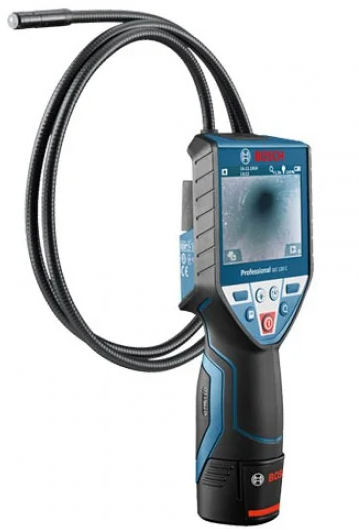
Product Features
The numbering of the product features refers to the illustration of the inspection camera on the graphics page.
- Hand unit
- On/Off button
- Black-and-white button
- Lighting/brightness button
- Display
- Magnification button
- Camera cable
- Camera head
- Illumination light in camera head
- Camera lens
- Pull-out battery compartment
- Battery lid
- Latch of battery lid
- Camera connection
- Camera cable lock
- Magnet
- Hook
- Mirror
Display Elements
- Status bar
- Selected magnification
- Selected lighting/brightness
- Battery indicator
- Compass View with reference point (Up Indicator)
- Accessories shown or described are not part of the standard de-livery scope of the product. A complete overview of accessories can be found in our accessories program.
Technical Data
| Digital Inspection Camera | GIC 120 | |
| Article number | 3 601 B41 1.. | |
| Rated voltage | V= | 6.0 |
| Operating temperature | °C | –10…+50 |
| Storage temperature (hand unit without batteries) | °C | –20…+60 |
| Relative humidity | % | 5–951) |
| Smallest bending radius of camera cable | mm | 25 |
| Diameter of camera head | mm | 8.5 |
| Display resolution | 320 x 240 | |
| Operating time, approx. | h | 5.02) |
| Weight according to EPTA-Procedure 01:2014 | kg | 0.50 |
| Dimensions (length x width x height) | mm | 197 x 85 x 49 |
Assembly
Inserting/Replacing the Batteries
It is recommended that you use alkali-manganese batteries to operate the inspection camera.
To open the battery lid 12, press the latch 13 and fold open the battery lid 12. Pull out the battery compartment 11 and insert the batteries. When inserting, pay attention to the correct polarity according to the representation on the inside of the battery compartment 11. Slide the battery compartment 11 all the way in and close the battery lid 12.
The symbol will initially appear on the display if the charging condition of the batteries is low. When the battery symbol is empty, you have to replace the batteries because inspections are no longer possible.
Always replace all batteries at the same time. Only use batter-ies from one brand and with the identical capacity.
- Remove the batteries from the inspection camera when not using it for a prolonged period of time. The batteries can corrode and self-discharge during prolonged storage.
Mounting the Camera Cable (see figure A)
For operation of the inspection camera, the camera cable 7 must be mounted to the hand unit 1.
Attach the plug of the camera cable 7 to the camera connection 14 in the correct position until it engages.
Dismounting the Camera Cable (see figure B)
To remove the camera cable 7, press the lock 15 together and pull the plug out of the hand unit 1.
Mounting the Mirror, Magnet or Hook (see figure C)
The mirror 18, the magnet 16 and the hook 17 can be mount-ed to the camera head 8 as auxiliary aids.
Slide one of the three auxiliary aids to the stop onto the recess on the camera head 8 as shown in the figure.
Note: The magnet 16 and the hook 17 are only suitable for moving and removing loose, small and light objects. Applying too much tension can damage the inspection camera or the auxiliary aid.
Operation
- Keep the hand unit 1 and the batteries dry and protect them from direct sunlight. The camera cable and camera head are waterproof when mounted correctly. However, the hand unit and the batteries are not protected against water. If they come into contact with water, there is a risk of electric shock or damage.
- Do not subject the inspection camera to extreme temperatures or variations in temperature. As an example, do not leave it in vehicles for longer periods. In case of large variations in temperature, allow the inspection cam-era to adjust to the ambient temperature before putting it into operation.
- Do not use the inspection camera when the lens on the camera head 8 is misty or fogged-up. Do not switch the inspection camera on until after the moisture has evaporated. Otherwise, the inspection camera can become damaged.
- The switched-on illumination light 9 can become hot during operation. In order to prevent burns, do not touch the illumination light.
Initial Operation
Switching On and Off
To switch on the inspection camera, press the On/Off button 2. The start screen will be shown on the display 5 for a short time.
Note: If the camera cable is not mounted when the tool is switched on, the display will show an error message.
To switch off the inspection camera, press the On/Off button 2 again.
If no button is pressed on the inspection camera for approx. 20 mins, it will automatically switch off to save the batteries.
Regulating the Illumination Light in the Camera Head
To brighten the camera image, you can switch on the illumination light 9 in the camera head and adjust the brightness.
The brightness can be adjusted in 4 stages (0 %, 25 %, 50 %, 100 %).
To switch on the camera illumination light 9 and to increase the brightness, press button 4 repeatedly until the required brightness is reached.
- Do not stare into the illumination light 9 and do not di-rect it at other persons. The brightness of the light can blind the eyes.
To reduce the brightness and to switch off the camera illumi-nation light 9, press button 4 repeatedly until the required brightness is reached or the illumination light is switched off.
Magnifying the Image on the Display (Zoom)
Briefly pressing button 6 magnifies the image on the display by a factor of 1.5 or 2.
Black-And-White Button
Briefly pressing button 3 switches the display between col-our rendering and black-and-white rendering. Using black-and-white rendering can, for example, improve the contrast.
Compass View with Reference Point (Up Indicator) (see figure D)
Holding down button 3 takes you to the Compass View e. When doing so, the yellow reference point (Up Indicator) shows you where the physical “up” position is in the image.
Note: Restricted function when mirror 18 is mounted and/or when camera cable 7 is aligned vertically.
Status Bar
The status bar a is shown on the display for approx. 2 seconds after every button press. It shows:
- the selected magnification (b)
- the selected brightness (c)
- the charging condition of the batteries (d).
Working Advice
Check the area that you want to inspect and pay particular attention to obstructions or hazard areas.
Bend the camera cable 7 in such a manner that the camera head can be easily inserted into the area subject to the inspection. Carefully guide the camera cable in.
Adjust the brightness of the illumination light 9 so that the image can be seen well. For heavily reflecting objects, as an example, less light will provide a better image.
When objects to be inspected are represented unship, re-duce or increase the distance between camera head 8 and object.
Maintenance and Service
Maintenance and Cleaning
Do not immerse the hand unit 1 into water or other fluids.
Keep the inspection camera clean at all times. Clean the inspection camera and all auxiliary aids particularly thorough after having worked in areas with substances that are hazardous to one’s health.
Wipe off debris using a moist and soft cloth. Do not use any cleaning agents or solvents.
Especially clean the lens 10 of the camera regularly and pay attention for any lint.
After-sales Service and Application Service
In all correspondence and spare parts orders, please always include the 10-digit article number given on the type plate of the inspection camera.
Our after-sales service responds to your questions concerning maintenance and repair of your product as well as spare parts. Exploded views and information on spare parts can al-so be found under: www.bosch-pt.com
Bosch’s application service team will gladly answer questions concerning our products and their accessories.
Great Britain
Robert Bosch Ltd. (B.S.C.)
P.O. Box 98
Broadwater Park
North Orbital Road
Denham
Uxbridge
UB 9 5HJ
At www.bosch-pt.co.uk you can order spare parts or arrange the collection of a product in need of servicing or repair.
Tel. Service: (0344) 7360109
Email:
Ireland
Origo Ltd.
Unit 23 Magna Drive
Magna Business Park
City West
Dublin 24
Tel. Service: (01) 4666700
Fax: (01) 4666888
Australia, New Zealand and Pacific Islands
Robert Bosch Australia Pty. Ltd.
Power Tools
Locked Bag 66
Clayton South VIC 3169
Customer Contact Center
Inside Australia:
Phone: (01300) 307044
Fax: (01300) 307045
Inside New Zealand:
Phone: (0800) 543353
Fax: (0800) 428570
Outside AU and NZ:
Phone: +61 3 95415555
www.bosch.com.au
Republic of South Africa
Customer service
Hotline: (011) 6519600
Gauteng – BSC Service Centre
35 Roper Street, New Centre Johannesburg
Tel.: (011) 4939375
Fax: (011) 4930126
E-Mail:
KZN – BSC Service Centre
Unit E, Almar Centre
143 Crompton Street
Pinetown
Tel.: (031) 7012120
Fax: (031) 7012446
E-Mail:
Western Cape – BSC Service Centre
Democracy Way, Prosperity Park Milnerton
Tel.: (021) 5512577
Fax: (021) 5513223
E-Mail:
Bosch Headquarters
Midrand, Gauteng
Tel.: (011) 6519600
Fax: (011) 6519880
E-Mail:
People’s Republic of China
China Mainland
Bosch Power Tools (China) Co., Ltd.
567, Bin Kang Road
Bin Jiang District 310052
Hangzhou, P.R.China
Service Hotline: 4008268484
Fax: (0571) 87774502
E-Mail:
www.bosch-pt.com.cn
HK and Macau Special Administrative Regions
Robert Bosch Hong Kong Co. Ltd.
21st Floor, 625 King’s Road
North Point, Hong Kong
Customer Service Hotline: +852 2101 0235
Fax: +852 2590 9762
E-Mail:
www.bosch-pt.com.hk
Indonesia
PT Robert Bosch
Palma Tower 9th & 10th Floor
Jl. Let. Jend. TB Simatupang II S/06
Jakarta Selatan 12960
Indonesia
Tel.: (021) 3005 6565
Fax: (021) 3005 5801
E-Mail:
www.bosch-pt.co.id
Philippines
Robert Bosch, Inc.
28th Floor Fort Legend Towers,
3rd Avenue corner 31st Street,
Fort Bonifacio Global City,
1634 Taguig City, Philippines
Tel.: (02) 8703871
Fax: (02) 8703870
Email:
www.bosch-pt.com.ph
Bosch Service Center:
9725-27 Kamagong Street
San Antonio Village
Makati City, Philippines
Tel.: (02) 8999091
Fax: (02) 8976432
Email:
Malaysia
Robert Bosch (S.E.A.) Sdn. Bhd.
No. 8A, Jalan 13/6
G.P.O. Box 10818
46200 Petaling Jaya
Selangor, Malaysia
Tel.: (03) 79663194
Fax: (03) 79583838
Email:
Toll-Free: 1800 880188
www.bosch-pt.com.my
Thailand
Robert Bosch Ltd.
Liberty Square Building
No. 287, 11 Floor
Silom Road, Bangrak
Bangkok 10500
Tel.: 02 6393111, 02 6393118
Fax: 02 2384783
Robert Bosch Ltd., P. O. Box 2054
Bangkok 10501, Thailand
www.bosch.co.th
Bosch Service – Training Centre
La Salle Tower Ground Floor Unit No.2
10/11 La Salle Moo 16
Srinakharin Road
Bangkaew, Bang Plee
Samutprakarn 10540
Thailand
Tel.: 02 7587555
Fax: 02 7587525
Singapore
Robert Bosch (SEA) Pte. Ltd.
11 Bishan Street 21
Singapore 573943
Tel.: 6571 2772
Fax: 6350 5315
Toll-Free: 1800 3338333
www.bosch-pt.com.sg
Vietnam
Robert Bosch Vietnam Co. Ltd
10/F, 194 Golden Building
473 Dien Bien Phu Street
Ward 25, Binh Thanh District
84 Ho Chi Minh City
Vietnam
Tel.: (08) 6258 3690 ext. 413
Fax: (08) 6258 3692
www.bosch-pt.com
Disposal
The inspection camera, batteries, accessories and packaging should be sorted for environmental-friendly recycling.
Do not dispose of inspection cameras and battery packs/batteries into household waste!
Only for EC countries:
According to the European Guideline 2012/19/EU, electrical devices/tools that are no longer usable, and according to the European Guideline 2006/66/EC, defective or used battery packs/batteries, must be collected separately and disposed of in an environmentally correct manner.
Batteries no longer suitable for use can be directly returned at:
Great Britain
Robert Bosch Ltd. (B.S.C.)
P.O. Box 98
Broadwater Park
North Orbital Road
Denham
Uxbridge
UB 9 5HJ
At www.bosch-pt.co.uk you can order spare parts or arrange the collection of a product in need of servicing or repair.
Tel. Service: (0344) 7360109
E-Mail:
Subject to change without notice.