Bosch GOL 32 D Optical level Instruction Manual


BOSCH GOL 32 D Optical level


Safety Notes
Read and observe all instructions. SAVE THESE INSTRUCTIONS FOR FUTURE REFER-ENCE.
- Have the measuring tool repaired only through qualified specialists using original spare parts. This ensures that the safety of the measuring tool is maintained
Technical Data |
||||||
| Automatic level | GOL 20 D | GOL 20 G | GOL 26 D | GOL 26 G | GOL 32 D | GOL 32 G |
| Article number | 3 601 K68 400 | 3 601 K68 401 | 3 601 K68 000 | 3 601 K68 001 | 3 601 K68 500 | 3 601 K68 501 |
| Working range | 60 m | 60 m | 100 m | 100 m | 120 m | 120 m |
| Height accuracy for an individual measurement |
3 mm/30 m |
3 mm/30 m |
1,6 mm/30 m |
1,6 mm/30 m |
1 mm/30 m |
1 mm/30 m |
| Deviation for 1 km double run leveling |
2,5 mm |
2,5 mm |
1,5 mm |
1,5 mm |
1,0 mm |
1,0 mm |
| Accuracy of the bubble vial |
8´/2 mm |
8´/2 mm |
8´/2 mm |
8´/2 mm |
8´/2 mm |
8´/2 mm |
| Compensator Levelling range |
±15´ |
±15´ |
±15´ |
±15´ |
±15´ |
±15´ |
| Magnet dampening | l | l | l | l | l | l |
Product Description and Specifications
Please unfold the fold-out page with the representation of the measuring tool and leave it unfolded while reading the operat-ing instructions.
Intended Use
The measuring tool is intended for determining and checking precise horizontal partitions. It is also suitable for measuring heights, distances and angles.
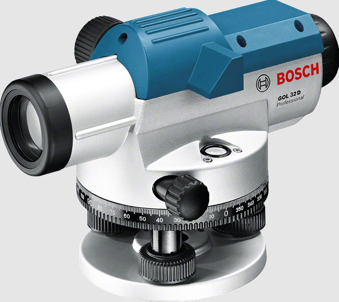
Product Features
The numbering of the product features shown refers to the il-lustration of the measuring tool on the graphic page.
- Objective lens
- Optical peep sight
- Bubble vial mirror
- Eyepiece cover
- Adjusting screw for sighting line
- Eyepiece
- Circular bubble vial
- Compensator lock
- Horizontal circle reference mark
- Horizontal circle
- Adjusting screw of circular bubble vial
- Levelling screw
- Tripod mount 5/8″ (on the rear side)
- Horizontal drive screw
- Serial number
- Focusing knob
- Hex key
- Adjusting pin
- Case
- Plumb-bob
The accessories illustrated or described are not included as standard delivery.
|
erect 20x 1°30´
36 mm
0.3 m 100 0 |
erect 20x 1°30´
36 mm
0.3 m 100 0 |
erect 26x 1°30´
36 mm
0.3 m 100 0 |
erect 26x 1°30´
36 mm
0.3 m 100 0 |
erect 32x 1°30´
36 mm
0.3 m 100 0 |
erect 32x 1°30´
36 mm
0.3 m 100 0 |
| Horizontal circle graduation | 1° |
1 gon |
1° |
1 gon |
1° |
1 gon |
| Tripod mount | 5/8″ | 5/8″ | 5/8″ | 5/8″ | 5/8″ | 5/8″ |
| Weight according to EPTA-Procedure 01:2014 |
1.5 kg |
1.5 kg |
1.5 kg |
1.5 kg |
1.5 kg |
1.5 kg |
Operation
- Check the levelling and indication accuracy of the measuring tool each time before using and after longer transport of the measuring tool.
- Protect the measuring tool against moisture and direct sun light.
- Do not subject the measuring tool to extreme temperatures or variations in temperature. As an example, do not leave it in vehicles for a long time. In case of large variations in temperature, allow the measuring tool to adjust to the ambient temperature before putting it into operation. In case of extreme temperatures or variations in temperature, the accuracy of the measuring tool can be impaired.
- Avoid any impact to or dropping of the measuring tool. After severe exterior effects to the measuring tool, it is recommended to carry out an accuracy check (see “Accuracy Check of the Measuring Tool”, page 10) each time before continuing to work.
- Place the measuring tool in the provided case when transporting it over larger distances (e.g. in the car). Ensure that the measuring tool is correctly placed in the transport case. When placing the measuring tool in the case, the compensator is locked; otherwise, it could be damaged in case of intense movement.
Setting Up/Aligning the Measuring Tool
Mounting on the Tripod
Set up the tripod stable and safe against tipping over or slip-ping off. Place the measuring tool via the tripod mount 13 on-to the male thread of the tripod and screw the measuring tool tight with the locking screw of the tripod.
Roughly level the tripod.
Over short distances, the measuring tool can be carried mounted on the tripod. To ensure that the measuring tool is not damaged during this, the tripod must be held vertically during transport, and should not be carried lengthwise over the shoulder.
Aligning the Measuring Tool
Align the measuring tool with the levelling screws 12 so that the air bubble is positioned in the center of the circular bubble vial 7.

Turn the first two levelling screws A and B to move the air bubble so that it is centered between the two levelling screws. Then turn the third levelling screw C until the air bubble is positioned in the center of the circular bubble vial.
Any remaining deviation of the measuring tool to the horizontal plane following the balancing of the circular bubble vial is compensated by means of the compensator.
While working, regularly check (e.g. by viewing through the bubble vial mirror 3) whether the air bubble is still in the centre of the circular bubble vial.
Centering the Measuring Tool over a Point on the Ground
If required, center the measuring tool over a point on the ground. For this, hang the plumb-bob 20 onto the locking screw of the tripod. Align the measuring tool above the point on the ground either by moving the measuring tool on the tri-pod or by adjusting the tripod.
Focusing the Telescope
Remove the lens cap from the objective lens 1.

Direct the telescope against a bright object or hold a white sheet of paper in front of the objective lens 1. Turn the eyepiece 6 until the crosshair appears sharp and deep black.
Direct the telescope towards the levelling rod, if required with help of the optical peep sight 2. Turn the focusing knob 16 un-til the graduation field of the levelling rod appears sharp. Align the crosshair exactly with the center of the levelling rod by turning the horizontal drive screw 14.When the telescope is correctly focussed, the crosshair and the image of the levelling rod must remain aligned when moving your eye behind the eyepiece.
Measuring Functions
Always set up the levelling rod exactly vertical. Direct the aligned and focused measuring tool against the levelling rod in such a manner that the crosshair faces centrally against the levelling rod.
Reading Off the Height

Read off the height of the levelling rod at the center line of the crosshair.
Height measured in the figure: 1.195 m.
Measuring a Distance

Centre the measuring tool above the point from which on the distance is to be measured.
Read off the height of the levelling rod at the top and bottom stadia lines. Multiply the difference of both heights by 100 to receive the distance from the measuring tool to the levelling rod.
Distance measured in the figure:
(1.347 m – 1.042 m) x 100 = 30.5 m.
Measuring Angles
Centre the measuring tool above the point from which on the angle is to be measured.

Direct the measuring tool against point A. Rotate the horizon-tal circle 10 with the zero point toward the reference mark 9. Then direct the measuring tool against point B. Read off the angle at the reference mark 9.
GOL20 D/GOL 26 D/GOL32D: Angle measured in the example: 45°.
GOL 20 G/GOL 26 G/GOL 32 G: Angle measured in the example: 45 gon.
Accuracy Check of the Measuring Tool
Check the levelling and indication accuracy of the measuring tool each time before using and after longer transport of the measuring tool.
Checking the Circular Bubble Vial
Align the measuring tool with the levelling screws 12 so that the air bubble is positioned in the center of the circular bubble vial 7.
Rotate the telescope by 180°. When the air bubble is no long-er in the center of the circular bubble vial 7, the circular bubble vial must be readjusted.
Readjusting the Circular Bubble Vial
Bring the air bubble of the circular bubble vial 7 in a position between the center and the end position of the check by turning the levelling screws 12.

Using the Allen key 17, turn the adjusting screws 11 until the air bubble is positioned in the center of the circular bubble vi-al.
Check the circular bubble vial by rotating the telescope by 180°. If required, repeat the procedure or refer to an author-ised Bosch after-sales service.
Checking the Compensator
After aligning and focusing the measuring tool, measure the height at a reference point. Then press the lock button of the compensator 8 and release again. Measure the height again at the reference point.
If both heights do not exactly match, have the measuring tool repaired by an authorised Bosch after-sales service.
Checking the Crosshair
A measuring distance of approx. 30 m is required for the check. Set up the measuring tool in the center and levelling rods A and B at both ends of the measuring distance.

After aligning and focusing the measuring tool, read the heights at both levelling rods. Calculate the difference d be-
tween the height a1 of levelling rod A and the height b1 of levelling rod B.
Example:
a1 =1.937m
b1 = 1.689 m
a1 – b1 = 1.937 m – 1.689 m = 0.248 m = d

Set up the measuring tool approx. 1 m away from levelling rod
A. After aligning and focusing the measuring tool, read the
height a2 at levelling rod A.
Subtract the previously calculated value d from the measured
height a2 in order to receive the set value for the height b2 at levelling rod B.
Measure height b2 at levelling rod B. When the measured value deviates by more than 6 mm (GOL 20 D/G), 3 mm
(GOL 26 D/G) or 2 mm (GOL 32 D/G) from the calculated set value, the crosshair must be readjusted.
Example:
a2 =1.724m
d =0.248m
a2 – d = 1.724 m – 0.248 m = 1.476 m
GOL 20 D/G: When measuring, height b2 must be 1.476 m ±6 mm.
GOL 26 D/G: When measuring, height b2 must be 1.476 m ±3 mm.
GOL 32 D/G: When measuring, height b2 must be 1.476 m ±2 mm.
Readjusting the Crosshair

Unscrew the eyepiece cover 4. Using the adjusting pin 18, turn adjusting screw 5 clockwise or anticlockwise, until the
calculated set value for height b2 is reached when measuring on levelling rod B.
Screw on eyepiece cover 4 again.
Example:
When measuring b2, the value 1.476 m must be set. Check the crosshair again. If required, repeat the procedure or refer to an authorised Bosch after-sales service.
Maintenance and Service
Maintenance and Cleaning
Store and transport the measuring tool only in the supplied case.
Keep the measuring tool clean at all times.
Do not immerse the measuring tool in water or other fluids.
Wipe off debris using a moist and soft cloth. Do not use any cleaning agents or solvents.
Handle the lenses with particular attention. Remove dust only with a soft brush. Do not touch the lenses with your fingers.
Before storing, allow the measuring tool and the case to dry completely. A bag of silica gel dryer for the removal of residual moisture is included in the case. Renew the bag of silica gel dryer regularly.
For repairs, only send in the measuring tool in the case.
After-sales Service and Application Service
Our after-sales service responds to your questions concern-ing maintenance and repair of your product as well as spare parts. Exploded views and information on spare parts can al-so be found under:
www.bosch-pt.com
Bosch’s application service team will gladly answer questions concerning our products and their accessories.
In all correspondence and spare parts orders, please always include the 10-digit article number given on the nameplate of the product.
Great Britain
Robert Bosch Ltd. (B.S.C.)
P.O. Box 98
Broadwater Park
North Orbital Road
Denham
Uxbridge
UB 9 5HJ
At www.bosch-pt.co.uk you can order spare parts or arrange the collection of a product in need of servicing or repair. Tel. Service: (0344) 7360109
E-Mail:
Ireland
Oregon Ltd.
Unit 23 Magna Drive
Magna Business Park
City West
Dublin 24
Tel. Service: (01) 4666700
Fax: (01) 4666888
Australia, New Zealand and Pacific Islands
Robert Bosch Australia Pty. Ltd.
Power Tools
Locked Bag 66
Clayton South VIC 3169
Customer Contact Center
Inside Australia:
Phone: (01300) 307044
Fax: (01300) 307045
Inside New Zealand:
Phone: (0800) 543353
Fax: (0800) 428570
Outside AU and NZ:
Phone: +61 3 95415555
www.bosch.com.au
Republic of South Africa
Customer service
Hotline: (011) 6519600
Gauteng – BSC Service Centre
35 Roper Street, New Centre
Johannesburg
Tel.: (011) 4939375
Fax: (011) 4930126
E-Mail:
KZN – BSC Service Centre
Unit E, Almar Centre
143 Crompton Street
Pinetown
Tel.: (031) 7012120
Fax: (031) 7012446
E-Mail:
Western Cape – BSC Service Centre
Democracy Way, Prosperity Park
Milnerton
Tel.: (021) 5512577
Fax: (021) 5513223
E-Mail:
Bosch Headquarters
Midrand, Gauteng
Tel.: (011) 6519600
Fax: (011) 6519880
E-Mail:
Disposal
Measuring tools, accessories and packaging should be sorted for environmental-friendly recycling.
Subject to change without notice.