Makita FS2700 Screwdriver Instruction Manual


Instructions
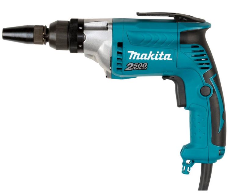
Explanation of general view
- Locator
- Front cap
- Switch trigger
- Lock button
- Lamp
- Reversing switch lever
- Adjusting ring
- Pointer
- Hook
- Bit
- Sleeve
SPECIFICATIONS
| Model | FS2700 | FS2701 | |
| Capacities |
Self drilling screw | 6 mm | |
| Machine screw | 8 mm | ||
| Wood screw | 6.2 mm | ||
| No load speed (min-1) | 0 – 2,500 | ||
| Overall length | 301 mm | 283 mm | |
| Net weight | 1.8 kg | 1.7 kg | |
| Safety class | /II | ||
- Due to our continuing programme of research and development, the specifications herein are subject to change without notice.
- Specifications may differ from country to country.
- Weight according to EPTA-Procedure 01/2003
Intended use
The tool is intended for screw driving in wood, metal and plastic.
Power supply
The tool should be connected only to a power supply of the same voltage as indicated on the nameplate, and can only be operated on single-phase AC supply. They are double-insulated in accordance with European Standard and can, therefore, also be used from sockets without earth wire.
For European countries only
Noise
The typical A-weighted noise level determined according to EN60745:
- Sound pressure level (L PA) : 83 dB(A)
- Sound power level (L WA) : 94 dB(A)
- Uncertainty (K) : 3 dB(A)
Wear ear protection
Vibration
The vibration total value (tri-axial vector sum) determined according to EN60745:
- Work mode: screwdriving without impact
- Vibration emission (ah) : 2.5 m/s2or less
- Uncertainty (K) : 1.5 m/s2
- The declared vibration emission value has been measured in accordance with the standard test method and may be used for comparing one tool with another.
- The declared vibration emission value may also be used in a preliminary assessment of exposure.

- The vibration emission during actual use of the power tool can differ from the declared emission value depending on the ways in which the tool is used.
- Be sure to identify safety measures to protect the operator that are based on an estimation of exposure in the actual conditions of use (taking account of all parts of the operating cycle such as the times when the tool is switched off and when it is running idle in addition to the trigger time).
EC Declaration of Conformity
We Makita Corporation as the responsible manufacturer declare that the following Makita machine(s):
- Designation of Machine: Screwdriver
- Model No./ Type: FS2700, FS2701 are of series production and
Conforms to the following European Directives:
98/37/EC until 28th December 2009 and then with 2006/42/EC from 29th December 2009 And are manufactured in accordance with the following standards or standardised documents: EN60745 The technical documentation is kept by our authorised representative in Europe who is:
- Makita International Europe Ltd,
- Michigan, Drive, Tongwell,
- Milton Keynes, MK15 8JD, England
30th January 2009
Tomoyasu Kato , Director Makita Corporation 3-11-8, Sumiyoshi-cho, Anjo, Aichi, JAPAN

General Power Tool Safety Warnings

SPECIFIC SAFETY RULES
DO NOT let comfort or familiarity with product (gained from repeated use) replace strict adherence to screwdriver safety rules. If you use this power tool unsafely or incorrectly, you can suffer serious personal injury.
- Hold power tool by insulated gripping surfaces, when performing an operation where the fastener may contact hidden wiring or its own cord. Fasteners contacting a “live” wire may make exposed metal parts of the power tool “live” and could give the operator an electric shock.
- Always be sure you have a firm footing. Be sure no one is below when using the tool in high locations.
- Hold the tool firmly.
- Keep hands away from rotating parts.
- Do not touch the bit or the workpiece immediately after operation; they may be extremely hot and could burn your skin.
SAVE THESE INSTRUCTIONS.
MISUSE or failure to follow the safety rules stated in this instruction manual may cause serious personal injury.
FUNCTIONAL DESCRIPTION
Always be sure that the tool is switched off and unplugged before adjusting or checking function on the tool.
Depth adjustment
For Model FS2700 only (Fig.1)

When you wish to drive self drilling screws, etc., adjust the depth as follows. Turn the locator to adjust the depth. Adjust the locator to create a distance of approximately 1 mm from the tip of the front cap (which works in conjunction with the locator) to the base of the screw head. One full turn of the locator equals 1 mm change in depth.
Fig.2 ,
Fig.3 ,Fig.4
Switch action
Before plugging in the tool, always check to see that the switch trigger actuates properly and returns to the “OFF” position when released. To start the tool, simply pull the switch trigger. Tool speed is increased by increasing pressure on the switch trigger. Release the switch trigger to stop. For continuous operation, pull the switch trigger and then push in the lock button. To stop the tool from the locked position, pull the switch trigger fully, then release it.


NOTE:
Even with the switch on and motor running, the bit will not rotate until you fit the point of the bit in the screw head and apply forward pressure to engage the clutch.
Lighting up the lamps
Fig.5
- Do not look in the light or see the source of light directly.
- To turn on the lamp, pull the trigger. Release the trigger to turn it off.
NOTE:
Use a dry cloth to wipe the dirt off the lens of lamp. Be careful not to scratch the lens of lamp, or it may lower the illumination.
Reversing switch action
Fig.6
Always check the direction of rotation before operation. Use the reversing switch only after the tool comes to a complete stop. Changing the direction of rotation before the tool stops may damage the tool. This tool has a reversing switch to change the direction of rotation. Move the reversing switch lever to the


Adjusting the fastening torque
When you wish to drive machine screws, wood screws, hex bolts, etc. with the predetermined torque, adjust the fastening torque as follows.
Fig.7
The fastening torque may be adjusted by turning the adjusting ring. The torque is increased by turning the adjusting ring in the direction of the arrow and decreased by turning it in the opposite direction. Align the number 1 on the adjusting ring with the pointer on the gear housing. Drive a trial screw into your material or a piece of duplicate material. If the fastening torque is not suitable for the screw, continue adjusting until the proper torque is obtained.

The adjusting ring should be turned only within the numbered range. It should not be forced beyond this range.
Hook
Fig.8

The hook is convenient for temporarily hanging the tool.
ASSEMBLY
Always be sure that the tool is switched off and unplugged before carrying out any work on the tool.
Installing or removing the bit
For Model FS2700
To remove the bit, first pull the front cap off and then pull the bit out firmly.
Fig.9
To install the bit, insert it into the tool as far as it will go and then replace the front cap.
For Model FS2701
To install the bit, pull the sleeve in the direction of the arrow and insert the bit into the sleeve as far as it will go. Then release the sleeve to secure the bit. Fig.10
To remove the bit, pull the sleeve in the direction of the arrow and pull the bit out firmly.

NOTE:
- If the bit is not inserted deep enough into the sleeve, the sleeve will not return to its original of position and the bit will not be secured. In this case, try re-inserting the bit according to the instructions above.
- After inserting the bit, make sure that it is firmly secured. If it comes out, do not use it.
OPERATION
Fig.11
Fig.12


Fit the screw on the point of the bit and place the point of the screw on the surface of the workpiece to be fastened. Apply pressure to the tool and start it. Withdraw the tool as soon as the clutch cuts in. Then release the switch trigger.

- When fitting the screw onto the point of the bit, be careful not to push in on the screw. If the screw is pushed in, the clutch will engage and the screw will rotate suddenly. This could damage a workpiece or cause an injury.
- Make sure that the bit is inserted straight in the screw head, or the screw and/or bit may be damaged.
MAINTENANCE
- Always be sure that the tool is switched off and unplugged before attempting to perform inspection or maintenance.
To maintain product SAFETY and RELIABILITY, repairs, carbon brush inspection and replacement, any other maintenance or adjustment should be performed by Makita Authorized Service Centers, always using Makita replacement parts.
ACCESSORIES
- These accessories or attachments are recommended for use with your Makita tool specified in this manual. The use of any other accessories or attachments might present a risk of injury to persons. Only use accessory or attachment for its stated purpose.
If you need any assistance for more details regarding these accessories, ask your local Makita Service Center.
- Phillips bit
- Magnetic socket bit
- Front cap