Honeywell VERTEXEDGE Vertex SF System User Manual

User Manual


Safety
Read this information before starting using your device.
About this Publication
While this information is presented in good faith and believed to be accurate, Honeywell disclaims the implied warranties of merchantability and fitness for a particular purpose and makes no express warranties except as may be stated in its written agreement with and for its customers.
In no event is Honeywell liable to anyone for any indirect, special, or consequential damages. The information and specifications in this document are subject to change without notice.
Trademarks
Brand or product names are trademarks of their respective owners. The following brand or product names are trademarks of Honeywell:
- Honeywell Vertex® SF
- Chemcassette®
General Safety
Follow all installation and operational instructions to ensure the safe and reliable operation of this unit. If this monitor is used in a manner not specified by Honeywell Analytics Inc., the protection provided by the equipment may be impaired.
EMC Considerations
Your Honeywell Analytics continuous gas monitor has been designed to comply with applicable Electromagnetic Compatibility (EMC) standards at the time of manufacture. The design includes filtering, shielding, and bypassing techniques. At the time of certification, simulated customer Input/ Output (I/O) schemes were tested.
All methods used in your equipment for emission suppression and reduction of susceptibility are interactive. Modifications to the monitor could result in increased emissions and higher vulnerability to other radiated fields.
Following the guidelines in this EMC Considerations section will ensure your monitor maintains the highest degree of EMC integrity. The guidelines listed apply only to I/O emissions and do not apply to A.C. and D.C. monitor power connections.
FCC Compliance Statement
CAUTION: Changes or modifications not expressly approved could void your authority to use this equipment.
This device complies with Part 15 of the FCC Rules. The operation to the following two conditions:
- This device may not cause harmful interference, and
- This device must accept any interference received, including interference that may cause undesired operation.
Industry Canada Statement
This device contains license-exempt transmitter(s)/receiver(s) that comply with Innovation, Science, and Economic Development Canada’s license-exempt RSS(s). Operation is subject to the following two conditions:
- This device may not cause interference.
- This device must accept any interference, including interference that may cause undesired operation of the device.
Cabling
At a very minimum, all cables should include a braided shield. Ideal results have been obtained with twisted-pair cabling which has a foil shield surrounding each pair plus foil and 90% braid shielding around the bundle. In addition, ensure local electrical code requirements are met.
The following cable parameters must be considered:
| Braid | Must have a minimum 90% coverage |
| Foil | When used with braid, provides 100% coverage. Do not use foil alone. It has a tendency to break. |
| Twisted Pair | Provides for canceling of magnetic fields |
| Stranded Pair | Provides the greatest surface area |
| Shield Termination | Continuation of the shield to the cabinet earth ground is most important. For discrete wire terminations, pigtails to the cabinet (connector) ground should be extremely short (absolutely no greater than three inches). For multiconductor connector terminations, only 360° shielded shells should be used. |
Note:
Honeywell Analytics product testing uses >90% braid with foil (around the bundle); twisted pair; stranded 24 AWG (minimum wiring for all qualification and certification testing.)
Connectors
All qualifications and certifications of Honeywell Analytics products were achieved with high-quality connectors, providing 360° shield coverage. These connectors generally had metal shells.
Failure to properly secure the connector to the equipment will result in high emission levels.
Also, poorly constructed or improperly assembled connectors can be a high source of radiated noise and provide a path for external signals into the monitor.
Introduction
Learn what you need to know about the Honeywell Vertex® SF Continuous Monitor System before operating.
System Overview
The Honeywell Analytics Vertex SF™ System continuously monitors for toxic gases. It responds to gases that exceed programmed levels by:
- Triggering alarms and opening event windows to warn operators of high or low concentrations
- Triggering relays to external devices
- Displaying the location, gas type, and gas concentration
- Storing the alarm information in a database
The Vertex SF System provides a fast response to a wide range of gases. Each location may be up to 400 ft (122 m) from the Vertex SF System. The system uses one or more of Honeywell Analytics’ Chemcassette® analyzers, with or without pyrolyzers, to provide a monitoring system tailored to meet the requirements of the facility. The Vertex SF System incorporates a range of redundant and protective features for maximum uptime:
- Intelligent analyzer modules allow one to stop monitoring with no effect on the remaining modules
- Power supplies are redundant
- The system powers up in the same state as when powered down
- Filters, Chemcassettes®, and major components in one of the analyzers can be replaced while the remaining analyzers continue to function.
The operation can be through an LCD touch screen or through a local area network (LAN).
Chemcassette® is a registered trademark of Honeywell Analytics, Inc.
System Components
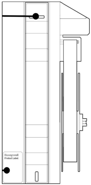
The following photos illustrate the Vertex SF System views, ports, connections, and controls.
Analyzer side panel — Exterior

Analyzer side panel — Interior

Analyzer — Front view

- Analyzer status LED
- Product label
Chemcassette Detection System
The Chemcassette® Analyzer module is a self-contained, microprocessor-controlled analyzer that occupies one slot in a Vertex tier. Sample lines and the vacuum source are connected to the Chemcassette® via a single 10-tube connector.
The system powers up in the same state as when powered down. Data is stored in the module’s memory until the data acquisition computer retrieves it.
The Vertex Analyzer modules use the Honeywell Analytics’ Chemcassette® optical detection system. Analyzer modules sample and detect a specific gas or family of gases.
- Each eight-point Analyzer module:
- Manages Chemcassette® tape transport
- Provides optical detection of stain
- Directs sample flow through the Chemcassette®
- Stores data for retrieval by the data acquisition computer
Components of the detection system include:
- Chemcassette® detection tape
- Optics and electronics for the detection system
- Chemcassette® tape transport mechanism
- Self-adjusting manual needle valve
Detector Optics
The heart of the Chemcassette® module is an optical detection system that measures a stain that develops on the Chemcassette® tape in the presence of a target gas. Each eight-point Analyzer module has two detection heads, each with four individual detectors.
Stain Pattern
The following chart shows the staining pattern of sample detection on the Chemcassette® tape.

When monitoring a location, the system detects and measures a specific gas or a family of gases in the sample. The microprocessor in the analyzer module interprets the data and responds appropriately.
In the Closed Loop Optics (CLO) detection system, a reference detector monitors and controls the intensity of the LED.

The microprocessor in the Chemcassette analyzer module interprets the stain. It then calculates and stores a precise concentration level in the module’s memory. Gas concentrations are reported in parts-per-million (ppm), parts-per-billion (ppb) or milligrams-per-cubic-meter (mg/m³ ).
Chemcassette® Tapes
Chemcassette® tapes are tagged with a radio frequency identification (RFID) tag to automatically identify the following:
- Serial number
- Gas family/ tape type
- Revision level
- The expiration date of the tape
- Chemcassette® leader parameters
The module uses a leader on the Chemcassette® tape to allow calibration of the optics every time a new tape is installed. This feature can be bypassed.
Install an Analyzer
- Reach into the slot and position cables out of the way.
- Place analyzer on slides. Push in until locks engage.
- Slide Analyzer out until fully extended.
- Reach behind the analyzer; connect and lock the tubing harness.
NOTE
When reconnecting the analyzer, connect the Analyzer Communications cable to the analyzer first. - Connect the Analyzer Communications, 24V Power Supply, and Multifunction Connector.
- Carefully push the analyzer partially into the cabinet and then pull out to verify all cables move freely and the slides lock. Repeat in and out action to loosen the slide. Push the analyzer into the cabinet.
Return to Service
- Turn the analyzer power switch on.
- Re-install the Configuration Profile.
- Install the Chemcassette.
- Return analyzer to monitor mode in Runtime Options Menu
Specifications
| Overall system dimension | |
| Size | 76″X24″X35″ |
| Weight – Full loaded condition | 1,000lbs (454kg) |
| Weight – Empty rack | ≤730lbs (331kg) |
| Analyzer | |
| Size | 22″ x 13″ x 6″ |
| Weight | ≤ 27lbs(12kg) |
| Power Requirements | |
| Operating Voltage | DC 24V / 2.5A |
| Power Consumption | |
| Normal condition | 1125 Watt |
| Maximum condition | <1400 Watt |
| Outputs | |
| Visual | 15.6″ widescreen monitor with capacitive touch interface Display gas reading, alarm & instrument status real-time base Provided real-time trend chart and gas event snapshot trend chart. Event logging including maintenance/instrument fault and gas alarm Multiple searching options for the event LED indicator: Normal (Green), Alarm 1 (Red), Alarm 2 (Red), Fault (Yellow) |
| Digital Communications | TCP/IP and RTU Modbus, OPC (Option) |
| Security | |
| Role-based access control Supports HTTPS | |
| Certification and Specification | |
| EN 50270 and EN61010-1 UL/IEC 61010-1 RED, FCC for RFID | |
| Performance | |
| Refer to the gas list table | |
| Transport System | |
| Flow Rate | 2.4 LPM |
| Transport Time | Less than 45 seconds up to 328ft with a thin wall tube (0.190″ID) Less than 40 seconds up to 400ft with a medium wall (0.156″ID) |
| Sample Line Tubing | 1/4 in. (6.35 mm)O.D. x 0.190 in. (4.83 mm) I.D. (Thin wall)FEP Teflon or 1/4 in. (6.35 mm) O.D. x 0.156 in. (3.9 mm) (Medium wall) |
| Tubing Length | Up to 328ft (100m) with a thin wall; Up to 400ft (122m) with a medium wall |
| Exhaust Line Tubing | 1/2 in. (12.7 mm) O.D. x 3/8 in. (9.5 mm) I.D. Teflon tubing, |
| Exhaust Length | Up to 50 ft. (15 m) maximum |
| Operating conditions | |
| Temperature | 59°F to 95°F (15°C to 35°C) |
| Humidity | 20-80% RH |
| Altitude | –1000 ft. (–305 m) to 6000 ft. (1829 m) above sea level |
| Pollution Degree | 2 |
| Wiring Requirement | |
| Power | Singe phase power, Minimum 14 AWG |
| Digital | CAT5 Cable or equivalent: RJ45 connector |