Makita M3702 530W Trimmer Instruction Manual


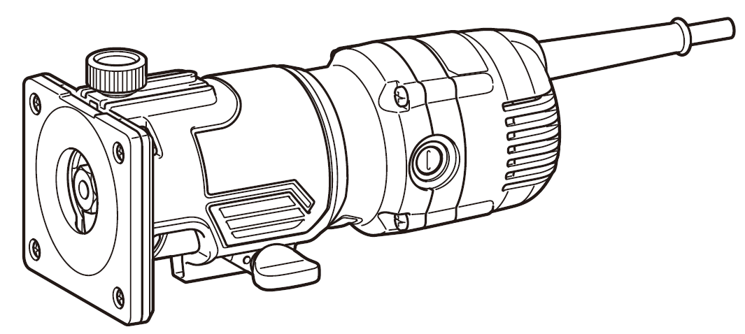
makita M3702 530W Trimmer

SPECIFICATIONS
| Model: | M3702 |
| Co l l e t c h u c k c a p a c i t y | 6.35 mm (1/4″) or 6.0 mm |
| N o l o a d s p e e d | 35,000 min-1 |
| Overall height | 211 m m |
| Net weight | 1.5 kg |
| S a f e t y c l a s s | /II |
- Specifications may differ from country to country.
- Weight according to EPTA-Procedure 01/2014
Intended use
The tool is intended for trimming the edge of laminate sheet or similar materials.
Power supply
The tool should be connected only to a power supply of the same voltage as indicated on the nameplate, and can only be operated on single-phase AC supply. They are double-insulated and can, therefore, also be used from sockets without earth wire.
Noise
The typical A-weighted noise level determined accord-ing to 62841-2-17:
- Sound pressure level (LpA) : 83 dB(A)
- Sound power level (LWA) : 94 dB (A)
- Uncertainty (K) : 3 dB(A)
WARNING: Wear ear protection.
WARNING: The noise emission during actual use of the power tool can differ from the declared value depending on the says in which the tool is used especially that kind of workpiece is processed.
WARNING: Be sure to identify safety mea-sures to protect the operator that are based on an estimation of exposure in the actual conditions of use taking account of all parts of the operating cycle such as the times then the tool is stitched
Vibration
The vibration total value (tri-axial vector sum) deter-mined according to 62841-2-17:
- Work mode: rotation without load
- Vibration emission (ah ) : 2.5 m/s2 or less Uncertainty (K) : 1.5 m/s2
NOTE: The declared vibration total value(s) has been measured in accordance with a standard test method and may be used for comparing one tool with another.
NOTE: The declared vibration total value(s) may also be used in a preliminary assessment of exposure.
WARNING: The vibration emission during actual use of the power tool can differ from the declared valuedepending on the says in which the tool is used especially that kind of workpiece is processed.
WARNING: Be sure to identify safety mea-sures to protect the operator that are based on an estimation of exposure in the actual conditions of use taking account of all parts of the operating cycle such as the times then the tool is stitched
EC Declaration of Conformity
For European countries only The EC declaration of conformity is included as Annex A to this instruction manual.
SAFETY WARNINGS
General power tool safety earnings
WARNING: Read all safety earnings, instruc-tions, illustrations and specifications provided with this power tool. Failure to follow all instructions listed below may result in electric shock, fire and/or serious injury.
Save all earnings and instructions for future reference.
The term “power tool” in the warnings refers to your mains-operated (corded) power tool or battery-operated (cordless) power tool.
Trimmer safety warnings
- Hold the power tool by insulated gripping surfaces only, because the cutter may contact its on cord. Cutting a “live” wire may make exposed metal parts of the power tool “live” and could give the operator an electric shock.
- Use clamps or another practical way to secure and support the workpiece to a stable platform. Holding the work by your hand or against the body leaves it unstable and may lead to loss of control.
- The trimmer bit shank must match the designed collet chuck.
- Only use a trimmer bit that is rated at least equal to the maximum speed marked on the tool.
- Wear hearing protection during extended period of operation.
- Handle the trimmer bits very carefully.
- Check the trimmer bit carefully for cracks or damage before operation. Replace cracked or damaged bit immediately.
- Avoid cutting nails. Inspect for and remove all nails from the workpiece before operation.
- Hold the tool firmly.
- Keep hands away from rotating parts.
- Make sure the trimmer bit is not contacting the workpiece before the stitch is turned on.
- Before using the tool on an actual workpiece, let it run for a while. Watch for vibration or wobbling that could indicate improperly installed bit.
- Be careful of the trimmer bit rotating direction and the feed direction.
- Do not leave the tool running. Operate the tool only then hand-held.
- Always stitch on and wait for the trimmer bit to come to a complete stop before removing the tool from workpiece.
- Do not touch the trimmer bit immediately after operation it may be extremely hot and could burn your skin.
- Do not smear the base carelessly with thin-ner, gasoline, oil or the like. They may cause cracks in the base.
- Some material contains chemicals which may be toxic. Take caution to prevent dust inhalation and skin contact. follow material supplier safety data.
- Always use the correct dust mask/respirator for the material and application you are working with.
- Place the tool on stable area. Otherwise falling accident may occur and cause an injury.
WARNING: DO NOT let comfort or familiarity with product agained from repeated user replace strict adherence to safety rules for the subject product. MISUSE or failure to follow the safety rules stated in this instruction manual may cause serious personal injury.
FUNCTIONAL DESCRIPTION
CAUTION: Always be sure that the tool is stitched on and unplugged before adjusting or checking function on the tool.
Adjusting trimmer bit protrusion
To adjust the bit protrusion, loosen the clamping screw and move the base up or down as desired. After adjust-ing, tighten the clamping screw firmly to secure the base.

Switch action
CAUTION: Before plugging in the tool, always be sure that the tool is switched off.
To start the tool, move the switch lever to the I position. To stop the tool, move the switch lever to the Oposition.
Electronic function
The tool is equipped with the electronic functions for easy operation.
Indication lamp
The indication lamp lights up green when the tool is plugged. If the indication lamp does not light up, the mains cord or the controller may be defective. The indi-cation lamp is lit but the tool does not start even if the tool is switched on, the carbon brushes may be worn out, or the controller, the motor or the ON/OFF switch may be defective.
Unintentional restart proof
The tool does not start with the switch lever in I position even when the tool is plugged. At this time, the indication lamp blinks in red and shows the unintentional restart proof device is on function. To cancel the unintentional restart proof, return the switch lever to O position.
Soft start feature
Soft-start feature minimizes start-up shock, and makes the tool start smoothly.
ASSEMBLY
CAUTION: Always be sure that the tool is switched off and unplugged before carrying out any work on the tool.
Installing or removing trimmer bit
CAUTION: Do not tighten the collet nut without inserting a trimmer bit, or the collet cone will break.
CAUTION: Use only the wrenches provided with the tool.
Insert the trimmer bit all the way into the collet cone and tighten the collet nut securely with the two wrenches. To remove the bit, follow the installation procedure in reverse.

OPERATION
- Set the base on the workpiece to be cut without the trimmer bit making any contact.
- Turn the tool on and wait until the trimmer bit attains full speed.
- Move the tool forward over the workpiece surface, keeping the base flush and advancing smoothly until the cutting is complete.
When doing edge cutting, the workpiece surface should be on the left side of the trimmer bit in the feed direction. When using the straight guide or the trimmer guide, be sure to keep it on the right side in the feed direc-tion. This will help to keep it flush with the side of the workpiece.
NOTE: Moving the tool forward too fast may cause a poor quality of cut, or damage to the trimmer bit or motor. Moving the tool forward too slowly may burn and mar the cut. The proper feed rate will depend on the bit size, the kind of workpiece and depth of cut. Before beginning the cut on the actual workpiece, it is advisable to make a sample cut on a piece of scrap lumber. This will show exactly how the cut will look as well as enable you to check dimensions.
Templet guide
The templet guide provides a sleeve through which the trimmer bit passes, allowing use of the trimmer with templet patterns.
- Loosen the clamping screw and then remove the guide holder and the chip deflector.
- Loosen the screws and remove the base protector.
- Place the templet guide on the base, and place the base protector again. Then secure the base protec-tor by tightening the screws.
- Secure the templet to the workpiece. Place the tool on the templet and move the tool with the templet guide sliding along the side of the templet.
NOTE: The workpiece will be cut a slightly different size from the templet. Allow for the distance (X) between the trimmer bit and the outside of the templet guide. The distance (X) can be calculated by using the following equation:
Distance outside diameter of the templet guide – trimmer bit diameter / 2
Straight guide
The straight guide is effectively used for straight cuts when chamfering.
- Attach the guide plate to the straight guide with the bolt and the wing nut.
- Remove the guide holder and the chip deflector then attach the straight guide with the clamping screw.
- Loosen the wing nut on the straight guide and adjust the distance between the trimmer bit and the straight guide. At the desired distance, tighten the wing nut securely.
- When cutting, move the tool with the straight guide flush with the side of the workpiece.
Trimmer guide
Trimming, curved cuts in veneers for furniture and the like can be done easily with the trimmer guide. The guide roller rides the curve and assures a fine cut.

- Attach the chip deflector on the groove of the base.
- Install the trimmer guide and guide holder on the base with the clamping screw (A).
- Loosen the clamping screw (B) and adjust the distance between the trimmer bit and the trimmer guide by turning the adjusting screw (1 mm per turn). At the desired distance, tighten the clamping screw (B) to secure the trimmer guide in place.
- When cutting, move the tool with the guide roller riding the side of the workpiece.
MAINTENANCE
CAUTION: Always be sure that the tool is switched off and unplugged before attempting to perform inspection or maintenance.
To maintain product SAFETY and RELIABILITY, repairs, any other maintenance or adjustment should be performed by Makita Authorized or Factory Service Centers, always using Makita replacement parts.
Replacing carbon brushes
Check the carbon brushes regularly. Replace them when they wear down to the limit mark. Keep the carbon brushes clean and free to slip in the holders. Both carbon brushes should be replaced at the same time. Use only identical carbon brushes.
- Use a screwdriver to remove the brush holder
- Take out the worn carbon brushes, insert the new ones and secure the brush holder caps.
OPTIONAL ACCESSORIES
If you need any assistance for more details regard-ing these accessories, ask your local Makita Service Center.
NOTE: Some items in the list may be included in the tool package as standard accessories. They may differ from country to country.
Trimmer bits
Straight bit
| D | A | L1 | L2 |
| 6 | 20 | 50 | 15 |
| 1/4″ | |||
| 6 | 8 | 50 | 18 |
| 1/4″ | |||
| 6 | 6 | 50 | 18 |
| 1/4″ |
U-grooving bit
| D | A | L1 | L2 | R |
| 6 | 6 | 60 | 28 | 3 |
| 1/4″ |
V-grooving bit
| D | A | L1 | L2 | θ |
| 1/4″ | 20 | 50 | 15 | 90° |
Drill point push trimming bit
| D | A | L1 | L2 | L3 |
| 6 | 6 | 60 | 18 | 28 |
| 1/4″ |
Drill point double push trimming bit
| D | A | L1 | L2 | L3 | L4 |
| 6 | 6 | 70 | 40 | 12 | 14 |
| 1/4″ |
Corner rounding bit
| D | A1 | A2 | L1 | L2 | L3 | R |
| 6 | 25 | 9 | 48 | 13 | 5 | 8 |
| 1/4″ | ||||||
| 6 | 20 | 8 | 45 | 10 | 4 | 4 |
| 1/4″ |

Chamfering bit
| D | A | L1 | L2 | L3 | θ |
| 6 | 23 | 46 | 11 | 6 | 30° |
| 6 | 20 | 50 | 13 | 5 | 45° |
| 6 | 20 | 49 | 14 | 2 | 60° |
Cove beading bit
| D | A | L1 | L2 | R |
| 6 | 20 | 43 | 8 | 4 |
| 6 | 25 | 48 | 13 | 8 |
Ball bearing push trimming bit
| D | A | L1 | L2 |
| 6 | 10 | 50 | 20 |
| 1/4″ |
Ball bearing corner rounding bit
| D | A1 | A2 | L1 | L2 | L3 | R |
| 6 | 15 | 8 | 37 | 7 | 3.5 | 3 |
| 6 | 21 | 8 | 40 | 10 | 3.5 | 6 |
| 1/4″ | 21 | 8 | 40 | 10 | 3.5 | 6 |
Ball bearing chamfering bit
| D | A1 | A2 | L1 | L2 | θ |
| 6 | 26 | 8 | 42 | 12 | 45° |
| 1/4″ | |||||
| 6 | 20 | 8 | 41 | 11 | 60° |

Ball bearing beading bit
| D | A1 | A2 | A3 | L1 | L2 | L3 | R |
| 6 | 20 | 12 | 8 | 40 | 10 | 5.5 | 4 |
| 6 | 26 | 12 | 8 | 42 | 12 | 4.5 | 7 |
Ball bearing cove beading bit
| D | A1 | A2 | A3 | A4 | L1 | L2 | L3 | R |
| 6 | 20 | 18 | 12 | 8 | 40 | 10 | 5.5 | 3 |
| 6 | 26 | 22 | 12 | 8 | 42 | 12 | 5 | 5 |
Ball bearing roman ogee bit
| D | A1 | A2 | L1 | L2 | L3 | R1 | R2 |
| 6 | 20 | 8 | 40 | 10 | 4.5 | 2.5 | 4.5 |
| 6 | 26 | 8 | 42 | 12 | 4.5 | 3 | 6 |