SIEMENS RF300 SIMATIC HF RFID Systems User Manual


SIEMENS RF300 SIMATIC HF RFID Systems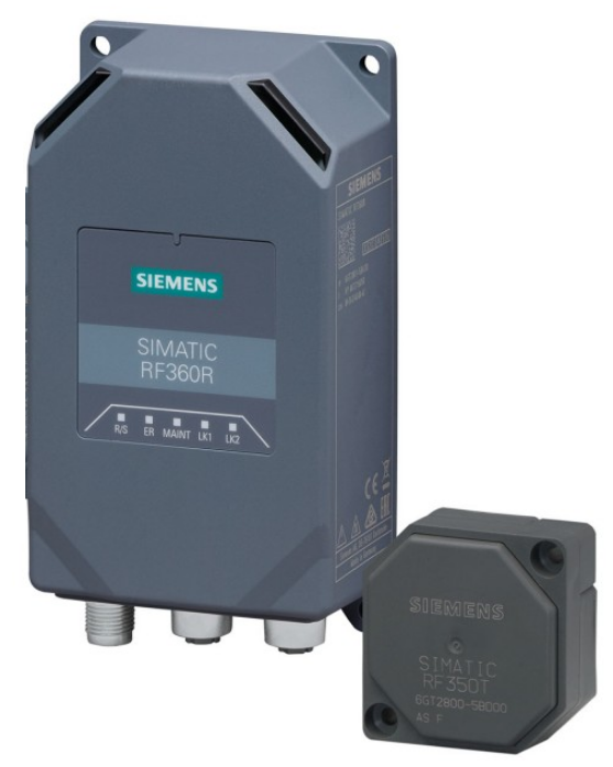

Legal information
Warning notice system
This manual contains notices you have to observe in order to ensure your personal safety, as well as to prevent damage to property. The notices referring to your personal safety are highlighted in the manual by a safety alert symbol, notices referring only to property damage have no safety alert symbol. These notices shown below are graded according to the degree of danger.
DANGER: indicates that death or severe personal injury will result if proper precautions are not taken.
WARNING: indicates that death or severe personal injury may result if proper precautions are not taken.
CAUTION indicates that minor personal injury can result if proper precautions are not taken.
NOTICE: indicates that property damage can result if proper precautions are not taken.
If more than one degree of danger is present, the warning notice representing the highest degree of danger will be used. A notice warning of injury to persons with a safety alert symbol may also include a warning relating to property damage.
Qualified Personnel
The product/system described in this documentation may be operated only by personnel qualified for the specific task in accordance with the relevant documentation, in particular, its warning notices and safety instructions. Qualified personnel are those who, based on their training and experience, are capable of identifying risks and avoiding potential hazards when working with these products/systems.
Proper use of Siemens products
Note the following
WARNING
Siemens products may only be used for the applications described in the catalog and in the relevant technical documentation. If products and components from other manufacturers are used, these must be recommended or approved by Siemens. Proper transport, storage, installation, assembly, commissioning, operation, and maintenance are required to ensure that the products operate safely and without any problems. The permissible ambient conditions must be complied with. The information in the relevant documentation must be observed.
Trademarks
All names identified by ® are registered trademarks of Siemens AG. The remaining trademarks in this publication may be trademarks whose use by third parties for their own purposes could violate the rights of the owner.
Disclaimer of Liability
We have reviewed the contents of this publication to ensure consistency with the hardware and software described. Since variance cannot be precluded entirely, we cannot guarantee full consistency. However, the information in this publication is reviewed regularly and any necessary corrections are included in subsequent editions.
SIMATIC RF360R
Features
| SIMATIC RF360R | Characteristics | |||
| Design | ① Status LEDs (status display of the reader and PROFINET connection) ② Operation LEDs (operating states of the reader) ③ Interface for the power supply X80 (M12, 4-pin, L-coded) ④ Interface for PROFINET IO X1 P1R (M12, 4-pin, D-coded) ⑤ Interface for PROFINET IO X1 P2R (M12, 4-pin, D-coded) 1) ⑥ Borehole for functional ground | |||
| Area of application | Identification tasks on assembly lines or AGV in industrial environments | |||
|
|
|
|||

- You can loop the PROFINET IO via the M12 round socket ⑤.
Note
Configuration Manual SIMATIC RF360R
- You can find a detailed description of the commissioning and configuration of the reader in the “SIMATIC RF360R (https://support.industry.siemens.com/cs/ww/en/ps/26319/man)” configuration manual.
Ordering data
RF360R ordering data
| Article number | |
| RF360R with RS-422 interface (3964R) | 6GT2801-5BA30 |
Connecting the reader to the functional ground
- You need to connect the reader to functional ground. A ground borehole is provided for this on the connection side of the reader for attaching a grounding conductor.
Required tools
You need the following tools to connect to the functional ground:
- Screwdriver
- Stripping tool
- Crimp tool
Accessories required
You need the following accessories to connect to the functional ground:
- Fastening screw (M3) and washer
- Cable lug suitable for M3 screws
- Ground conductor cable (copper braid) with a minimum cross-section of 4 mm2
Mounting
Proceed as follows to connect the reader to functional ground via a grounding conductor:
- Fasten the reader in the holes provided for this purpose.
- Insulate the ground conductor.
- Attach the cable lug to the ground conductor.
- Screw the cable lug together with the M3 fastening screws with a torque of 1.2 Nm.
NOTICE
Low-impedance connection
- Ensure a low impedance connection between the reader module and the functional ground.
- When attaching the grounding cable, ensure it is not on a coated surface.

Connecting readers
Requirement
- Only wire the communication module when the supply voltage is switched off.
Required tools
When using preassembled cables, you need the following tool:
- Torque wrench set (e.g. from Peres; M12/M8, can be set; PER091) for wiring the reader connections.
Note
Using pre-assembled cables
- When connecting the supply voltage, we recommend the cables specified in the section “AUTOHOTSPOT” (4 x 1.5 mm2 preassembled).
- If you want to make the cable yourself, ensure that the conductor cross-section matches the system setup or the corresponding protection (1.5 mm2).
- When using cables that are not preassembled, you need the tool for the specific cable/connector, for example, an insulation stripper, screwdriver or Allen wrench.
Accessories required
You need the following accessories:
- For connecting the power supply
- M12 plug (4-pin, L-coded) and 4-wire cable (4 x 1.5 mm2)
- for PROFINET IO connection
- M12 plug (4-pin, D-coded) and 4-wire Ethernet cable (Twisted Pair, shielded)
- You can find the associated article numbers in the section “AUTOHOTSPOT”.
Connect the plug
Proceed as follows to connect the device:
- Push the respective plug into the corresponding round socket on the reader.
- Make sure the connectors and sockets are properly interlocked (tongue and groove).
- Fasten the connector by tightening the knurled locking ring.
- To guarantee the degree of protection, you must fasten all connectors with ≃ 1.0 Nm.
NOTICE
Ensuring the degree of protection
- You need to close all unused sockets with M12 sealing caps to ensure IP65 or IP67 degrees of protection.
- You can find the order data of the sealing caps in the section “AUTOHOTSPOT”.
Pin assignment of the interfaces
The following tables show the pin assignment for the interfaces/connectors.
Pin assignment power supply; M12 socket (4-pin, L-coded)
| Pin | Assignment | View of M12 socket, 4-pin |
| 1 | +24 V (brown) | |
| 2 | Unassigned (white) | |
| 3 | Ground/shield (blue) | |
| 4 | Reset to Factory (black) |

Pin assignment PROFINET IO; M12 socket (4-pin, D-coded)
| Pin | Assignment | View of M12 socket, 4-pin |
| 1 | Data line TxP | |
| 2 | Data line RxP | |
| 3 | Data line TxN | |
| 4 | Data line RxN |
LED displays
Operation LED display
The operational states of the reader are displayed by two LEDs. The LEDs can adopt the colors white green, red, yellow, or blue, and the states off, on, flashing:
Shows the operating states via the operation LED display
| LEDs | Meaning |
| The reader is turned off. | |
| The reader is turned on and is searching for transponders. The reader is in the “Setup” mode, in the “Search for transponders” status, and has not yet received a “RESET” command, and is not ready. | |
|
There is a transponder in the antenna field. The reader is in the “Setup” mode, in the status “Show quality”, has not yet received a “RESET” command, and is not ready. Depending on the signal strength, the LED flickers or is lit permanently. |
| The reader has received a “RESET” command. | |
| The reader is turned on, the antenna is turned off. | |
| |
| There is an error. The number of flashes provides information about the current error. You can find more information on error messages in the section “AUTOHOTSPOT”. |


Status LED display (including PROFINET/Ethernet LEDs)
The operating states of the reader are displayed by the LEDs “R/S”, “ER”, and “MAINT”. The LEDs can adopt the colors green, red or yellow, and the statuses off, on, and flashing :
Shows the operating status via the status LED display

The states of the PROFINET/Ethernet connections are indicated by the “LK1” LEDs for interface “X1 P1R” and “LK2” for interface “X1 P2R”. The LEDs can adopt the colors green, red or yellow and the states off , on , flashing:
Shows the PROFINET/Ethernet states via the PROFINET/Ethernet LED display
| LK* | Meaning |
| |
| The flash test is performed for reader identification. At the same time, the LEDs of the operation and status LED on the display also flash. | |
|
Ensuring reliable data exchange
- The “center point” of the transponder must be situated within the transmission window.
Metal-free area
- The RF360R can be flush-mounted in metal. Allow for a possible reduction in the field data. To avoid any influence on the field data, the distance “a” should be kept to.

The minimum distance between several RF360R readers
RF360R side-by-side

- D ≥ ≥ 350 mm (with 2 readers)
- ≥ 500 mm (with more than 2 readers)
- Figure: 1-3 Minimum distance between several RF360R readers
RF360R face-to-face

- D ≥ 500 mm
- Figure: 1-4 Face-to-face distance between two RF360R
Technical specifications
Technical specifications of the RF360R reader


Approvals
FCC information
Siemens SIMATIC RF360R (MLFB 6GT2801-5BA30); FCC ID NXW-RF360R
This device complies with part 15 of the FCC rules. Operation is subject to the following two conditions:
- This device may not cause harmful interference.
- this device must accept any interference received, including interference that may cause undesired operation.
Caution: Any changes or modifications not expressly approved by the party responsible for compliance could void the user’s authority to operate the equipment.
Note
This equipment has been tested and found to comply with the limits for a Class A digital device, pursuant to part 15 of the FCC Rules. These limits are designed to provide reasonable protection against harmful interference when the equipment is operated in a commercial environment. This equipment generates, uses, and can radiate radio frequency energy and, if not installed and used in accordance with the instruction manual, may cause harmful interference to radio communications. Operation of this equipment in a residential area is likely to cause harmful interference in which case the user will be required to correct the interference at his own expense.
IC information
This device complies with Industry Canada licence-exempt RSS standard(s). Operation is subject to the following two conditions:
- This device may not cause interference.
- this device must accept any interference, including interference that may cause undesired operation of the device.
UL information (IEC 61010-1 / IEC 61010-2-201)
This standard applies to equipment designed to be safe at least under the following conditions:
- indoor use;
- altitude up to 2 000 m;
- temperature -0 °C to 55 °C;
- maximum relative humidity 80 % for temperature up to 31 °C decreasing linearly to 50 % relative humidity at 40 °C;
- TRANSIENT OVERVALTAGES up to the levels of OVERVOLTAGE CATEGORY II,
NOTE 1: These levels of transient overvoltage are typical for equipment supplied from the building wiring.
- using an “NEC Class 2” power supply is required
- the device is categorized as pollution degree 3/4
