Bosch RF3405E Wireless Inertia Instruction Manual


BOSCH RF3405E Wireless Inertia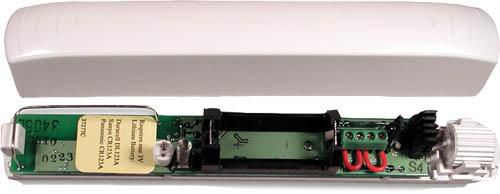

General Information
The inertia transmitter is equipped with internal reed contacts for use with an external magnet as-sembly and an inertia sensor for detecting shock. The transmitter can accept a dual EOL resistor supervised dry contact input from an external device. A supervisory signal is transmitted every 13min to supervise the device if there is no other activity. All transmissions from the RF3405E send battery status information.
Mounting
Mounting Considerations
The maximum range in the open is ≃ 300m (98 ft.). Keep the transmitter within 100m (328ft.) of the receiver to which it is assigned. Mounting the inertia transmitter on metal surfaces may reduce the RF range. Mounting it on ferrous metal (iron or steel) may affect the operation of the internal magnetic contact. Mount the inertia transmitter on the door or window frame. Mount the magnet assembly on the moving portion.
Notice
The magnet assembly must be oriented as shown in Figure 1. The magnet must be farther away than 10mm (0.39in) from the body of the inertia sensor for normal operation.
Mounting the Transmitter
- Position the base plate over the wanted location. If connecting to external contacts, position the mounting plate so the wiring passes through the wire entrance (callout #5).
- If the transmitter is installed, remove the inertia sensor bracket by pressing the inertia sensor tab(callout #1).
- Remove the circuit board by pressing the circuit board tab (callout #2).
- Mount the base plate using the 13 mm (0.51 in.) pan head screws (callout #3) through the base mounting holes (callout #4).
- Refer to Section 2.4 Mounting the Inertia Sensor if the inertial sensor is used

1 – Inertia transmitter
2 – Magnet
3 -Cover screw location

- Inertia sensor bracket
- Circuit board tab
- 13 mm (0.51 in.) pan head mounting screws
- Base mounting holes
- Wire entrance
Mounting the Magnet (if used)
Position the magnet base plate over the wanted location, using the mounting configuration.

- Magnet assembly
- 16 mm (0.63 in.) flathead screws
- Magnet assembly mounting holes
Mounting the Inertia Sensor
- Mount the inertia sensor so the wires are over the notched portion of the base plate.
- Press the inertia sensor into the bracket.
- It is possible to mount the inertia sensor in four different positions on the base plate. Route the wiring in a way that prevents crimping by the cover.

1 – Inertia sensor
2 – Notch in the base bracket
3 – Inertia sensor base bracket

Notice
Orientation of the Inertia sensor is critical to the proper operation of the inertia detection function. A UP arrow, imprinted on the body of this sensor, must always point upwards when mounted in the transmitter base.
Wiring
Notice
The RF3405E can be wired for an inertia sensor or an external contact, but not both.
Wiring for Inertia Sensor

- Inertia sensor wires
- Wire jumper across loop terminals
Wiring for the External Contact
- Wire jumper across inertia terminals
- The length of the contact loop can be up to 6 m (20 ft.)
- Normally closed (NC) contact
Notice
The wire jumper in the Loop terminals must be ON when using the Inertia function. The wire jumper in the Inertia terminals must be ON when using the External contact function.
Jumper Settings
Reed Switch Enable (Jumper P2)
If Jumper P2 is removed, the internal magnetic reed switches are enabled.

- Jumper on disables internal reed switches
- No jumper enables internal reed switches
Setting for Inertia or External Contact (Jumper P6) The detector can be set to monitor the internal inertia sensor or a set of external contacts.
- External contact
- Inertia sensor
Minor and Gross Attack (Jumper P1)
If Jumper P1 is installed, the inertia detector reacts only to Gross Attacks (major movement). Minor movement does not activate the inertia detector. Jumper P4 and Jumper P5 settings determine the sensitivity of the inertia detector to Gross Attack. Jumper P6 must be set for Inertia to enable it.

- Wire jumper across inertia terminals
- Length of contact loop can be up to 6 m (20 ft.) 3 – Normally closed (NC) contact
Pulses for Minor Attack (Jumper P3)
The setting of Jumper P3 determines the number of repetitive pulses needed to activate the inertia detector to a Minor Attack. If Jumper P3 is removed, the inertia detector reacts to four repetitive pulses. This setting is valid if Jumper P1 is set for Minor At-tack and Jumper P6 is set for Inertia.

- Jumper on for eight repetitive pulses
- No jumper for four repetitive pulses
Sensitivity for Gross Attack (Jumpers P4 and P5) These settings are valid only if Jumper P6 is set for Inertia.

- Low sensitivity
- Low/Medium sensitivity
- Medium/High sensitivity
- High sensitivity
Installing the Battery
Check the battery polarity.

Programming the Panel
A two-part ID sticker is located on the housing of the RF3405E. The number is needed to program the inertia transmitter into the control panel. Refer to the panel Programming Guide for programming information on wireless-type devices.
Testing the Detector
When the detector is mounted place it in Test Mode for 15 min. Open and Close the detector cover or push both tamper springs and release one or both (if the cover is off). The LED flashed once (continuing to flash dimly) if it is in Test Mode. During the test, the LED flashes twice each time a Minor Inertia Attack occurs, and a magnetic contact changes the state (open or closes), or any time the external contact (if used) changes state. The LED flashes three times for a Gross Inertia Attack. If any jumper is changed during Test Mode, the LED flashes once.
Specifications
| Dimensions (H x W x D) | Transmitter: 2.7 cm x 2.4 cm x 16.9 cm (1.06 in x 0.94 in. x 6.65 in.) Magnet: 1.9 cm x 1.3 cm x 16.9 cm (0.75 in. x 0.51 in. x 2.36 in.) |
| Operating Temperature | -20 °C to +60 °C (-4 °F to +151 °F); 0% to 95% relative humidity (non-condensing) |
| Frequency Band | 433.42 MHz |
| Maximum RF Power | Less than 10 mW |
| Operating Voltage | Supplied by a 3 VDC lithium battery |
| Battery Life | A minimum of 3 years under normal operating conditions with recommended battery types (2 years if using the inertia sensor). |
| Recommend Battery Types | Duracell DL123A / Energizer EL123AP / Panasonic CR123A |
| Compatible Receiver | RF3227E |
| Supervisory Internal | 13 minutes nominal |
FCC STATMENT
T3X-RF05 Changes or modifications not expressly approved by the manufacturer could void the user’s authority to operate the equipment. This device complies with part 15 of the FCC Rules. Operation is subject to the following two conditions:(1) This device may not cause harmful interference, and (2) this device must accept any interference re-ceived, including interference that may cause undesired operation. This equipment has been tested and found to comply with the limits for a Class B digital device, pursuant to part 15 of the FCC Rules. These limits are designed to provide reasonable protection against harmful interference in a residential installation. This equipment generates, uses, and can radiate ra-dio frequency energy and, if not installed and used in accordance with the instructions, may cause harmful interference to radio communications. However, there is no guarantee that interference will not occur in a particular installation. If this equipment does cause harmful interference to radio or television reception, which can be determined by turning the equipment off and on, the user is encouraged to try to correct the interference by one or more of the following measures: Reorient or relocate the receiving antenna. Increase the separation between the equipment and receiver. Connect the equipment into an outlet on a circuit different from that to which the receiver is connec-ted. Consult the dealer or an experienced radio/TV technician for help. IC 1249A-RF05 ISED This device contains license-exempt transmitter(s)/receiver(s) that comply with Innovation, Science, and Economic Development Canada’s license-exempt RSS(s). Operation is subject to the following two conditions:
- This device may not cause interference.
- This device must accept any interference, including interference that may cause undesired operation of the device.