Makita HP1631 Hammer Drill Instruction Manual


Hammer Drill
Instruction Manual


SPECIFICATIONS
| Model: | HP1630 | HP1631 | ||
| Capacities | Concrete | 16 mm | ||
| Steel | 13 mm | |||
| Wood | 30 mm | |||
| No-load speed | 0 – 3,200 min”‘ | |||
| Blows per minute | 0 – 48,000 min’ | |||
| Overall length | 296 mm | 295 mm | ||
| Net weight | 2.1 kg | 2.0 kg | ||
| Safety class | ||||

- Due to our continuing program of research and development, the specifications herein are subject to change without notice.
- Specifications may differ from country to country.
- Weight according to EPTA-Procedure 01/2014
Intended use
The tool is intended for impact drilling in brick, concrete, and stone as well as for drilling without impact in wood, metal, ceramic, and plastic.
Power supply
The tool should be connected only to a power supply of the same voltage as indicated on the nameplate, and can only be operated on a single-phase AC supply. They are double-insulated and can, therefore, also be used from sockets without earth wire.
Noise
The typical A-weighted noise level determined accoring to EN62841-2-1:
Sound pressure level (LpA) : 97 dB(A)
Sound power level (LWA) : 108 dB (A)
Uncertainty (K) : 3 dB(A)
NOTE: The declared noise emission value(s) has been measured in accordance with a standard test method and may be used for comparing one tool with another.
NOTE: The declared noise emission value(s) may also be used in a preliminary assessment of exposure.

Vibration
The vibration total value (tri-axial vector sum) deter
mined according to EN62841-2-1:
Work mode: impact drilling into concrete
Vibration emission (ah,ID) : 17.4 m/s
Uncertainty (K) : 1.5 m/s
Work mode: drilling into metal
Vibration emission (ah,D) : 2.5 m/s 2 or less
Uncertainty (K) : 1.5 m/s 2
NOTE: The declared vibration total value(s) has been measured in accordance with a standard test method and may be used for comparing one tool with another.
NOTE: The declared vibration total value(s) may also be used in a preliminary assessment of exposure.
EC Declaration of Conformity
For European countries, only
The EC declaration of conformity is included as Annex A to this instruction manual.
General power tool safety warnings
Save all warnings and instructions for future reference.
The term “power tool” in the warnings refers to your mains-operated (corded) power tool or battery-operated (cordless) power tool.
Hammer drill safety warnings
Safety instructions for all operations
- Wear ear protectors when impact drilling. Exposure to noise can cause hearing loss.
- Use the auxiliary handle(s). Loss of control can cause personal injury.
- Hold the power tool by insulated gripping surfaces, when performing an operation where the cutting accessory may contact hidden wiring or its own cord. Cutting accessory contacting a “live” wire may make exposed metal parts of the power tool “live” and could give the operator an electric shock.
- Always be sure you have a firm footing. Be sure no one is below when using the tool in high locations.
- Hold the tool firmly with both hands.
- Keep hands away from rotating parts.
- Do not leave the tool running. Operate the tool only when hand-held.
- Do not touch the drill bit or the workpiece immediately after operation; they may be extremely hot and could burn your skin.
- Some material contains chemicals that may be toxic. Take caution to prevent dust inhalation and skin contact. Follow material supplier safety data.
- If the drill bit cannot be loosened even if you open the jaws, use pliers to pull it out. In such a case, pulling out the drill bit by hand may result in injury by its sharp edge.
Safety instructions when using long drill bits
- Never operate at a higher speed than the maximum speed rating of the drill bit. At higher speeds, the bit is likely to bend if allowed to rotate freely without contacting the workpiece, resulting in personal injury.
- Always start drilling at low speed and with the bit tip in contact with the workpiece. At higher speeds, the bit is likely to bend if allowed to rotate freely without contacting the workpiece, resulting in personal injury.
- Apply pressure only in direct line with the bit and do not apply excessive pressure. Bits can bend causing breakage or loss of control, resulting in personal injury.
SAVE THESE INSTRUCTIONS
FUNCTIONAL DESCRIPTION
Switch action
► Fig.1: 1. Switch trigger 2. Lock button
To start the tool, simply pull the switch trigger. Tool speed is increased by increasing pressure on the switch trigger. Release the switch trigger to stop. For continuous operation, pull the switch trigger, push in the lock button and then release the switch trigger. To stop the tool from the locked position, pull the switch trigger fully, then release it
Reversing switch action
► Fig.2: 1. Reversing switch lever This tool has a reversing switch to change the direction of rotation. Move the reversing switch lever to the position ⇐(A side) for clockwise rotation or to the position⇒ (B side) for counterclockwise rotation.
Selecting the action mode
► Fig.3: 1. Action mode changing lever This tool has an action mode changing lever. For rotation with hammering, slide the action mode changing lever to the right(


ASSEMBLY
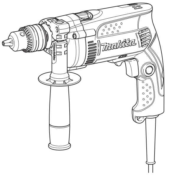
Installing side grip (auxiliary handle)
► Fig.4:
- Grip base
- Teeth
- Side grip (auxiliary handle)
- Protrusion
- Loosen
- Tighten
Always use the side grip to ensure operating safety. Install the side grip so that the teeth on the grip fit in between the protrusions on the tool barrel. Then tighten the grip by turning clockwise at the desired position. It may be swung 360° so as to be secured at any position.
Installing or removing the drill bit
For model HP1630
► Fig.5: 1. Drill chuck 2. Chuck key
To install the drill bit, place it in the drill chuck as far as it will go. Tighten the chuck by hand. Place the chuck key in each of the three holes and tighten clockwise. Be sure to tighten all three chuck holes evenly. To remove the drill bit, turn the drill chuck key counterclockwise in just one hole, then loosen the chuck by hand.
For model HP1631
► Fig.6: 1. Sleeve 2. Ring
Hold the ring and turn the sleeve counterclockwise to open the chuck jaws. Place the drill bit in the drill chuck as far as it will go. Hold the ring firmly and turn the sleeve clockwise to tighten the chuck. To remove the drill bit, hold the ring and turn the sleeve counterclockwise.
Depth gauge
Optional accessory
► Fig.7: 1. Depth gauge 2. Side grip 3. Grip base The depth gauge is convenient for drilling holes of uniform depth. Loosen the side grip and insert the depth gauge into the ole in the grip base. Adjust the depth gauge to the desired depth and tighten the side grip firmly.
NOTE: Make sure that the depth gauge does not touch the main body of the tool when attaching it.
OPERATION
► Fig.8
Hammer drilling operation
When drilling in concrete, granite, tile, etc., move the action mode changing lever to the position of the symbol to use the “rotation with hammering” action. Be sure to use a tungsten-carbide-tipped drill bit. Position the drill bit at the desired location for the hole, then pull the switch trigger. Do not force the tool. Light pressure gives the best results. eep, the tool in position and prevent it from slipping away from the hole. Do not apply more pressure when the hole becomes clogged with chips or particles. Instead, run the tool at an idle, then remove the drill bit partially from the hole. By repeating this several times, the hole will be cleaned out and normal drilling may be resumed.
Blow-out bulb
Optional accessory
► Fig.9: 1. Blow-out bulb After drilling the hole, use the blow-out bulb to clean the dust out of the hole.
Drilling operation
when drilling in wood, metal, or plastic materials, slide the action mode changing lever to the position of
Drilling in wood
When drilling in wood, the best results are obtained with wood drills equipped with a guide screw. The guide screw makes drilling easier by pulling the drill bit into the workpiece.
Drilling in metal
To prevent the drill bit from slipping when starting a hole, make an indentation with a center punch and hammer at the point to be drilled. Place the point of the drill bit in the indentation and start drilling. Use a cutting lubricant when drilling metals. The exceptions are iron and brass which should be drilled dry.
MAINTENANCE
NOTICE: Never use gasoline, benzene, thinner, alcohol, or the like. Discoloration, deformation, or cracks may result.
To maintain product SAFETY and RELIABILITY, repairs, carbon brush inspection, and replacement, any other maintenance or adjustment should be performed by Makita Authorized or Factory Service Centers, always using Makita replacement parts.
OPTIONAL ACCESSORIES
If you need any assistance with more details regarding these accessories, ask your local Makita Service Center.
- Drill bits
- Blow-out bulb
- Safety goggles
- Keyless drill chuck 13
- Chuck key
- Grip assembly
- Depth gauge
NOTE: Some items in the list may be included in the tool package as standard accessories. They may differ from country to country.
Makita Europe N.V.
Jan-Baptist Vinkstraat 2,
3070 Kortenberg, Belgium
Makita Corporation
3-11-8, Sumiyoshi-cho,
Anjo, Aichi 446-8502 Japan
www.makita.com
884816D996
EN, FR, DE, IT, NL,
ES, PT, DA, EL, TR
20200313