Panasonic WV-BWC4000 Body Worn Camera User Manual


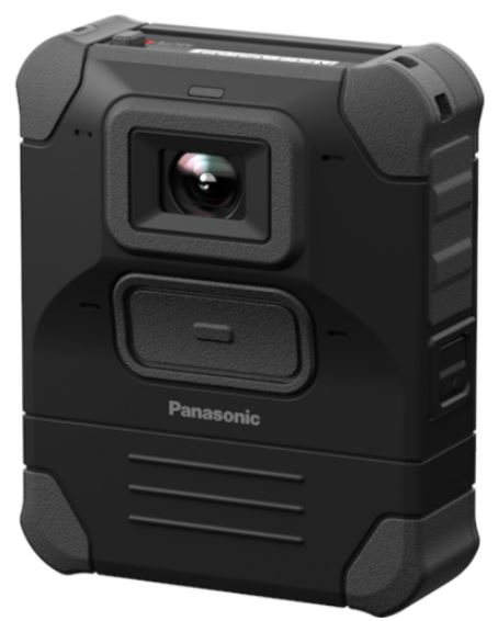
Panasonic WV-BWC4000 Body Worn Camera

Battery
WARNING:
- When Using the Battery
- Do not dismantle, open, crush, modify, shred or incinerate secondary batteries.
Do not subject batteries to mechanical shock. - Do not short-circuit a battery.
- In the event of a cell leaking, do not allow the liquid to come in contact with the skin or eyes. If contact has been made, wash the affected area with copious amounts of water and seek medical advice.
- Immediately discontinue use of the battery if, while using, charging, or storing the battery, the battery is giving out an unusual smell, feels hot, changes color, changes shape or appears abnormal in any other way.
- Keep batteries out of the reach of children.
- Do not dismantle, open, crush, modify, shred or incinerate secondary batteries.
- In storage
Do not expose the battery to heat or fire. Avoid storing the battery in a place exposed to direct sunlight, exposed to high temperatures such as in a vehicle under direct sunlight or in an area of low atmospheric pressure such as a highland. The temperature range over which the battery can be stored is –20 °C to +20 °C {–4 °F to +68 °F}
(Storage period:12 months). - While Charging
- Do not use any charger other than that specifically provided for use with the equipment.
- The temperature range over which the battery can be charged is 0 °C to 50 °C {32 °F to 122 °F}. Charging the battery at temperatures outside of this range may cause the battery to become hot or to break.
- Battery Replacement
Risk of explosion if battery is replaced by an incorrect type. - When Discharging the Battery
The temperature range over which the battery can be discharged is –20°C to 50°C {–4°F to 122°F}. Using the battery outside of this temperature range may also harm the performance of the battery or reduce the battery’s life expectancy. - Safe Disposal of Lithium Ion/Polymer Battery
Dispose of used Battery Pack according to local ordinances and/or regulations.
Environment & recycling
<WV-BWC4000>
A lithium-ion/polymer battery that is recyclable powers the product you have purchased.
Please call 1-800-8-BATTERY for information on how to recycle this battery.
<WV-BWC4000E>
Disposal of Old Equipment and Batteries
Only for European Union and countries with recycling systems
These symbols on the products, packaging, and/or accompanying documents mean that used electrical and electronic products and batteries must not be mixed with general household waste.
For proper treatment, recovery and recycling of old products and used batteries, please take them to applicable collection points in accordance with your national legislation. By disposing of them correctly, you will help to save valuable resources and prevent any potential negative effects on human health and the environment.
For more information about collection and recycling, please contact your local authority. Penalties may be applicable for incorrect disposal of this waste, in accordance with national legislation.
Note for the battery symbol (bottom symbol)
This symbol might be used in combination with a chemical symbol. In this case it complies with the requirement set by the Directive for the chemical involved.
Security alert when using Wireless LAN products
Wireless LAN provides with the advantage of freely connecting to the network as long as you are in the reach of radio waves.
On the other hand, the radio wave reaches everywhere in the range regardless of obstacles such as walls. Therefore, if security measure is not taken, the following problems may occur:
Communication content may be compromised A malicious third party may attempt to intercept the radio wave and steal your ID, password, transmitting images, etc.
Breaking into a system
A malicious third party may access your network without authorization and attempt the following:
- Stealing personal and confidential information (Information leakage)
- Impersonating a specific user, communicating and spreading false information (Impersonation)
- Re-writing the intercepted communication content (Falsification)
- Sending computer viruses to corrupt data or the system (Corruption)
In general, Wireless LAN is equipped with security-related functions to avoid the above threats. Therefore, enabling the security functions will reduce the possibility of occurrence of the above.
In order to reduce the occurrence of the security problem, make sure to set up the security-relating functions before using the Wireless LAN product.
Due to the specification of Wireless LAN, note that there is a possibility of the security function being compromised by a special manner.
In regard to the security-related settings, please contact your dealer, if necessary.
We would like you to fully understand the risks of using a Wireless LAN product without taking precautions for security, and we recommend you take your own preventative measures upon your own judgment and responsibilities.
If a security-related problem occurs due to negligence of security measures or the inevitable reasons caused by the specifications of Wireless LAN, we shall not take any responsibility for the damages that are caused thereby.
Precautions
- Turn off the power in airplanes
- Failure to observe this may interfere with the safety of the flight.
- Do not bring the camera near medical devices (Do not bring it into an operating room, ICU, or CCU, etc.)
- The waveform emitted from the device may affect the medical devices. It may cause mal-function resulting in an accident.
- Refer installation work to the dealer. Installation work requires technique and experi-ence. Failure to observe this may cause injury, or damage to the product. Be sure to consult the dealer.
- Do not use this product in an inflammable atmosphere
- Failure to observe this may cause an explosion resulting in injury.
- Do not block the ventilation openings. Failure to observe this may cause fire since blocking the ventilation openings can raise the temperature inside the product.
- Do not strike or give a strong shock to this product
- Failure to observe this may cause fire or injury.
- Do not insert any foreign objects
- Fire or electrical shock may be caused if water or any foreign objects, such as metal objects, enter inside the unit.
- Turn the power off immediately and contact qualified service personnel for service.
- Do not attempt to disassemble or modify this product
- Failure to observe this may cause fire or electric shock.
- Consult the dealer for the repair or inspections.
- Periodic inspections shall be conducted. Rust on the metal parts or screws may cause a fall of the product resulting in injury or accident.
- Consult the dealer for the inspections.
- Turn the power off when cleaning this pro-duct.
- Failure to observe this may cause electrical shock.
- Stop the operation immediately when something is wrong with this product. When smoke goes up from the product, the smell of smoke comes from the product, or the exterior of the product has deteriorated, continued use will cause a fire or fall of the product resulting in injury, or damage to the product. In this case, turn the power off immediately and contact qualified service personnel for service. .
- [Precautions for use]
- To keep on using with stable performance Do not use this product in hot and humid conditions for a long time.
- Failure to observe this causes component degradation resulting in the life-shortening of this product.
- Do not expose this product to direct heat sources such as a heater.
- Handle this product with care.
- Do not drop this product, nor apply shock or vibration to the product.
- Failure to observe this may cause trouble.
- If a strong shock or vibration is applied to the enclosure, it may cause damage to this product.
- About the battery
- This product consists of a camera section and a Battery Pack section. Do not leave the battery in environments where it may be exposed to excessive heat from sunlight or fire, such as on the dashboard of a vehicle.
The capacity of the battery is reduced each time it is used. In particular, recharging or using the battery in high-temperature locations increases deterioration.
Observe the following precautions when replacing the battery.
- Be sure to use the dedicated Rechargeable Li-ion Battery Pack (WV-BWC40B1/WV-BWC40B1E).
- Check that the camera surfaces are not wet before removing the battery.
- The internal terminals are visible when the battery is removed. Take care not to get them wet.
- If the internal terminals appear dirty when the battery is removed, wipe them clean with a dry cloth.
- Take care not to drop the Battery Pack.
- When installing the battery, take care that foreign objects are not trapped in the terminals.
- When installing the battery, check that the left and right battery hooks are fixed properly.
Do not touch the lens with your bare hands.
- A dirty lens causes deterioration of picture quality. In case of adhesion any dirt or other unwanted substances, please wipe it with a lens cleaning paper.
- When an error is detected, this product will restart automatically.
- This product will be inoperable for around 40 seconds after the restart just as when the power is turned on.
- Do not touch the bottom terminal of the BWC.
- Failure to observe this may cause poor contact.
- Periodically images on the screen appear to be distorted
- When the camera is installed in a location where it is subject to small vibrations (for example, when it is installed near devices that vibrate), images may appear distorted and stretched lengthways.
- This phenomenon is a characteristic of image pickup devices that use MOS sensors and is caused by the relationship between the periodic movements of the camera and the timing that the image sensor reads images. This is not a problem with the camera.
About internal memory card
The internal memory card is consumables: Replace it in accordance with their operating lifetimes. It’s operating lifetimes vary depending on the usage environment and conditions. Make sure to contact a service engineer when replacing the internal memory card.
About the CMOS image sensor
- When continuously shooting a bright light source such as a spotlight, the color filter of the CMOS image sensor may become deteriorated and this may cause discoloration.
Even when changing the fixed shooting direction after continuously shooting a spotlight for a certain period, the discoloration may remain. - When shooting fast-moving subjects or objects crossing the shooting area may look to be bending askew.
About the built-in microphone - If moisture attach to the peristome of buil-tin microphone, the volume may decrease. Please leave it to air dry sufficiently before use.
- Microphones are placed in four locations around the front center lens and Rec. but-ton of this product. Do not block the microphone holes with tape, etc.
- When cleaning the peristome of the built-in microphone, do not use any sharp-ended object to stab it. Doing so may result in failure.
Cleaning this product body
Be sure to turn off the power before cleaning. Failure to observe this may cause injury.
Do not use benzine, thinner, alcohol, or any other types of solvents or detergents. Otherwise, it may cause discoloration.
When using a chemical cloth for cleaning, read the caution provided with the chemical cloth product.
Do not loozen or remove screws unless instructed to do so in the product documentation.
Cleaning the lens
Use a lens cleaning paper (used to clean camera lenses or lenses of spectacles).
When using solvent, use an alcohols solvent and do not use a thinner or a glass cleaner.
AVC Patent Portfolio License
THIS PRODUCT IS LICENSED UNDER THE AVC PATENT PORTFOLIO LICENSE FOR THE PERSONAL USE OF A CONSUMER OR OTHER USES IN WHICH IT DOES NOT RECEIVE REMUNERATION TO (i) ENCODE VIDEO IN COMPLIANCE WITH THE AVC STANDARD (“AVC VIDEO”) AND/OR (ii) DECODE AVC VIDEO THAT WAS ENCODED BY A CONSUMER ENGAGED IN A PER-SONAL ACTIVITY AND/OR WAS OBTAINED FROM A VIDEO PROVIDER LICENSED TO PROVIDE AVC VIDEO. NO LICENSE IS GRANTED OR SHALL BE IMPLIED FOR ANY OTHER USE. ADDITIONAL INFORMATION MAY BE OBTAINED FROM MPEG LA, L.L.C. SEE HTTP://WWW.MPEGLA.COM
Equipment classification and power source indication label
Refer to the indication label on the rear side of this unit for the equipment classification, power source, and other information.
Product disposal/transfer
Data saved on this product or a storage device used with this product may lead to personal information leakage.
When it is necessary to dispose or give this product to someone, even when for repair, make sure that there is no data on this product.
Security
Do not use the user name and password already used for other cameras or device. Keep the user name and password secure and make best efforts to prevent third parties from acquiring them.
Do not allow multiple users to share one set of user names and passwords.
Precautions for installation
i-PRO Co., Ltd. assumes no responsibility for injuries or property damage resulting from failures arising out of improper installation or operation inconsistent with this documentation.
For information about the installation tasks, refer to the Installation Guide on our website.
Do not place this product in the following places:
- Locations where a chemical agent is used such as a swimming pool
- Locations subject to moisture or oil smoke such as a kitchen
- Locations that have a specific environment that is subject to an inflammable atmosphere or solvents
- Locations where radiation, an X-ray, a strong radio wave or a strong magnetic field is generated
- Locations near coasts directly subjected to sea breezes, or locations subject to corrosive gases such as from hot springs, volcanic regions, etc.
- Locations where the temperature is not within the specified range (–20 °C to +50 °C {–4 °F to +122 °F})
- Locations subject to condensation as the result of severe changes in temperature (In case of using the product in such locations, the lens may become foggy or condensation may be caused on the lens.)
Sulfurization caused by rubber products
Do not place the product near rubber products (packing, rubber feet, etc.) that contain sulfur. There is a risk that sulfur components in rubber products may cause electrical parts and terminals, etc. to become sulfurized and corrode.
Radio disturbance
When this product is used near TV/radio antenna, strong electric field or magnetic field (near a motor, a transformer or a power line), images may be distorted and noise may be produced.
Parts and functions


Important:
Be sure to turn off the power switch before removing the Battery Pack.
- LCD display
The operating condition of the camera or the remaining amount of the battery is displayed. The following describes the display layout. Refer to page 20 for further information about details of the display. - Rec. LED / [3] Mute LED
“Rec. LED” and “Mute LED” not only indicate the recording status and the mute status respectively but also the following statuses of the camera.Rec. LED Mute LED During the startup process Blink orange Blink orange 0.5sec:On / 0.5sec:Off Displays “STARTING” on the LCD*
During recording Off (Factory shippment) − Can be changed to “Off ® Lights red” by BWC4000 Configuration Tool. Audio mute − Off ® Lights orange During charging Lights orange − Charging completed Lights green − Charging error Blink orange − 0.5sec:On / 0.5sec:Off During firmware version-up Blink orange Blink orange 0.5sec:On / 0.5sec:Off During the shutdown pro- cess Blink orange Blink orange 0.5sec:On / 0.5sec:Off Displays “SHUTDOWN” on the LCD
- Display button
The content to be displayed on the LCD can be switched by pressing the Display button. Refer to page 20 for further information about details of the menu.- If 6. SSID mark, 7 Holster Sensors mark and 8. Traffic mark are not set beforehand in BWC4000 Configuration Tool, they will be skipped without being displayed.
- When the Display button is pressed first, the backlight will light. When the Display button is pressed again or more times after that, the above menus will be displayed and switched (tog-gled).
- Audio mute button
Starts/stops the audio mute.
By holding down the button (for around 5 seconds), the covert mode* can be turned on/off.
Note:- Covert mode: A function that temporarily turns off the LED and LCD backlight.
- To use the convert mode, you need to set it beforehand using BWC4000 Configuration Tool.
- Multi-function button
A function can be assigned by setting. Currently, the “Classify function” is assigned. The camera has a “Multi-function button” to select the incidents type and also it has button to add the incidents type to the video data.- Classify: Identifier for searching for or classifying cases
- To assign a different function to the FUNC button, use BWC4000 Configuration Tool.
- Rec. button
Starts/stops video/audio recording.
To stop the record operation, press and hold the Record button for 2 seconds (default) or more depending on the setting (2, 3, or 5 seconds).
Use the BWC4000 Configuration Tool to change the hold time.
Note:- The buttons other than the Display button are inoperable when the camera is inserted in the Multi-Dock Charger/Single Dock Charger while powered on.
- Bottom terminal
A terminal to be used when charging the camera by setting onto Multi-Dock Charger (WV-BW40D8: option) or Single Dock Charger (WV-BWC40D1: option). Also, it is used when transferring recorded data to UDE (Unified Digital Evidence), UEMS (Unified Evidence Management System) or BWC4000 Configuration Tool. - Mount hook
When using any of the following mounting part, use this “Mount hook” to mount on it.- Magnet Mount Kit: ARB-BWC3MNT-MAG
- MOLLE Vest Dock: ARB-BWC3MNT-MOLLE
- Anti-tilt Dock with Spring Clamp: ARB-BWC3MNT-CLAMP
- Leather Belt Clip: ARB-BWC3BLTCLIP
- Leather Belt Loop: ARB-BWC3BLTLOOP
- Tag on garment/vest mount dock: ARB-BWCVESTMNT
- Power SW
Control power On/Off - Battery Pack
A part from the Battery Pack included in the product package, additional Battery Pack is available for replacement. It can be used as spare battery when the battery of the camera is in an insufficient charge state.- Rechargeable Li-ion Battery Pack (For North America): WV-BWC40B1
- Rechargeable Li-ion Battery Pack (For Europe): WV-BWC40B1E
Important: - Be sure to turn off the power switch before removing the Battery Pack.
- A WLAN
Displays the icons to indicate the status of the connection using the IP interface.- LAN
Established connection with UDE, UEMS or BWC4000 Configuration Tool
Wireless LAN (STA) - ST1: Established connection with VPU/CTB
- ST2: Established connection with UDE or UEMS
Wireless LAN (AP) Established connection with a smartphone.
- LAN
- B Bluetooth LE
Displays the icons to indicate the status of the connection using the Bluetooth interface.- Light: Established Bluetooth LINK connection
- Blink: During the search process
- None: No LINK or Bluetooth setting is off
- C Streaming
Displays the streaming status.- Light: Streaming is on
- None: Streaming is off or streaming setting is off
- D Internal memory
Displays the status of the internal memory. - E Battery
Displays the remaining battery status. - F Holster Sensor
Displays the icons to indicate the connection status of holster sensors. - A Change the LCD screen
Press the Display button.
First time → Lights the backlight of the LCD. (The backlight will light for 5 seconds.)
Second time and later → Toggles the display content in the message area. - Display further details of the content displayed on the LCD
Hold down the Display button for about 3 seconds.
When a message has the “▶” mark on the right side of the message area, displaying of further
information (child content) is available. - Return to the original display content
Hold down the Display button for about 3 seconds.
By pressing the Display button when the “◀” mark is displayed on the left side of the message
area (child content), the display content will return to the original display content (parent content).


Indicators

Upper part: Pict area
Lower part: Message area
* “STARTING” or “SHUTDOWN” will be displayed on the whole area of the LCD irrespective of the above areas at the time of startup and shutdown.
The following are descriptions about the display content and about how to change the display content.
Refer to the Installation Guide on our support web site for the setting content and details about them.
Pict area


| Icon | Status |
|
|
Holster IDs of connected holster sensors are displayed on the right-hand side in numbers. Lights when holster sensor-related settings are On and all registered holster sensors are connected. |
|
|
Holster IDs of connected holster sensors are displayed on the right-hand side in numbers. Blinks when holster sensor-related settings are searched by any registered holster sensor. |
| None |
When all of the holsters are not connected and holsters are not searched. Bluetooth setting is Off. Holster 1/Holster 2 holster sensor settings are Off or holsters are not regis- tered. |


Message area

<Action notification>
When an event occurred during operation, content of the event will temporarily be displayed. The event content will return to the original menu after a certain period of time.
Example:
- BWC startup Only “STARTING” is displayed.
- Recording start: “REC START” is displayed
- Recording stop: “REC STOP” is displayed
- Application connection notification: When UDE is connected: “CONN:UDE”

* Display example
UEMS → CONN:UEMS, Smartphone → CONN:SMT, BWC4000 Configuration Tool → CONN:WAP
<Error notification>
When an error occurred, content of the error will be displayed in the message area and the back-light will also light.
Example:
No remaining capacity in the internal memory: “! MEM FULL” is displayed
The battery is in an insufficient charge state: “! BATT LOW” is displayed

<Other display information>
- QR code reading display: “QR CODE”
Displays when reading of QR code started. - Upgrade display: “F/W UPGRAD”
Displays when upgrading of firmware started at the time of startup. - Data recovery display: “RECOVERING”
Displays when the file system is being recovered. - Safe mode display: “SAFE-MODE”
Displays when it is in safe mode. - Battery authentication error display: “ BATT BAD”
Displays when a battery authentication error occurred. - System reset: “RESTARTING”
Displays when the system is being restarted by the system reset.\

<Maintenance information>
To display maintenance information, hold down the Display button for 5 seconds when the “Time and date” screen (toggled menu) is being displayed. It is possible to display the following contents on the maintenance information display screen. Each time when the Display button is pressed, the display content will be switched.
Each display content will be switched from “Title display” to “Value display” in order.

*1 0: Holster sensor settings are Off
- Holster sensor ready for connection (SDC/MDC is connected to, etc.) 2: Holster sensor connected and holster status is Holstered
- Holster sensor connected and holster status is Unholstered
- Holster sensor connected and holster status is Unknown
- Holster sensor connected and holster status is not able to be obtained 8: Holster sensor not connected
- Holster sensor not registered
Note: To return from the maintenance information to the previous “Time and date” screen (toggled menu), press and hold the Display button for about 5 seconds from the “Title display” or “Value Battery Pack” screen.
Specifications
Basic
| Power source: | Rechargeable lithium ion battery: 2670 mAh or more * Battery can be charged using Multi-Dock Charger (WV-BWC40D8), or Single Dock Charger (WV-BWC40D1) |
| Power consumption: | DC 3.6 V |
| Continuous operating time*1: | About 12 hours |
| Full-charging term*2: | About 4 hours (100 %) |
| Operating environment: Ambient operating temperature: Ambient operating humidity: |
−20 °C to +50 °C {−4 °F to +122 °F} 10 % to 100 % |
| Storage environment: | Storage temperature: –20 °C to +60 °C {–4 °F to +140 °F} Storage humidity: 10 % to 95 % (no condensation) |
| Built-in microphone: | Nondirectional electret condenser microphone x4 |
| Internal memory: | 128 GB |
| Terminals: | Bottom terminal for Multi-Dock Charger or Single Dock Charger |
| Waterproof*3: | IP67/IP66 (IEC 60529) |
| On-vehicle support: | Compliant with MIL-STD-810H |
| Dimensions: | 70 mm (W) x 86 mm (H) x 24 mm (D) {2-3/4 inches (W) x 3-3/8 inches (H) x 15/16 inches (D)} (Excluding projections) |
| Mass: | Approx. 170 g {0.38 lbs} |
| Finish: | Main body: Polycarbonate resin, Lusterless black |
- The measurement result is based on our original standard. It varies depending on BLE / Wire- less LAN / GPS wave condition, Recording time, LCD brightness and the operating environment.
- When left charging at room temperature (25°C) using Multi-Dock Charger. The battery charg-ing time varies depending on the operating environment and the operating condition of BWC. *3 In a state that the Battery Pack is correctly installed.
Camera
| Image sensor: | Approx. 1/3 type CMOS image sensor |
| Effective pixels: | Approx. 2.4 megapixels |
| Scanning area: | [16:9 mode]
5.28 mm (H)×2.97 mm (V) {7/32 inches (H) × 1/8 inches (V)} [4:3 mode] 4.40 mm (H)×3.30 mm (V) {3/16 inches (H) × 1/8 inches (V)} |
| Scanning system: | Progressive |
| Minimum illumination: | Color: 0.08 lx {0.0074 footcandle} (F2.0, AGC: HIGH) BW : 0.07 lx {0.0065 footcandle} (F2.0, AGC: HIGH) |
| Gain (AGC): | Off/ Low/ Mid./ High |
| Adaptive black stretch: | On / Off |
| Flickerless setting: | BWC4000 Flickerless On(60Hz) BWC4000E Flickerless On(50Hz) |
| Color/BW: | Auto/Off |
| White balance: | Auto |
| Stabilizer: | On/Off On: Applies shake correction to both recording data and live distribution data inside the camera Off: Sends data of gyro/G sensor as meta data and corrects on the viewer side |
| Sharpness: | The level can be set in the range of 1 to 10. |
| Brightness: | The level can be set in the range of 1 to 10. |
Lens
| Zoom ratio: | x1 Optical zoom |
| Focal length: | 2.1 mm {3/32 inches} |
| Maximum aperture ratio: | 1:2.0 |
| Focus range: | 0.3 m {11-13/16 inches} – ∞ |
| Aperture range: | Fixed (F2.0) |
| Angular field of view: | [16:9 mode]
Diagonal: 157° Horizontal: 137° Vertical: 79° [4:3 mode] Diagonal: 143° Horizontal: 115° Vertical: 87° |
Others
| Communication Standard: | IEEE802.11 a/b/g/n/ac | ||
| Access mode: | Infrastructure mode | ||
| Frequency Band(STA): | BWC4000 | ||
| 2.4 GHz band 2412 MHz to 2462 MHz (1-11 ch) 5 GHz band 5280 MHz to 5320 MHz (56, 60, 62, 64 ch) 5500 MHz to 5580 MHz (100, 102, 104, 106, 108, 110, 112, 116 ch) 5660 MHz to 5720 MHz (132, 134, 136, 138, 140, 142, 144 ch) 5745 MHz to 5825 MHz (149, 151, 153, 155, 157, 159, 161, 165 ch) | |||
| BWC4000E | |||
| 2.4 GHz band 2412 MHz to 2462 MHz (1-11 ch) 5 GHz band 5500 MHz to 5580 MHz (100, 102, 104, 106, 108, 110, 112, 116 ch) 5660 MHz to 5700 MHz (132, 134, 136, 140 ch) 5745 MHz to 5825 MHz (149, 151, 153, 155, 157, 159, 161, 165 ch) | |||
| Frequency Band(AP): | 2.4 GHz band 2412 MHz to 2462 MHz (1-11 ch) 5 GHz band 5745 MHz to 5825 MHz, (149, 151, 153, 155, 157, 159, 161, 165 ch) | ||
| Security: | WPA2-PSK (AES) | ||
Bluetooth
| Bluetooth standard: | Bluetooth Low Energy (Ver4.1) |
| Frequency band: | 2402 MHz to 2480 MHz |
| Support profile: | GATT (Generic attribute profile) |
| Modulation system: | Frequency Hopping Spread Spectrum (FH-SS) |
Optional accessories
- Single Dock Charger: WV-BWC40D1
- Multi-Dock Charger: WV-BWC40D8
- Rechargeable Li-ion Battery Pack BWC4000: WV-BWC40B1
- Rechargeable Li-ion Battery Pack BWC4000E: WV-BWC40B1E
- Single Battery Charger: WV-BWC40C1
- Multi-Battery Charger: WV-BWC40C8
FCC CAUTION:
Changes or modifications not expressly approved by the party responsible for compliance could void the user’s authority to operate the equipment.
Note: This equipment has been tested and found to comply with the limits for a Class A digital device, pursuant to part 15 of the FCC Rules. These limits are designed to provide reasonable protection against harmful interference when the equipment is operated in a commercial environment. This equipment generates, uses, and can radiate radio frequency energy and, if not installed and used in accordance with the instruction manual, may cause harmful interference to radio communications. Operation of this equipment in a residential area is likely to cause harmful interference in which case the user will be required to correct the interference at his own expense.
The available scientific evidence does not show that any health problems are associated with using low-power wireless devices. There is no proof, however, that these low-power wireless devices are absolutely safe. Low power Wireless devices emit low levels of radio frequency energy (RF) in the microwave range while being used. Whereas high levels of RF can produce health effects (by heat-ing tissue), exposure of low-level RF that does not produce heating effects causes no known adverse health effects. Many studies of low-level RF exposures have not found any biological effects. Some studies have suggested that some biological effects might occur, but such findings have not been confirmed by additional research. [WV-BWC4000] has been tested and found to comply with FCC radiation exposure limits set forth for an uncontrolled environment and meets the FCC radio frequency (RF) Exposure Guidelines.
This product has been tested and meets the FCC RF exposure guidelines when used with the compatible mounts supplied or designated for this product. Use of other mounts may not ensure compliance with FCC RF exposure guidelines. Refer to the Installation Guide on our web site for further information about with compatible mounts.
When using this product, be sure to mount it using a compatible mount and align the lens surface with the desired direction.
This transmitter must not be co-located or operated in conjunction with any other antenna or transmitter.
Compliance with FCC requirement 15.407(c)
Data transmission is always initiated by software, which is then passed down through the MAC, through the digital and analog baseband, and finally to the RF chip. Several special packets are initiated by the MAC. These are the only ways the digital baseband portion will turn on the RF transmitter, which it then turns off at the end of the packet. Therefore, the transmitter will be on only while one of the aforementioned packets is being transmitted. In other words, this device automatically discontinues transmission in case of either absence of information to transmit or operational failure.
Frequency Tolerance: within ±20 ppm
<For Canada>
CAN ICES-3(A)/NMB-3(A)
This device contains license-exempt transmitter(s)/receiver(s) that comply with Innovation, Science and Economic Development Canada’s license-exempt RSS(s). Operation is subject to the following two conditions:
- This device may not cause interference.
- This device must accept any interference, including interference that may cause undesired operation of the device.
- Data transmission is always initiated by software, which is passed down through the MAC, through the digital and analog baseband, and finally to the RF chip. Several special packets are ini-tiated by the MAC. These are the only ways the digital baseband portion will turn on the RF transmitter, which it then turns off at the end of the packet. Therefore, the transmitter will be on only while one of the aforementioned packets is being transmitted. In other words, this device automatically discontinues transmission in case of either absence of information to transmit or operational failure.
- The available scientific evidence does not show that any health problems are associated with using low-power wireless devices. There is no proof, however, that these low-power wireless devices are absolutely safe. Low power Wireless devices emit low levels of radio frequency energy (RF) in the microwave range while being used. Whereas high levels of RF can produce health effects (by heat-ing tissue), exposure of low-level RF that does not produce heating effects causes no known adverse health effects. Many studies of low-level RF exposures have not found any biological effects. Some studies have suggested that some biological effects might occur, but such findings have not been confirmed by additional research. [WV-BWC4000] has been tested and found to comply with ISED radiation exposure limits set forth for an uncontrolled environment and meets RSS-102 of the ISED radio frequency (RF) Exposure rules.
- This [WV-BWC4000] has been tested and meets the ISED RF exposure rules when used with the compatible mount accessories supplied or designated for this product. Use of other accessories may not ensure compliance with ISED RF exposure rules. Refer to the Installation Guide on our website for further information about with compatible mounts.
- When using this product, be sure to mount it using a compatible mount and align the lens surface with the desired direction.