Epson M-G3XX IMU/USB Interface Board User Guide
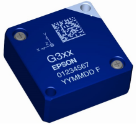
EPSON M-G3XX IMU/USB Interface Board

Evaluation board/kit and Development tool important notice
- This evaluation board/kit or development tool is designed for use for engineering evaluation, demonstration, or development purposes only. Do not use it for other purpose. It is not intended to meet the requirement of design for finished product.
- This evaluation board/kit or development tool is intended for use by an electronics engineer, and it is not the product for consumer. The user should use this goods properly and safely. Seiko Epson dose not assume any responsibility and liability of any kind of damage and/or fire coursed by usage of it. User should cease to use it when any abnormal issue occurs even during proper and safe use.
- The part used for this evaluation board/kit or development tool is changed without any notice.
Notice of the Document
NOTICEPLEASE READ CAREFULLY BELOW BEFORE THE USE OF THIS DOCUMENT ©Seiko Epson Corporation 2022
- The content of this document is subject to change without notice. Before purchasing or using Epson products, please contact with sales representative of Seiko Epson Corporation (“Epson”) for the latest information and be always sure to check the latest information published on Epson’s official web sites and resources.
- This document may not be copied, reproduced, or used for any other purposes, in whole or in part, without Epson’s prior consent.
- Information provided in this document including, but not limited to application circuits, programs and usage, is for reference purpose only. Epson makes no guarantees against any infringements or damages to any third parties’ intellectual property rights or any other rights resulting from the information. This document does not grant you any licenses, any intellectual property rights or any other rights with respect to Epson products owned by Epson or any third parties.
- Using Epson products, you shall be responsible for safe design in your products; that is, your hardware, software, and/or systems shall be designed enough to prevent any critical harm or damages to life, health or property, even if any malfunction or failure might be caused by Epson products. In designing your products with Epson products, please be sure to check and comply with the latest information regarding Epson products (including, but not limited to this document, specifications, data sheets, manuals, and Epson’s web site). Using technical contents such as product data, graphic and chart, and technical information, including programs, algorithms and application circuit examples under this document, you shall evaluate your products thoroughly both in stand-alone basis and within your overall systems. You shall be solely responsible for deciding whether to adopt/use Epson products with your products.
- Epson has prepared this document carefully to be accurate and dependable, but Epson does not guarantee that the information is always accurate and complete. Epson assumes no responsibility for any damages you incurred due to any misinformation in this document.
- No dismantling, analysis, reverse engineering, modification, alteration, adaptation, reproduction, etc., of Epson products is allowed.
- Epson products have been designed, developed and manufactured to be used in general electronic applications and specifically designated applications (“Anticipated Purpose”). Epson products are NOT intended for any use beyond the Anticipated Purpose that requires particular quality or extremely high reliability in order to refrain from causing any malfunction or failure leading to critical harm to life and health, serious property damage, or severe impact on society, including, but not limited to listed below (“Specific Purpose”).
Therefore, you are strongly advised to use Epson products only for the Anticipated Purpose. Should you desire to purchase and use Epson products for Specific Purpose, Epson makes no warranty and disclaims with respect to Epson products, whether express or implied, including without limitation any implied warranty of merchantability or fitness for any Specific Purpose. Please be sure to contact our sales representative in advance, if you desire Epson products for Specific Purpose:
Space equipment (artificial satellites, rockets, etc.)/Transportation vehicles and their control equipment (automobiles, aircraft, trains, ships, etc.)/Medical equipment/Relay equipment to be placed on sea floor/ Power station control equipment/Disaster or crime prevention equipment/Traffic control equipment/Financial equipment Other applications requiring similar levels of reliability as the above - Epson products listed in this document and our associated technologies shall not be used in any equipment or systems that laws and regulations in Japan or any other countries prohibits to manufacture, use or sell. Furthermore, Epson products and our associated technologies shall not be used for the purposes of military weapons development (e.g. mass destruction weapons), military use, or any other military applications. If exporting Epson products or our associated technologies, please be sure to comply with the Foreign Exchange and Foreign Trade Control Act in Japan, Export Administration Regulations in the U.S.A (EAR) and other export-related laws and regulations in Japan and any other countries and to follow their required procedures.
- Epson assumes no responsibility for any damages (whether direct or indirect) caused by or in relation with your non-compliance with the terms and conditions in this document or for any damages (whether direct or indirect) incurred by any third party that you give, transfer or assign Epson products.
- For more details or other concerns about this document, please contact our sales representative.
- Company names and product names listed in this document are trademarks or registered trademarks of their respective companies.
Overview
The IMU logger software (“Software”) is an easy-to-use software tool running on the Windows PC designed to collect data measured on the Inertial Measurement Unit (IMU) together with the USB Interface Board from Seiko Epson. The Software is offered as a loan to the customers who want to use or evaluate the IMU from Seiko EPSON. The Software supports maximum of 6 IMUs of the same model type for the measurement. Please do not launch multiple instances of the Software on the same PC. For information about how to install the Software, see Chapter 2. For information about how to use the Software, see Chapter 3.
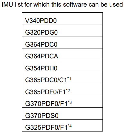
*1 G365PDC0/C1 is written as G365PDC in this document
*2 G365PDF0/F1 is written as G365PDF in this document
*3 G370PDF0/F1 is written as G370PDF in this document
*4 G325PDC0/C1 is written as G325PDC in this document

Preparation
Requirement
System Requirement
This sub-section describes the system requirement of the Software.
An IBM PC/AT compatible computer. The Software supports Windows 10 (64bit Edition). Other system environments are not tested by Seiko Epson. The required specifications for the IBM PC/AT compatible computer are as follows.
| Supported OS | Windows 10 (64bit) | |
| CPU | Recommended | 2.0GHz Over |
| RAM | Recommended | 2.0GB Over |
Other Required Software
- The Software requires the Microsoft .Net Framework 4.8 runtime. Download and install the Microsoft .Net Framework 4.8 runtime. Follow the Microsoft End-User License Agreement when the .Net Framework 4.8 runtime is installed and used.
- When the USB Interface board is connected to the PC, the USB driver software from FTDI is required. For information about the installation, see 2.2 Preparing to use the Software (2). Follow the terms of use provided by FTDI, when using the USB driver from FTDI.
Preparing to Use the Software
- Fix the IMU on and connect the IMU to the USB Interface Board and then connect a USB cable between the USB Interface Board and the PC.
- If the driver software (USB Serial Converter, USB Serial Port (COMx) is requested when the USB Interface board is connected, install the driver using either of the following two methods.
• Update the driver via Windows Device Manager. (Automatic Update over the Internet is recommended.)
• Access the FTDI website (http://www.ftdichip.com/Drivers/VCP.htm) and download the appropriate driver for the OS you are using. - If the display update of the Software is sluggish, go to Device Manager > USB Serial Port (COMx) > Port Settings > Advanced, and change the setting of the Latency Time (msec) in BM Options from “16” (default) to “1”. This may improve the situation.
Installing / Uninstalling the Software
Decompress the Software package under any folder and just double-click the executable file (Imulogger.exe) to start the Software. To uninstall the Software, delete the whole decompressed folder. (Registry settings are not used.)
Using the Software
This chapter describes basics of using the Software.
Starting the Software
Start the executable file of the Software (ImuLogger.exe). * When this software is started for the first time or the IMU model is changed, restart the software after setting “3.2.1 Serial port setting”.
Example of Main Screen when the attitude angle output is not supported with IMU model.
Example of Main Screen when the attitude angle output is supported with IMU model.


Setting
Start the executable file of the Software (ImuLogger.exe). Click the “Setup” tab in the upper part of the window and click the “Config” button to open the setup window. The setup window has three tabs: one for Serial Port settings, one for IMU settings, and one for Log settings. Click the “OK” to activate the settings and close the window.
Serial Port Settings
- Configure the “Connect” to control the connection to each IMU. When the IMU is “checked”, the connection is enabled.
- Configure the “Port”. Check the available port number for USB Serial Port (COMx) in the Device Manager. Baud rate setting is fixed at 460800 baud.
- The model number of the connected IMU is displayed in “IMU model”.
- After changing the Serial Port settings, restart the Software. After restarting, the settings will become effective.

IMU Settings
- In “Data Output Rate (Sps)”, specify the data output rate for the IMU. Select from the following options. (Sps: Samples / sec) – V340PDD 15.625, 31.25, 62.5, 125, 250, 500, 1000 (Sps) – Other Models 15.625, 20, 25, 31.25, 40, 62.5, 80, 100, 125, 200, 250, 400, 500, 1000, 2000 (Sps)
- In “Filter TAP Number”, configure the built-in filter in the IMU. Select from the following options.
– No Filter/TAP1
– Moving Average Filter: 2, 4, 8, 16, 32, 64, 128
– Kaiser Filter (parameter=8)
Tap32, 64, 128
Fc50, 100, 200, 400Hz
* Although it is possible to specify “No Filter/TAP1”, this setting is not recommended.
* Please refer to the appropriate IMU data sheet for recomended Filter TAP Number of each Data Output Rate(Sps)
* Kaiser filter is available only for G320PDG0, G364PDC0, G364PDCA, G354PDH0, G365PDC, G365PDF, G370PDF, G370PDS0, G325PDF.
* In G370 PDF1, G370PDS0, the Fc of the Kaiser filter changes depending on the Data Output Rate(Sps). The following table is displayed in “IMU Setting”. - “Basic Orientation” is available only for G365PDC, G365PDF, G325PDF. When this is the case, please specify the orientation of the IMU for X, Y and Z axis.
- In “Data Format”, specify the bit width of IMU output data. – 16bit Data – 32bit Data
* 32bit Data setting is only for G320PDG0, G364PDC0, G364PDCA, G354PDH0, G365PDC, G365PDF, G370PDF, G370PDS0,G325PDF.
* In case of 32bit Data setting, Maximum Data Output Rate (Sps) is 1,000 (Sps). - In “Count Function”, select SamplingCount or ResetCount.
- The “Attitude Output” conditions are configured in “angle”. – If “angle” is checked, it becomes enabled and active – Select Output mode “Absolute Inclinometer Mode” or “Euler Angle Mode” – Select “Data Format” to 16bit or 32bit for output
* Attitude Output is available only for G365PDC, G365PDF, G325PDF - If “Quaternion” is checked, it becomes enabled and active * Quaternion Output is available only for G365PDC1, G365PDF1, G325PDF1
- In “Attitude Motion Profile”, attitude motion profile mode can be set from “mode A”, “mode B”, and “mode C”. * Attitude Motion Profile is available only for G365PDC1, G365PDF1, G325PDF1

- Screen Image for V340PDD, G320PDG0, G364PDC0, G364PDCA, G354PDH0, .
- Screen Image for G365PDC, G365PDF, G325PDF


Log Settings
- In “Folder”, specify the full path of the log folder. Click the “…” button to the right and select
the log folder in the file selection dialog box.
* Default Log folder in the software is “C:\imu_data\”
* Please select the user accessible folder for the log folder. - In “Delimiter”, specify the delimiter character.
• Comma: Comma delimiter
• Tab: Tab delimiter - In “Unit”, specify the data format used when the measurement data are saved.
• Digit: Raw data
• Scale: Scale-adjusted data (raw data multiplied by the scale factor)
The unit of output value can be selected from the following.
Gyro:the unit of output value “dps” or “rad/s”
Accl:the unit of output value “mG” or “m/s2
”Attitude:the unit of output value “deg” or “rad” * only for G365PDC, G365PDF and G325PDF. - In “Comment”, specify the comment recorded in the beginning of the log file.
- In “CheckSum”, specify the logging of communication data error checking status.
- In “MaximumEntries”, specify the maximum sample entries per CSV “split” log file.
- In “MeasureControl”, specify the automatic sampling stop condition.
Set “Enable/disable automatic sampling stop” by “Termination condition” check.
The stop condition is set by time (Time) or sampling number (Count).
* The automatic sampling stop function is automatically disabled once it is executed

Starting / Stopping Sampling
- To save the measurement data to the log file, check “Save Log”.
- Click the “Start” button to start sampling.
- To stop sampling, click the “Stop” button.
* The automatic sampling stop function is cancelled when sampling is stopped manually.
(4) The measurement data are displayed on the window. When “Show Gyro Graph” or “Show Accl Graph” buttons are clicked, the specified plot graph is displayed. On the Graph window, the measurement data are displayed as numerical values and as a line graph. In “IMU Display Select”, select the IMU to display the measurement data for. To close the Graph window, click the close button (×) at the upper right corner of the window.
Note: Displaying the Graph window requires significant processing resources from the PC. To put more priority on log output, do not show the Graph window.


- Screen Image of Gyro Graph
- Screen Image of Accl Graph.
* When Overranging of a sensor axis is detected by the Software, the circle indicator located on the right side of the affected sensor axis turns RED.
* The Graph can be enlarged by using slide bar on the right side of Graph.


Self Test
To execute the self test, first click the “Setup” tab to allow access to the Self Test button.
The self test is executed on all the IMUs checked “Connect” in the Serial Port settings.
- Click the “Self-Test” to execute the self-test. The result will be displayed as either “OK” or “NG”.

Exiting the Software
Click the “Exit” button to exit the Software.
Display and Output Data of Attitude Angle
For G365PDC, G365PDF, G325PDF, when “angle” is checked, the attitude angle acquired from IMU is displayed. When “Save Log”is checked, the measurement is preserved in the log file.

When “Show Attitude Graph” button is clicked, a plot graph of the attitude angle is displayed.
On the Graph screen, measurements are expressed by numerical values and line graphs.
In “IMU Display Select”, select the IMU to display measurement values for. Push the close button (×) at the top right of the window to close the graph screen.
Note: Displaying the Graph window requires significant processing resources from the PC. To put more priority on log output, do not show the Graph window.

Automatic Sampling Stop

In the “MeasureContol” item on the Log Setting screen, sampling can be stopped automatically by “Termination condition” check.
The stop condition is set by the following items.
・” Time ” : Time specified in seconds
・” Count “:Count specified by sampling number
The automatic sampling stop function is effective only for the first sampling execution after enabling.
In the second and subsequent sampling, the automatic stop function is disabled and not performed.
When automatic stop is enabled, “Elapsed Time” indication of Logging Status becomes
“Remaining Time” to show the remaining time until automatic stop will occur.
*The automatic stop timing of sampling will vary from the set value depending on the processing capacity of the PC.

Log File
This chapter describes the LOG files created by the Software.
A LOG file is created for each IMU. For each IMU checked in the “Connect” in the Serial Port settings, the Software outputs a LOG file. The IMU number is added to the end of the filename of each LOG file
Raw Data LOG
This section describes items recorded when the raw data format is selected as the data format used for the LOG file.
- On the first line, the sampling start date and time (year, month, day, and time (unit: 1/100 second)) is printed (Based on the PC OS clock) and Logger version.
- On the second line, the IMU Product model number, Firmware version, Serial number.
- On the third line, the IMU Port number, sampling interval, Filter Type, number of TAPs are printed.
- On the fourth line, the scale factor of angular velocity and acceleration are printed.
(Note: The scale factor unit is different from the G370, G365, and G325 data sheets.
This software is designed to multiply the digit value by the scale factor value and convert it to a scale value.) - On the fifth line, the comment is printed.
- On the sixth line, the measurement data column heading are printed.
- On the seventh line and after, the measurement data are printed. The following items are recorded as the measurement data.
- Sample No: Sample number
- time: Elapsed time
(Note: The elapsed time represents the time generated in the built-in timer inside the IMU.) - Gx: Angular velocity (X-axis), Gy: Angular velocity (Y-axis), Gz: Angular velocity (Z-axis)
- Ax: Acceleration (X-axis), Ay: Acceleration (Y-axis), Az: Acceleration (Z axis)
- Ts: Temperature
(Note: This is a reference value used for internal temperature compensation. We provide no guarantee that the value gives an accurate representation of the internal temperature.) - GPIO: GPIO information *only for V340PDD0.
- Count: SamplingCount or ResetCount
- CheckSum:Checksum value , CheckResult:OK or NG
Output data image for V340PDD0

Scale-Adjusted Data LOG
This section describes items recorded when the scale-adjusted data format is selected as the data format used for the LOG file.
- On the first line, the sampling start date and time (year, month, day, and time (unit: 1/100 second)) is printed (Based on the PC OS clock) and Logger version.
- On the second line, the IMU Product model number, Firmware version, Serial number.
- On the third line, the IMU Port number, sampling interval, Filter Type, number of TAPs are printed.
- On the fifth line, the comment is printed.
- On the sixth line, the measurement data column heading are printed.
- On the seventh line and after, the measurement data are printed. The following items are recorded as the measurement data.
- Sample No: Sample number
- time: Elapsed time (Note: The elapsed time represents the time created by the built-in timer inside the IMU.)
- Gx: Angular velocity (X-axis), Gy: Angular velocity (Y-axis), Gz: Angular velocity (Z-axis)
- Ax: Acceleration (X-axis), Ay: Acceleration (Y-axis), Az: Acceleration (Z axis)
- ATotal: Summation of all the accelerations = (Ax^2 +Ay^2 + Az^2)^0.5
- Ts[degC]: Temperature in Celsius, Ts[degF]: Temperature in Fahrenheit
(Note: This is a reference value used for internal temperature compensation. We provide no guarantee that the value gives an accurate representation of the internal temperature.) - GPIO: GPIO information *Only for V340PDD0.
- Count: SamplingCount or ResetCount
- CheckSum:CheckSum value , CheckResult:OK or NG
Output data image for V340PDD0

Output data image for V364PDC0

Attitude Angle Sensor Data
This section describes the additional items recorded when outputting attitude angle information for G365PDC, G365PDF, G325PDF as the data format used for the LOG file.
- On the first line, the Basic Orientation information, the Angle Mode information and Attitude Motion Profile are added.
- On the fouth line, the Scale Factor of attitude angle output is added.
* when the raw data format is selected. - On the seventh line and after, the below measurement data are added as additional columns.
– Ang1: Angle, Ang2: Angle, Ang3: Angle
– QTN-0, QTN-1, QTN-2, QTN-3:Quaternion
* The attitude angle and the measurement axes are determined by Basic Orientation information.
Output data image for G365PDF0 when the raw data format is selected.

Split Log File

The sampling number to sub-divide or “split” the log file can be set by “MaximumEntries” of Log setting.
Number of samples that can be set.
- 「0」 : Do not sub-divide the log file
- 「100」~「999999」: Sampling number to sub-divide the log file
* When the setting value is “100” or less, it is automatically set to “100”.
For the split log file name, an incrementing count starting from 1 is appended after the IMU number.
Note
Depending on how other applications on the PC behave, some of the sampling data may not be acquired properly. If this situation happens, “NG” will be printed to fill in the missing measurement data and indicate a data error.

On Main Screen, “Data Error” message will show up in “Logging Status” as shown below.
When “Data Error” is detected, the Log file is saved with the “E” just before extension in log file name.
When logging with Checksum “ON” (enabled) in the Log setting, and the checksum result is NG, “Data Error” message will show up in “Logging Status” as shown adove and the Log file is saved with the “E” just before extension in log file name.
Revision History
| Rev. No. | Date | Page | Contents |
| Rev 20140328 | 2014/3/28 | All | Newly established |
| Rev 20160301 | 2016/3/1 | Page1,2,3,4, 5,6,7,8,11 | G364PDC0, G364PDCA, G354PDH0,Additions |
| Rev 20160606 | 2016/6/6 | Page 13,14,15 | Information of log file |
| Rev 20160712 | 2016/7/12 | Page 13,14,15 | ResetCount , Production information( the IMU Product model number, Firmware version,Serial number ) Additions |
| Rev 20170307 | 2017/3/7 | Page 5 | ‘NoFilter/TAP1’ |
| Rev 20180803 | 2018/8/3 | All | Version upgrade(Ver3.0) of IMU-Logger |
| Rev 20180821 | 2018/8/21 | Page7,13,14 | Add Explanation of “CheckSum” |
| Rev 20181129 | 2018/11/29 | All | Version upgrade(Ver3.2) of IMU-Logger |
| Rev 20190206 | 2019/2/6 | Page14,15 | Information of log file |
| Rev 20190628 | 2019/6/28 | Page6 | Change Images |
| Rev 20191004 | 2019/10//4 | Page1,4,5,6, 7,11,15 | G352PDF0 addition, Display image change, Attitude angle Log output hedear change |
| Rev 20200821 | 2020/8/21 | Page1,5,6,7, 15 | Quaternion output and Attitude motion profile are additions , Cahnge Images, Change header of attitude angle log G370PDC0 deletion |
| Rev 20201020 | 2020/10/20 | Page5 | Add Explanation of Data Output Rate and filter display in G370PDF1 |
| Rev 20220307 | 2022/03/07 | Page1,2,5,6, 7 | Supported OS, Windows 7 removed Updated to .Net Framework 4.8 G370PDS0 addition, |
AMERICA
EPSON AMERICA, INC.
214 Devcon Drive,
San Jose, CA 95112, USA
Phone: +1-800-228-3964 FAX: +1-408-922-0238
EUROPE
EPSON EUROPE ELECTRONICS GmbH
Riesstrasse 15, 80992 Munich,
GERMANY
Phone: +49-89-14005-0 FAX: +49-89-14005-110
ASIA
EPSON (CHINA) CO., LTD.
4F,Tower 1 of China Central Place,81 Jianguo Street, Chaoyang District,
Beijing 100025 CHINA
Phone: +86-400-810-9972 X ext.2
Mail
EPSON SINGAPORE PTE. LTD.
438B Alexandra Road, Block B Alexandra TechnoPark, #04-
01/04, Singapore 119968
Phone: +65-6586-5500 FAX: +65-6271-3182
EPSON TAIWAN TECHNOLOGY & TRADING LTD.
14F, No. 7, Song Ren Road,
Taipei 110, TAIWAN
Phone: +886-2-8786-6688 Fax: +886-2-8786-6660
EPSON KOREA Co., Ltd.
10F Posco Tower Yeoksam, Teheranro 134 Gangnam-gu,
Seoul, 06235 KOREA
Phone: +82-2-558-4270 Fax: +82-2-3420-6699
JAPAN
SEIKO EPSON CORPORATION. MD SALES & MARKETING DEPT.
29th Floor, JR Shinjuku Miraina Tower, 4-1-6 Shinjuku, Shinjuku-ku,
Tokyo, 160-8801, Japan
Phone: +81-3-6682-4322 FAX: +81-3-6682-5016