Makita HS6601 Circular Saw Instruction Manual


Circular Saw
Instruction Manual
HS6601


SPECIFICATIONS
| Model: | HS6601 | |
| Blade diameter | 165 mm | |
| Max. Cutting depth | at 0° | 54.5 mm |
| at 45° | 37.5 mm | |
| No-load speed | 5,200 min-1 | |
| Overall length | 296 mm | |
| Net weight | 3.7 kg | |
| Safety class | ||

- Due to our continuing program of research and development, the specifications herein are subject to change without notice.
- Specifications may differ from country to country.
- Weight according to EPTA-Procedure 01/2003
Intended use
The tool is intended for performing lengthways and crossways straight cuts and miter cuts with angles in wood while in firm contact with the workpiece. With appropriate Makita genuine saw blades, other materials can also be sawed.
Power supply
The tool should be connected only to a power supply of the same voltage as indicated on the nameplate, and can only be operated on a single-phase AC supply. They are double-insulated and can, therefore, also be used from sockets without earth wire.
Noise
The typical A-weighted noise level is determined according to EN60745:
Sound pressure level (LpA): 87 dB(A)
Sound power level (LWA): 98 dB (A)
Uncertainty (K) : 3 dB(A)
Vibration
The vibration total value (tri-axial vector sum) determined according to EN60745:
Work mode: cutting wood
Vibration emission (ah,W) : 2.5 m/s 2 or less
Uncertainty (K) : 1.5 m/s 2
NOTE: The declared vibration emission value has been measured in accordance with the standard test method and may be used for comparing one tool with another.
NOTE: The declared vibration emission value may also be used in a preliminary assessment of exposure.
EC Declaration of Conformity
For European countries only
Makita declares that the following Machine(s):
Designation of Machine: Circular Saw
Model No./ Type: HS6601
Conforms to the following European Directives: 2006/42/EC
They are manufactured in accordance with the following standard or standardized documents: EN60745
The technical file in accordance with 2006/42/EC is available from Makita, Jan-Baptist Vinkstraat 2, 3070, Belgium 24.4.2015
Yasushi Fukaya
Director
Makita, Jan-Baptist Vinkstraat 2, 3070, Belgium


General power tool safety warnings
Save all warnings and instructions for future reference.
The term “power tool” in the warnings refers to your mains-operated (corded) power tool or battery-operated (cordless) power tool.
Circular saw safety warnings
Cutting procedures
- Do not reach underneath the workpiece. The guard cannot protect you from the blade below the workpiece.
- Adjust the cutting depth to the thickness of the workpiece. Less than a full tooth of the blade teeth should be visible below the workpiece.
- Never hold piece being cut in your hands or across your leg. Secure the workpiece to a stable platform. It is important to support the work properly to minimize body exposure, blade binding, or loss of control.
► Fig.1 - Hold the power tool by insulated gripping surfaces only, when performing an operation where the cutting tool may contact hidden wiring or its own cord. Contact with a “live” wire will also make exposed metal parts of the power tool “live” and could give the operator an electric shock.
- When ripping, always use a rip fence or straight edge guide. This improves the accuracy of the cut and reduces the chance of blade binding.
- Always use blades with the correct size and shape (diamond versus round) of arbor holes. Blades that do not match the mounting hardware of the saw will run eccentrically, causing a loss of control.
- Never use damaged or incorrect blade washers or bolts. The blade washers and bolt were specially designed for your saw, for optimum performance and safety of operation.
Kickback causes and related warnings
— kickback is a sudden reaction to a pinched, bound or misaligned saw blade, causing an uncontrolled saw to lift up and out of the workpiece toward the operator;
— when the blade is pinched or bound tightly by the kerf closing down, the blade stalls, and the motor reaction drives the unit rapidly back toward the operator;
— if the blade becomes twisted or misaligned in the cut, the teeth at the back edge of the blade can dig into the top surface of the wood causing the blade to climb out of the kerf and jump back toward the operator.
Kickback is the result of saw misuse and/or incorrect operating procedures or conditions and can be avoided by taking proper precautions as given below.
- Maintain a firm grip with both hands on the saw and position your arms to resist kickback forces. Position your body to either side of the blade, but not in line with the blade. Kickback could cause the saw to jump backward, but kickback forces can be controlled by the operator, if proper precautions are taken.
- When blade is binding, or when interrupting a cut for any reason, release the trigger and hold the saw motionless in the material until the blade comes to a complete stop. Never attempt to remove the saw from the work or pull the saw backward while the blade is in motion or kickback may occur. Investigate and take corrective actions to eliminate the cause of blade binding.
- When restarting a saw in the workpiece, center the saw blade in the kerf and check those saw teeth are not engaged in the material. If the saw blade is binding, it may walk up or kick back from the workpiece as the saw is restarted.
- Support large panels to minimize the risk of blade pinching and kickback. Large panels tend to sag under their own weight. Supports must be placed under the panel on both sides, near the line of cut and near the edge of the panel.
► Fig.2 ► Fig.3 - Do not use dull or damaged blades. Unsharpened or improperly set blades produce narrow kerf causing excessive friction, blade binding, and kickback.
- Blade depth and bevel adjusting locking levers must be tight and secure before making cuts. If blade adjustment shifts while cutting, it may cause binding and kickback.
- Use extra caution when sawing into existing walls or other blind areas. The protruding blade may cut objects that can cause kickback.
- ALWAYS hold the tool firmly with both hands. NEVER place your hand, leg or any part of your body under the tool base or behind the saw, especially when making cross-cuts. If kickback occurs, the saw could easily jump backward over your hand, leading to serious personal injury.
► Fig.4 - Never force the saw. Push the saw forward at a speed so that the blade cuts without slowing. Forcing the saw can cause uneven cuts, loss of accuracy, and possible kickback.
Lower guard function
- Check lower guard for proper closing before each use. Do not operate the saw if the lower guard does not move freely and close instantly. Never clamp or tie the lower guard into the open position. If the saw is accidentally dropped, the lower guard may be bent. Raise the lower guard with the retracting handle and make sure it moves freely and does not touch the blade or any other part, in all angles and depths of cut.
- Check the operation of the lower guard spring the guard and the spring are not operating properly, they must be serviced before use. The lower guard may operate sluggishly due to damaged parts, gummy deposits, or a build-up of debris.
- The lower guard may be retracted manually only for special cuts such as “plunge cuts” and “compound cuts”. Raise the lower guard by retracting the handle and as soon as the blade enters the material, the lower guard must be released. For all other sawing, the lower guard should operate automatically.
- Always observe that the lower guard is covering the blade before placing the saw down on the bench or floor. An unprotected, coasting blade will cause the saw to walk backward, cutting whatever is in its path. Be aware of the time it takes for the blade to stop after the switch is released.
- To check the lower guard, open the lower guard by hand, then release and watch guard closure. Also, check to see that retracting handle does not touch the tool housing. Leaving the blade exposed is VERY DANGEROUS and can lead to serious personal injury.
Additional safety warnings
- Use extra caution when cutting damp wood, pressure-treated lumber, or wood containing knots. Maintain smooth advancement of the tool without a decrease in blade speed to avoid overheating the blade tips.
- Do not attempt to remove cut material when the blade is moving. Wait until the blade stops before grasping the cut material. Blades coast after turn-off.
- Avoid cutting nails. Inspect for and remove all nails from lumber before cutting.
- Place the wider portion of the saw base on that part of the workpiece which is solidly supported, not on the section that will fall off when the cut is made. If the workpiece is short or small, clamp it down. DO NOT TRY TO HOLD SHORT PIECES BY HAND!
► Fig.5 - Before setting the tool down after completing a cut, be sure that the guard has closed and the blade has come to a complete stop.
- Never attempt to saw with the circular saw held upside down in a vise. This is extremely dangerous and can lead to serious accidents.
► Fig.6 - Some material contains chemicals that may be toxic. Take caution to prevent dust inhalation and skin contact. Follow material supplier safety data.
- Do not stop the blades by lateral pressure on the saw blade.
- Do not use any abrasive wheels.
- Only use the saw blade with the diameter that is marked on the tool or specified in the manual. Use of an incorrectly sized blade may affect the proper guarding of the blade or guard operation which could result in serious personal injury.
- Keep the blade sharp and clean. Gum and wood pitch hardened on blades slows the saw and increases the potential for kickback. Keep the blade clean by first removing it from tool, then cleaning it with gum and pitch remover, hot water or kerosene. Never use gasoline.
- Wear a dust mask and hearing protection when use the tool.
SAVE THESE INSTRUCTIONS.
FUNCTIONAL DESCRIPTION
Adjusting the depth of cut
► Fig.7: 1. Lever
Loosen the lever on the depth guide and move the base up or down. At the desired depth of cut, secure the base by tightening the lever. For cleaner, safer cuts set cut depth so that no more than one blade tooth projects below the workpiece. Using proper cut depth helps to reduce the potential for dangerous KICKBACKS which can cause personal injury.
Bevel cutting
► Fig.8: 1. Clamping screw 2. Bevel scale plate
► Fig.9: 1. Clamping screw
Loosen the clamping screws. Set for the desired angle (0° – 45°)by tilting accordingly, then tighten the clamping screws securely.
Sighting
► Fig.10: 1. Cutting line (0° position) 2. Cutting line (45° position)
For straight cuts, align the 0° position on the front of the base with your cutting line. For 45° bevel cuts, align the 45° position with it.
Switch action
► Fig.11: 1. Switch trigger 2. Lock-off button
To prevent the switch trigger from being accidentally pulled, a lock-off button is provided. To start the tool, depress the lock-off button and pull the switch trigger. Release the switch trigger to stop.
NOTICE: Do not pull the switch trigger hard without pressing in the lock-off button. This can cause switch breakage.
ASSEMBLY
Removing or installing circular saw blade
► Fig.12
- Hex wrench
- Shaft lock
- Loosen
- Tighten
For tool without the ring ► Fig.13:
- Hex bolt
- Outer flange
- Circular saw blade
- Inner flange For tool with the ring
► Fig.14:
- Hex bolt
- Outer flange
- Circular saw blade
- Ring
- Inner flange
To install the circular saw blade, follow the removal procedure in reverse.
For tool with an inner flange other than 15.88 mm, hole-diameter saw blade
The inner flange has a certain diameter protrusion on one side of it and a different diameter protrusion on the other side. Choose the correct side on which protrusion fits into the saw blade hole perfectly. Mount the inner flange onto the mounting shaft so that the correct side of protrusion on the inner flange faces outward and then place the saw blade and outer flange.
► Fig.15:
- Mounting shaft
- Inner flange
- Circular saw blade
- Outer flange
- Hex bolt
For tool with the inner flange for a 15.88 mm hole-diameter saw blade (country-specific)
Mount the inner flange with its recessed side facing outward onto the mounting shaft and then place saw blade (with the ring attached if needed), outer flange and hex bolt.
For tool without the ring ► Fig.16:
- Mounting shaft
- Inner flange
- Circular saw blade
- Outer flange
- Hex bolt
For tool with the ring ► Fig.17:
- Mounting shaft
- Inner flange
- Circular saw blade
- Outer flange
- Hex bolt
- Ring
Blade guard cleaning
When changing the circular saw blade, make sure to also clean the upper and lower blade guards of accumulated sawdust as discussed in the Maintenance section. Such efforts do not replace the need to check lower guard operation before each use.
Hex wrench storage ► Fig.18: 1. Hex wrench
When not in use, store the hex wrench as shown in the figure to keep it from being lost.
Connecting a vacuum cleaner
Optional accessory
When you wish to perform clean cutting operation, connect a Makita vacuum cleaner to your tool. Connect a hose of the vacuum cleaner to the dust nozzle as shown in the figure.
► Fig.19: 1. Dust nozzle 2. Screw
► Fig.20: 1. Hose 2. Vacuum cleaner
OPERATION
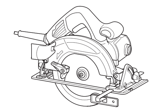
► Fig.21
Hold the tool firmly. The tool is provided with both a front grip and rear handle. Use both to best grasp the tool. If both hands are holding saw, they cannot be cut by the circular saw blade. Set the base on the workpiece to be cut without the circular saw blade making any contact. Then turn the tool on and wait until the circular saw blade attains full speed. Now simply move the tool forward over the workpiece surface, keeping it flat and advancing smoothly until the sawing is completed. To get clean cuts, keep your sawing line straight and your speed of advance uniform. If the cut fails to properly follow your intended cut line, do not attempt to turn or force the tool back to the cut line. Doing so may bind the circular saw blade and lead to dangerous kickback and possible serious injury. Release switch, wait for circular saw blade to stop and then withdraw tool. Realign tool on new cut line, and start cut again. Attempt to avoid positioning which exposes the operator to chips and wood dust being ejected from saw. Use eye protection to help avoid injury.
Rip fence (Guide rule)
Optional accessory
► Fig.22:
- Rip fence (Guide rule)
- Clamping screw
The handy rip fence allows you to do extra-accurate straight cuts. Simply slide the rip fence up snugly against the side of the workpiece and secure it in position with the clamping screw on the front of the base. It also makes repeated cuts of uniform width possible.
MAINTENANCE
NOTICE: Never use gasoline, benzene, thinner, alcohol or the like. Discoloration, deformation or cracks may result.
Adjusting the parallelism
► Fig.23: 1. Screw
This adjustment has been made at the factory. But if it is off, you can adjust it as the following procedure.
- Make sure all levers and screws are tightened. Slightly loosen the screw illustrated.
- While opening the lower guard, move the rear of the base so that the distance A and B becomes equal.
- Tighten the screws and make a test cut to check the parallelism.
Adjusting 0°-cut accuracy
► Fig.24: 1. Adjusting bolt
► Fig.25: 1. Triangular rule 2. Clamping screw
This adjustment has been made at the factory. But if it is off, you can adjust it as the following procedure.
- Slightly loosen the clamping screws on the front and rear of the tool.
- Make the base perpendicular to the blade using a triangular rule or square rule by turning the adjusting bolt.
- Tighten the clamping screws and make a test cut to check the verticalness.
Replacing carbon brushes ► Fig.26: 1. Limit mark
Check the carbon brushes regularly. Replace them when they wear down to the limit mark. Keep the carbon brushes clean and free to slip in the holders. Both carbon brushes should be replaced at the same time. Use only identical carbon brushes.
- Use a screwdriver to remove the brush holder caps.
- Take out the worn carbon brushes, insert the new ones and secure the brush holder caps.
► Fig.27: 1. Brush holder cap
To maintain product SAFETY and RELIABILITY, repairs, and any other maintenance or adjustment should be performed by Makita Authorized or Factory Service Centers, always using Makita replacement parts.
OPTIONAL ACCESSORIES
CAUTION: These accessories or attachments are recommended for use with your Makita tool specified in this manual. The use of any other accessories or attachments might present a risk of injury to persons. Only use accessory or attachment for its stated purpose.
If you need any assistance with more details regarding these accessories, ask your local Makita Service Center.
- Circular saw blade
- Rip fence (Guide rule)
- Hex wrench
- Dust nozzle
- Guide rail
- Bevel guide
- Clamp
- Sheet
- Rubber sheet
- Position sheet
- Guide rail adapter
- Rule bar
NOTE: Some items in the list may be included in the tool package as standard accessories. They may differ from country to country.

Makita Jan-Baptist Vinkstraat 2, 3070, Belgium
Makita Corporation Anjo, Aichi, Japan
www.makita.com