KENWOOD X502-1 XM502-1 Class D Mono Power Amplifier Instruction Manual


KENWOOD X502-1 XM502-1 Class D Mono Power Amplifier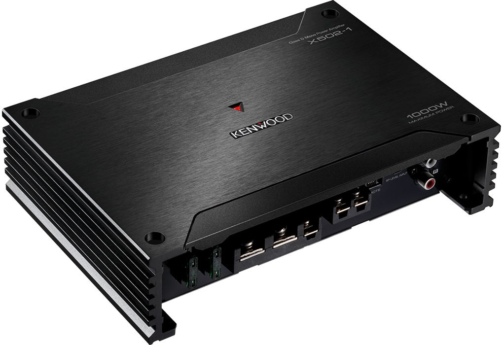


Dimensions

Safety precautions
WARNING
To prevent injury or fire, take the following precautions:
- Mounting and wiring this product requires skills and experience. For safety’s sake, leave the mounting and wiring work to professionals.
- When extending the ignition, battery, or ground wires, make sure to use automotive-grade wires or other wires with the range of 5 mm2 (AWG 10) or more to prevent wire deterioration and damage to the wire coating.
- To prevent a short circuit, never put or leave any metallic objects (such as coins or metal tools) inside the unit.
- If the unit starts to emit smoke or strange smells, turn off the power immediately and consult your KENWOOD dealer.
- Do not touch the unit during use because the surface of the unit becomes hot and may cause burns if touched.
CAUTION
To prevent damage to the machine, take the following precautions:
- Be sure the unit is connected to a 12 V DC power supply with a negative ground connection.
- Do not open the top or bottom covers of the unit.
- Do not install the unit in a spot exposed to direct sunlight or excessive heat or humidity. Also, avoid places with too much dust or the possibility of water splashing.
- When replacing a fuse, only use a new one with the prescribed rating. Using a fuse with the wrong rating may cause your unit to malfunction.
- To prevent a short circuit when replacing a fuse, first, disconnect the wiring harness.
NOTE - If you experience problems during installation, consult your KENWOOD dealer.
- If the unit does not seem to be working right, consult your KENWOOD dealer.
Cleaning the unit
If the front panel gets dirty, turn off the power and wipe the panel with a dry silicon cloth or soft cloth.
CAUTION
Do not wipe the panel with a hard cloth or a cloth dampened by volatile solvents such as paint thinner and alcohol. They can scratch the surface of the panel and/or cause the indicator letters to peel off.
To prevent battery rise
When the unit is used in the ACC ON position without turning the engine ON, it depletes the battery. Use it after starting the engine.
Protection function
The protection function is activated in the following situations:
This unit is equipped with a protection function for protecting this unit and your speakers from various accidents or problems that can occur.
When the protection function is triggered, the power indicator goes off and the amplifier stops operating.
- When a speaker wire may be short-circuited.
- When a speaker output contacts the ground.
- When the unit malfunctions and a DC signal is sent to the speaker output.
- When the internal temperature is high and the unit won’t operate.
Wiring
- Take the battery wire for this unit directly from the battery. If it’s connected to the vehicle’s wiring harness, it can cause blown fuses, etc.
- If a buzzing noise is heard from the speakers when the engine is running, connect a line noise filter (optional) to each of the battery wires.
- Do not allow the wire to directly contact the edge of the iron plate by using Grommets.
- Connect the ground wire to a metal part of the car chassis that acts as an electrical ground passing electricity to the battery‘s negative⊖terminal. Do not turn the power on if the ground wire is not connected.
- Be sure to install a protective fuse in the power cord near the battery. The protective fuse should be the same capacity as the unit’s fuse capacity or somewhat larger.
- For the power cord and ground, use a vehicle-type (fireproof ) power wring cord. (Use a power wiring cord with the range of 5 mm2 (AWG 10) or more.)
- When more than one power amplifier is going to be used, use a power supply wiring wire and protective fuse of greater current-handling capacity than the total maximum current drawn by each amplifier.
Speaker selection
- Using speakers with smaller input ratings than the amplifier’s output power would result in smoke generation or equipment failure.
- Use speakers that have an impedance of 2 Ω or greater. When more than one set of speakers is going to be used, calculate the combined impedance of the speakers and then connect suitable speakers to the amplifier. <Example>
Installation


NOTE
After wiring, fix the protective cover securely with screws and washers.
Installation procedure
Since there are large variety of settings and connections possible according to applications, read the instruction manual well to select the proper setting and connection.
- Remove the ignition key and disconnect the negative ⊖ terminal of the battery to prevent short circuits.
- Set the unit according to the intended usage.
- Remove the Dressing cover.
- Connect the input and output wires of the units.
- Connect the speaker wires.
- Connect the power wire, power control wire and grounding wire following this order.
- Install the installation fittings in the unit.
- Attach the unit.
- Attach the Dressing cover.
- Connect the negative ⊖ terminal of the battery.
CAUTION
- Do not install in the below locations;(Unstable location, In a location that interferes with driving, In a location that gets wet, In a dusty location, In a place that gets hot, In a place that gets direct sunlight, In a location that gets hit by hot air)
- Do not install the unit under the carpet. Otherwise, heat build-up occurs and the unit may be damaged.
- Install this unit in a location that allows heat to easily dissipate. Once installed, do not place any object on top of the unit.
The surface temperature of the amplifier will become hot during use. Install the amplifier in a place where people, resins, and other substances that are sensitive to heat will not come into contact with it. - When making a hole under a seat, inside the trunk, or somewhere else in the vehicle, check that there is nothing hazardous on the opposite side such as a gasoline tank, brake pipe, or wiring harness, and be careful not to cause scratches or other damage.
- Do not install near the dashboard, rear tray, or airbag safety parts.
- The installation to the vehicle should securely fasten the unit to a place in which it will not obstruct driving. If the unit comes off due to a shock and hits a person or safety part, it may cause injury or an accident.
- After installing the unit, check to make sure that electrical equipment such as the brake lamps, turn signal lamps and windshield wipers operate normally.
Connections
WARNING: Remove the ignition key and disconnect the negative⊖ terminal of the battery to prevent short circuits.
In a computer-equipped vehicle, when you remove the ⊖terminal of the battery, the memory may disappear, or a defect may occur in the electrical system of the vehicle. Consult your dealer for further details.
WARNING
Particular attention must be given to making good electrical contact at the amplifier-out-put and speaker terminals. Poor or loose connections can cause sparking or burn at the terminals because of the very high power that the amplifier can deliver.
CAUTION
- If the sound is not output normally, immediately turn the power off and check connections.
- Be sure to turn the power off before changing the setting of any switch.
- If the fuse blows, check wires for shorts, then replace the fuse with one of the same ratings.
- Check that no unconnected wires or connections are touching the car body. Do not remove caps from unconnected wires or connectors to prevent short circuits.
- Connect the speaker wires to appropriate speaker connectors separately. Sharing the negative wire of the speaker or grounding speaker wires to the metal body of the car can cause this unit to fail.
- After installation, check that the brake lamps, turn signal lamps and windshield wipers work properly.
Power wire and speaker wire connection


Speaker-level input connections
NOTE
Do not connect cables and leads to both RCA cable input jacks and the speaker level input terminals simultaneously, for this may cause malfunction or damage.

Controls

- Fuse (30 Ax 2)
NOTE: If you can’t find the specified capacity fuse at your store etc., consult your KENWOOD dealer. - Battery terminal (POWER IN BATT.)
- ground terminal (GND)
- A power control terminal (P.CON)
Controls the unit ON /OFF. - SPEAKER OUTPUT terminals
As this unit accepts speakers with a minimum impedance of 2 ohms, connect speakers with 2- ohm or higher impedance to these terminals. - REMOTE terminal
(for separately available part KC A-RC01A)
This terminal is an exclusive terminal for a controller to adjust the volume. - SP LEVEL INPUT terminal
The output from the FACTORY INSTALLED HEAD UNIT up to SOW can be input. The power is turned on and off as the unit detects the input signal (SIGNAL SENSING TURN-ON). Therefore it is not necessary to connect the power control wire. - LINE IN terminal
- INPUT SENSITIVITY control
Set this control according to the pre-output level of the HEAD UNIT connected with this unit.
NOTE: For the pre-output level, refer to the “Specifications” in the instruction manual of the HEAD UNIT. - INFRASONIC FILTER switch
Ultralow frequencies that cannot be reproduced even by a subwoofer speaker do not become sound but become unnecessary oscillations, which affect the sound by causing distortion, etc. When this switch is set to “ON’; the inaudible, ultralow frequencies are cut off. (Frequencies below 25 Hz are cut.) This improves the reproduction performance of the speakers by eliminating unnecessary oscillations which will not become sound. - BASS BOOS T LEVEL control
Sets the low-frequency level to be compensated. - LPF FREQUENCY control
This control adjusts the frequency band output from this unit. - Power indicator
When the power is turned on, the Power indicator lights,
Troubleshooting Guide
What might appear to be a malfunction in your unit may just be the result of slight misoperation or miswiring. Before calling the service, first check the following table for possible problems.
| PROBLEM | POSSIBLE CAUSE | SOLUTION |
| No sound.
(No sound from one side.) (Blown fuse.) |
• Input (or output) cables are disconnected. • Protection circuit may be activated. • Volume is too high. • The speaker cord is shorted. |
• Connect the input (or output) cables. • Check connections by referring to “Protection function”. • Replace the fuse and use lower volume. • After check the speaker cord and fixing the cause of the short, replace the fuse. |
| The output level is too small (or too large). | • The input sensitivity adjusting control is not set to the correct position. | • Adjust the control correctly referring to “Controls”. |
| The sound quality is bad.
(The sound is distorted.) |
• The speakers wire are connected with wrong ⊕/⊖ polarity. • A speaker wire is pinched by a screw in the car body. • The switches may be set improperly. |
• Connect them properly checking the ⊕/⊖ of the terminals and wires well. • Connect the speaker wire again so that it is not pinched by anything. • Set switches properly by referring to “Controls”. |
Specifications
- Specifications are subject to change without notice.
- Audio section
- Rated power output (+B=14.4 V)
(4 Ω) (20 Hz–200 Hz, ≤ 1.0% THD) ………………………….300 W×1
(2 Ω) (100 Hz, ≤ 1.0% THD)………………………………………..500 W×1 - Speaker impedance………………………..4 Ω (2 Ω to 8 Ω allowable)
- Frequency response (+0, −3 dB)………………………..20 Hz–200 Hz
- Input sensitivity (RCA)……………………………………………………0.2 V–5.0 V
- Signal to noise ratio……………………………………………………………….100 dB
- Input impedance…………………………………………………………………….. 10 kΩ
- Low pass filter frequency (−24 dB /oct.) …………………………………………………………..50 Hz–200 Hz (variable)
- Infrasonic filter frequency (−24 dB /oct.)…………………………25 Hz
- Bass boost control (40 Hz) ……………………….0 –+18 dB (variable
General
- Operating voltage…………………………………………12 V DC car battery
- Current consumption………………………………………………………………. 25 A
- Dimensions (W×H×D)……………………………….213×53×149 mm 8-3/8×2-1/16×5-7/8 inch
- Weight………………………………………………………………………….1.5 kg (3.3 lbs) 300 Watts RMS×1 at 4 Ohms and ≤ 1% THD+N 85 dBA (Reference: 1 Watt into 4 Ohms)
For Europe
X502-1 only
- Declaration of Conformity with regard to the EMC Directive 2014/30/EU
- Declaration of Conformity with regard to the RoHS Directive 2011/65/EU
- Manufacturer: JVCKENWOOD Corporation 3-12, Moriya-cho, Kanagawa-ku, Yokohama-shi, Kanagawa, 221-0022, JAPAN
Information on Disposal of Old Electrical and Electronic Equipment (applicable for countries that have adopted separate waste collection systems) Products with the symbol (crossed-out wheeled bin) cannot be disposed of as household waste. Old electrical and electronic equipment should be recycled at a facility capable of handling these items and their waste byproducts. Contact your local authority for details on locating a recycling facility nearest to you. Proper recycling and waste disposal will help conserve resources whilst preventing detrimental effects on our health and the environment.
X502-1 only / X502-1 uniquement / X502-1 solamente
- Declaration of Conformity with regard to the Electromagnetic Compatibility Regulations 2016 (S.I. 2016/1091)
- Declaration of Conformity with regard to the Restriction of the Use of Certain Hazardous Substances in Electrical and Electronic Equipment Regulations 2012 (S.I. 2012/3032)
For the U.S.A.
FCC CAUTION
Changes or modifications not expressly approved by the party responsible for compliance could void the user’s authority to operate the equipment.
NOTE: This equipment has been tested and found to comply with the limits for a Class B digital device, pursuant to part 15 of the FCC Rules. These limits are designed to provide reasonable protection against harmful interference in a residential installation. This equipment generates, uses, and can radiate radio frequency energy and, if not installed and used in accordance with the instructions, may cause harmful interference to radio communications. However, there is no guarantee that interference will not occur in a particular installation. If this equipment does cause harmful interference to radio or television reception, which can be determined by turning the equipment off and on, the user is encouraged to try to correct the interference by one or more of the following measures:
- Reorient or relocate the receiving antenna.
- Increase the separation between the equipment and receiver.
- Connect the equipment into an outlet on a circuit different from that to which the receiver is connected.
- Consult the dealer or an experienced radio/TV technician
Supplier’s Declaration of Conformity
- Trade Name: KENWOOD
- Products: CLASS D MONO POWER AMPLIFIER
- Model Name: X502-1 /XM502-1
- Responsible Party: JVCKENWOOD USA CORPORATION 2201 East Dominguez Street, Long Beach, CA 90810, U.S.A.
- PHONE: 310 639-9000
THIS DEVICE COMPLIES WITH PART 15 OF THE FCC RULES. OPERATION IS SUBJECT TO THE FOLLOWING
TWO CONDITIONS:
(1) THIS DEVICE MAY NOT CAUSE HARMFUL INTERFERENCE, AND
(2) THIS DEVICE MUST ACCEPT ANY INTERFERENCE RECEIVED, INCLUDING INTERFERENCE THAT MAY CAUSE UNDESIRED OPERATION.