Panasonic Wall Mount Bracket User Manual


Included Installation Instructions
Wall Mount Bracket
Model No.
WV-QWL500-W
WV-QWL500-G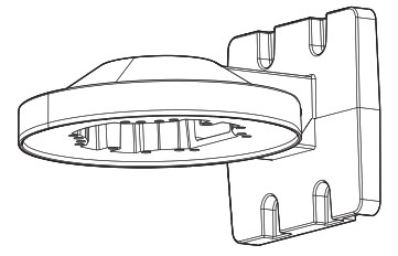

- Before attempting to connect or install this product, please read these instructions carefully and save this manual for future use.
- The external appearance and other parts shown in this manual may differ from the actual product within the scope that will not interfere with normal use due to improvement of the product.
Panasonic i-PRO Sensing Solutions Co., Ltd. assumes no responsibility for injuries or property damage resulting from failures arising out of improper installation or operation inconsistent with this documentation.
For U.S. and Canada:
Panasonic i-PRO Sensing Solutions
Corporation of America
800 Gessner Rd, Suite 700 Houston, TX 77024
https://www.security.us.panasonic.com/
Panasonic Canada Inc.
5770 Ambler Drive, Mississauga, Ontario, L4W 2T3 Canada
1-877-495-0580
https://www.panasonic.com/ca/
For Europe and other countries:
Panasonic Corporation
http://www.panasonic.com
Panasonic i-PRO Sensing Solutions Co., Ltd.
Fukuoka, Japan
Authorised Representative in EU:
Panasonic Testing Centre
Panasonic Marketing Europe GmbH
Winsbergring 15, 22525 Hamburg, Germany
© Panasonic i-PRO Sensing Solutions Co., Ltd. 2020
Fs0320-0 Printed in China

Preface
This product is used to attach dome-type cameras facing down on a wall. For the latest information about the supported cameras, refer to our support website (https://security.panasonic.com/training_support/support/info/<Control
No.: C0501, C0502, C0112>).
Specifications
| Ambient operating temperature: | –50 °C to +60 °C {–58 °F to +140 °F} |
| Dimensions: | 158 mm (W) × 112 mm (H) × 188 mm (D) {6-7/32 inches (W) × 4-13/32 inches (H) × 7-13/32 inches (D)} |
| Mass: | Approx. 520 g {1.15 lbs} |
| Finish: | Aluminum die-cast WV-QWL500-W: i-PRO white WV-QWL500-G: Light gray |
Precaution
- Refer installation work to the dealer.
Installation work requires technique and experience. Failure to observe this may cause fire, electric shock, injury, or damage to the product. Be sure to consult the dealer. - Install the product securely on a wall in accordance with the installation instructions.
Failure to observe this may cause injury or accidents. - Do not use this bracket except with suitable cameras.
Failure to observe this may cause a drop resulting in injury or accidents. - Do not install this product on a place that is greatly influenced by wind.
Installation on a place where the wind speed is 60 m/s {approx. 134 mph} or more may cause a fall of the product resulting in injury or accidents. - The measures of protection against snowfall shall be taken.
Weight of snow may cause a fall of the product resulting in injury or accidents. Protect the product against snowfall by installing it under eaves.
When using this product, also read the “Precautions” described in the operating instructions for the camera to be attached.
Caution:
- Before attempting to connect or operate this product, please read these instructions carefully.
Notice: - This equipment is not suitable for use in locations where children are likely to be present.
- Do not install this product in locations where ordinary persons can easily reach.
- For information about screws and brackets required for installation, refer to the corresponding section of this document.
Standard accessories
Operating Instructions (this document)…….1 pc.
Fixing screws for attachment plate ………. 5 pcs. (M4 x 8 mm {5/16 inches}) (of them, 1 for spare)
Other items that are needed (not included)
Fixing screws (M4) ……………………………………………………………………………………………………. 4 pcs.
IMPORTANT
- Minimum pullout strength: 196 N {44 lbf} (per 1 pc.)
- This value indicates the minimum pull-out strength required value per screw. For information about the minimum pull-out strength, refer to our support website <Control No.: C0120>
- Select screws according to the material of the location that the camera will be mounted to. In this case, wood screws and nails should not be used.
Precautions for installation
- In order to prevent injury, the product must be securely mounted to the wall according to the Installation Guide of this bracket.
- Mounting method for this product
This product is for attaching to a wall. If the product is mounted on a desktop or at a slant, the camera may not work correctly and its lifetime may be shortened. - Make sure to remove this product if it will no longer be used. <Installation example>


NOTE
- When an outdoor 360-degree panoramic type camera is attached using this product, it will be
close to the wall surface, so the infra-red light built into the camera will have an effect on the images taken. Additional information on omnidirectional shooting using an IR LED is available at the Website below. https://security.panasonic.com/training_support/support/info/<Control No.: C0109>
Installation
Step 1
- Remove the enclosure from the camera body.
For compact dome types and indoor dome types of cameras, the enclosure is removed before installation. Refer to the parts describing installation in the Installation Guide for each camera for information on how to remove the enclosure. - For models other than the compact dome-type WV-S31xx, S35xx series, attach the attachment plate (camera accessory) to this product using the fixing screws for attachment plate.

When attaching using the attachment plate included with the camera
(Recommended tightening torque: 0.78 N·m {0.58 lbf·ft})

NOTE
- When attaching an indoor 360-degree panoramic type camera, the “TOP” mark direction on the attachment plate will be in the direction of the Panasonic logo after the camera is installed.
- When attaching the camera directly to this product (Compact dome type WV-S31xx, S35xx series) The attachment plate is not used.The installation instructions from hereon use the installation of the WV-S2531LN (outdoor dome type) on a wall using this product as an example. The procedure for installation is the same for other cameras. When installing by combining this product with other brackets, refer to the Operating Instructions for the other brackets as well.
Step 2
Decide the location where this product is to be attached on the wall, then make the holes for fixing and wiring as shown in the below illustration.
* Determine the diameter and depth of the holes according to the specifications of the fixing screws (4 pcs.) (M4: procured separately).
NOTE
- When wiring using the “wiring hole on the side” of the camera, the “wiring hole” in the illustration at right is not necessary.

Step 3
Thread the cables through this product, then fix to the wall.
NOTE
- When installing outside, waterproof the wiring hole and the holes for the fixing screws.


Step 4
Connect the cables to the camera.
*.The following waterproofing procedures are not necessary for indoor installations. Connect directly to the camera.
- Connect the RJ45 network cable and the Ethernet cable.
- If necessary, also connect and waterproof other cables as shown in the illustration at right.


IMPORTANT
- Stretch the tape by approx. twice and wind it around the cable.
- Start and finish winding the waterproof tape so that it overlaps the external covers of the cables by approximately 20 mm {25/32 inches}.
Step 5
Attach the camera to this product and temporarily fix.
NOTE

- Refer to the Installation Guide for the camera for information on how to attach.
Step 6
Remove the camera enclosure (when installing a camera type other than the indoor dome type), then tighten the camera fixing screws (red) to fix the camera firmly.

Step 7
After adjusting the angular field of view of the camera, fix the enclosure to the original poisition. Refer to the Installation Guide for the camera for detailed adjustment methods.

- The recommended tightening torque for the screws depends on the camera you are using. Refer to the Installation Guide for each camera.
Step 8
Attaching the compact dome type WV-S31xx, S35xx series
- Process the installation surface according to the description in Step 2.
- Referring to the description in Step 3, thread the network cable through this product (the attachment plate is not attached) to fix it in place.
- Either connect the RJ45 waterproof connector according to Step 4, or for the indoor model, attach the network cable directly to the camera.
- Fix the camera to this product. The camera can be attached in the forward facing direction or rotated at ±90° to the left or right. When shooting close to the wall, change the fixing position by ±90° in either direction. Refer to the Installation Guide for the camera for detailed attachment methods. The following illustration shows an example of installing an indoor compact dome type WV-S31xx series.

<Positions for holes used for attachment>
- Fixing positions for screws when using an outdoor compact dome type WV-S35xx series (Front, rotated 90° left, rotated 90° right)
- Fixing positions for screws when using an indoor compact dome type WV-S31xx series (Front, rotated 90° left, rotated 90° right)

Recommended tightening torque : 0.78 N·m {0.58 lbf·ft}
NOTE
- When fixing a compact dome type camera, of the three fixing positions, use the 2 forward places to fix.