Wolf Induction Electric Cooktop Installation Guide
WOLF Induction Electric Cooktop Installation Guide

Induction/Electric Cooktop
Important Note
To ensure this product is installed and operated as safely and efficiently as possible, take note of the following types of highlighted information throughout this guide:\
IMPORTANT NOTE
highlights information that is especially important.
CAUTION
indicates a situation where minor injury or product damage may occur if instructions are not followed.
WARNING
states a hazard that may cause serious injury or death if precautions are not followed.
IMPORTANT NOTE:
Throughout this guide, dimensions in parentheses are millimeters unless otherwise specified.
IMPORTANT NOTE:
Save these instructions for the local electrical inspector.
Product Information
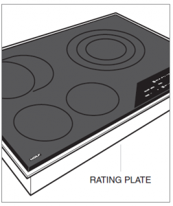
Important product information, including the model and serial number, are listed on the product rating plate. The rating plate is located on the bottom of the cooktop. Refer
to the illustrations below. If service is necessary, contact Wolf Factory CertifiedService with the model and serial number. For the name of the nearest Wolf Factory Certified Service or for questions regarding the installation, visit the Product Support section of our website, wolfappliance.com, or call Wolf Customer Care at 800-222-7820.


Specifications
Installation Requirements
A minimum 2″ (51) is required from the bottom of the cooktop to combustible materials. Clearance is required for the conduit located at the right rear of induction and electric cooktops. Refer to the illustration below for dimensions. Refer to the illustrations on pages 6–8 for additional minimum clearances. Installation dimensions are the same for
induction and electric cooktops of the same width.

Failure to locate the cooktop without proper clearances will result in a fire hazard.

FLUSH INSTALLATION
Contemporary induction and electric cooktops can be mounted flush with the top of the countertop or as a frameless standard installation sitting on top of the countertop
surface. If the cooktop is to be mounted flush with the countertop, a recessed area surrounding the cooktop cutout must be provided. An installation kit and instructions required for a flush installation are provided with the Contemporary cooktop.

A flush installation is intended for granite, solid surface, or stone countertop surfaces only.
MULTIPLE COOKTOPS
When multiple cooktops or modules are installed side by side, the countertop cutout width is determined by adding the width of each unit, then subtracting 1″ (25). Refer to the
illustration below.
IMPORTANT NOTE:
Contemporary induction and electric cooktops are not designed to be installed in combination with other cooktops.

Electrical Requirements
Installation must comply with all applicable electrical codes. Locate the electrical supply as shown in the illustrations on the following pages. A separate circuit servicing only
this appliance is required. A ground fault circuit interrupter (GFCI) is not recommended and may cause interruption of operation. When multiple cooktops are installed side by side, each unit must have its own separate recommended electrical circuit.
ELECTRICAL REQUIREMENTS
INDUCTION
Electrical Supply 3-wire, 240/208 VAC, 60 Hz
Conduit flexible 4′ (1.2 m)
ELECTRIC
Electrical Supply 3-wire, 240 VAC, 60 Hz
Conduit flexible 4′ (1.2 m)
SERVICE
15″ Induction/Electric 20 amp dedicated circuit
24″ Induction 30 amp dedicated circuit
30″ Induction/Electric 40 amp dedicated circuit
36″ Induction/Electric 50 amp dedicated circuit


15″ Cooktop
STANDARD INSTALLATION


NOTE: Shaded area above countertop indicates minimum clearance to combustible surfaces,
combustible materials cannot be located within this area.
24″, 30″, and 36″ Cooktops
STANDARD INSTALLATION
COUNTERTOP CUTOUT


SIDE VIEW FRONT VIEW
NOTE: Shaded area above countertop indicates minimum clearance to combustible surfaces, combustible materials cannot be located within this area.
Electrical supply location only applies to installations with built-in oven.
24″, 30″, and 36″ Cooktops
FLUSH INSTALLATION
COUNTERTOP CUTOUT


SIDE VIEW FRONT VIEW
NOTE: Shaded area above countertop indicates minimum clearance to combustible surfaces, combustible materials cannot be located within this area.
Electrical supply location only applies to installations with built-in oven. Outside corner radius 7/16″ (11).
CUTOUT WIDTH W A
24″ Induction 22 1/8″ (562) 23 3/4″ (603)
30″ Induction/Electric 29″ (737) 30 1/8″ (765)
36″ Induction/Electric 35″ (889) 36 1/8″ (918)
Flush Installation
To ensure a proper installation, a template for the countertop cutout should be created using the cooktop glass.
ROUTING OPTION
For this installation, a recessed area surrounding the countertop cutout is required. Fabrication of the recessed area bmust take place before the countertop is installed.
This option is not recommended for countertops with a molded backsplash.
CLEAT OPTION
For this installation, the countertop cutout is the same size as the outer edge of the cooktop glass. Attach L-shaped cleats to the perimeter of the countertop
cutout. The top edge of the cleat cannot be wider than 7/8″ (22) and is attached 5/16″ (8) below the surface of the countertop. Refer to the illustration below. Attach the
cleats to the countertop. Consult a countertop supplier for proper methods of attachment.
Support cleats

Cooktop Installation
Remove the cooktop and components from the shipping package and recycle packing materials.
- Lower the cooktop into the countertop cutout. Center the cooktop in the opening with the front edge aligned parallel to the front edge of the countertop. Using a
pencil, outline the rear edge of the cooktop on the countertop. Remove the cooktop. - Apply the foam strip to the perimeter of the countertop opening. Refer to the illustration below. Do not seal the cooktop to the countertop.
- Insert the cooktop into the opening. Verify the cooktop is aligned with the front edge of the countertop.
- Attach the provided brackets to the bottom of the unit. Insert the 3 1/2″ (89) clamping screws into the brackets. Use a screwdriver to tighten the clamping screws
against the bottom of the countertop. Do not overtighten screws. Refer to the illustration below.

Troubleshooting
IMPORTANT NOTE: If the cooktop does not operate properly, follow these troubleshooting steps:
- Verify electrical power is supplied to the cooktop.
- If the cooktop does not operate properly, contact Wolf Factory Certified Service. Do not attempt to repair the cooktop. Wolf is not responsible for service required to
correct a faulty installation.
Sub-Zero, Sub-Zero & Design, Sub-Zero & Snowflake Design, Dual Refrigeration, The Living Kitchen, Great American Kitchens The Fine Art of Kitchen Design, Wolf, Wolf & Design, Wolf Gourmet, W & Design, red colored knobs, Cove, and Cove & Design are registered trademarks and service marks of Sub-Zero Group, Inc. and its subsidiaries.
All other trademarks are property of their respective owners in the United States and other countries.