D-Link Unified AC Tri Band PoE Access Installation Guide
D-Link Unified AC Tri Band PoE Access Installation Guide

About This Guide
This installation guide provides basic instructions for installing the DWL-7620AP Unified AC Tri Band PoE Access on your network. For additional information about
how to use the access point, please see the User Manual, which is available on the CD included in this package or from the D-Link support website.
System Requirements
– CD-ROM drive
– Windows®, Macintosh®, or Linux-based operating system
– An available Ethernet port
– Internet Explorer 11, Safari 7, Firefox 28,
Google Chrome 33 or higher
Unpacking the Product
Open the shipping carton and carefully unpack its contents. Please consult the packing list below to make sure all items are present and undamaged. If any item is missing or damaged, please contact your local D-Link reseller for replacement.
— DWL-7620AP
— Mounting ring
— Console cable*
— CD-ROM
— Ceiling bracket (3 sets, sizes are 9/16″, 14/16″, and 1 1/2″)
*The console cable is an optional accessory and not included in the package in Armenia, Azerbaijan, Belarus, Georgia, Israel, Kaliningrad, Kazakhstan, Kyrgyzstan, Latvia, Lithuania, Moldova, Mongolia, Russia, Turkey, Turkmenistan, Ukraine, and Uzbekistan. If a cable is required, please contact your reseller to order it (Model: ACS-AP-CONSOLE).
Optional Accessories
– PoE Injector (Model: DPE-301GI)
Note: These accessories are not included in the package. If any of these items are required, please contact your reseller to order it.
Hardware Overview
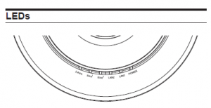

Figure 1. DWL-7620AP LEDs
| POWER | When this LED is red, the access point is booting up. When it is green, it is ready for use. |
| LAN1/LAN2 | When this LED is lit, the device’s Ethernet port is connected to an active router or switch. The light will flash when data is being transmitted through the port. |
| 2.4GHz/5GHz | When the LED is lit, the access point’s wireless radio is enabled. It will flash when data is being transmitted via wireless. |


Installation
Power on the Access Point
To power on the DWL-7620AP, you can use one of the following methods:
- Connect the supplied power adapter.
OR - Plug one end of an Ethernet cable into the LAN 1 port of the DWL-7620AP and the other end into a port on a PoE switch or injector.
To set up and manage the DWL-7620AP, use one of the following methods:
- Manage the access point from the computer: Connect the access point and your computer directly via a straight-through Ethernet cable. Ensure
your computer is configured with a static IP address in the 10.90.90.0/24 subnet. Launch a web browser, type the default IP address of the access point
(http://10.90.90.91), then press Enter. To log in, use the default login information: Username: admin Password: admin - Manage the access point from the computer via the switch or router: Connect the access point and your computer to the same switch or router. If the access point did not acquire an IP address from a DHCP server on the network, enter 10.90.90.91 in the address field of your browser, which is the default IP address of the access
point. If you used a DHCP server on your network to automatically configure network information for the access point, enter the new IP address of the access point into the web browser. To log in, use the default login information: Username: admin Password: admin - Manage the access point from the computer via the Unified Wireless Switch or Wireless Controller: Connect the access point to a Unified Wireless Switch or Wireless Controller. Connect your computer to the same network as that of the Unified Wireless Switch or Wireless Controller. Log in to the Unified Wireless Switch web
administration page or Wireless Controller web administration page. For the default login information please see Unified Wireless Switch user manual or Wireless Controller user manual.


Mounting Options
You can mount the DWL-7620AP access point on any of the following types of surfaces:
- Solid surface wall or ceiling
- Tabletop
Cable Requirement
Use a CAT 5 cable with an even sheath. The Ethernet ports on the DWL-7620AP access point cannot accept a CAT 5 cable that has an uneven sheath; the RJ-45
connector on the cable will not fit properly into the receptacle on the access point.
Wall Installation Recommendations
If you plan to install the DWL-7620AP on a wall or other vertical surfaces, orient the top of the access point (the side with the LEDs) toward the intended coverage area. The
radio antennas transmit through the top of the access point but not through the bottom (where the bracket is).
Warning:
The DWL-7620AP is designed to receive PoE power only from an 802.3atcompliant source, or from a D-Link-approved power adapter. Connecting an access point
to a Power over Ethernet (PoE) device that is not approved by D-Link can damage the equipment.
Warning:
This product is to be connected only to indoor PoE networks with no outdoor cable routing.
Mounting Using Anchor Screws
Installation
- Place the plastic wall mounting ring on a wall or ceiling. Mark the points where you will insert the screws, then remove the mounting ring.
- Drill holes in the marked points and insert the plastic wall anchors.
- Use the supplied screws to attach the mounting ring to the wall.
- Plug the CAT 5 cable into the LAN port on the access point.
- To attach the access point to the mounting ring, first locate the right side of the access point that has a small lock symbol on it, and make sure to line up
this side with the side of the mounting ring that has Open – Lock written on it. - Twist clockwise to lock the access point onto the ring. The lock symbol on the access point must point directly to the Close text on the mounting ring.


Mounting Using Ceiling Bracket
Installation
- Clip two ceiling brackets on the ceiling panels. Make sure both bracket are parallel
- Use the provided screws to attach the mounting ring to the ceiling bracket.
- Plug the CAT 5 cable into the LAN port on the access point.
- Place the DWL-7620AP onto the mounting ring and rotate the device clockwise to lock it in position.


Regulatory Statements
ErP Power Usage
This device is an Energy Related Product (ErP) with High Network Availability (HiNA), and automatically switches to a power-saving Network Standby mode within 1 minute of no packets being transmitted. It can also be turned off through a power switch to save energy when it is not needed.
Network Standby: 6.3792 watts Switched Off: 0.0665 watts
Federal Communication Commission Interference Statement
This equipment has been tested and found to comply with the limits for a Class B digital device, pursuant to Part 15 of the FCC Rules. These limits are designed to provide reasonable protection against harmful interference in a residential installation. This equipment generates, uses and can radiate radio frequency energy and, if not installed and used in accordance with the instructions, may cause harmful interference to radio communications. However, there is no guarantee that interference will not occur in a particular installation. If this equipment does cause harmful interference to radio or television reception, which can be determined by turning the equipment off and on, the user is encouraged to try to correct the interference by one of the following measures:
— Reorient or relocate the receiving antenna.
— Increase the separation between the equipment and receiver.
— Connect the equipment into an outlet on a circuit different from that to which the receiver is connected.
— Consult the dealer or an experienced radio/TV technician for help.
Non-modifications Statement:
Any changes or modifications not expressly approved by the party responsible for compliance could void the user’s authority to operate this equipment
Caution:
This device complies with Part 15 of the FCC Rules. Operation is subject to the following two conditions:
(1) This device may not cause harmful interference, and (2) this device must accept any interference received, including interference that may cause undesired operation.
This device and its antenna(s) must not be co-located or operating in conjunction with any other antenna or transmitter except in accordance with FCC multi-transmitter product procedures. For product available in the USA/Canada market, only channel 1~11 can be operated. Selection of other channels is not possible
Note:
The country code selection is for non-USA models only and is not available to all USA models. Per FCC regulations, all WiFi product marketed in the USA must be fixed to USA operational channels only.
RF Frequency Requirements
This device is for indoor use only when using all channels in the 5.150 GHz – 5.250 GHz, 5.250 GHz – 5.350 GHz, 5.470 GHz – 5.725 GHz, 5.725 GHz – 5.850 GHz
frequency range. High power radars are allocated as primary users of the 5.150 GHz – 5.250 GHz, 5.250 GHz – 5.350 GHz, 5.470 GHz – 5.725 GHz, 5.725 GHz – 5.850 GHz
bands. These radar stations can cause interference with and/or damage this device. This device will not operate on channels which overlap the 5600-5650 MHz band.
It is restricted to indoor environments only.
IMPORTANT NOTICE:
FCC Radiation Exposure Statement
This equipment complies with FCC radiation exposure limits set forth for an uncontrolled environment. This equipment should be installed and operated with minimum distance 25 cm between the radiator and your body.
Innovation, Science and Economic Development Canada (ISED) Statement:
Innovation, Science and Economic Development Canada (ISED) Statement:
This device complies with ISED licence-exempt RSS standard(s). Operation is subject to the following two conditions:
(1) this device may not cause interference, and
(2) this device must accept any interference, including interference that may cause undesired operation of the device.
(i) the device for operation in the band 5150-5250 MHz is only for indoor use to reduce the potential for harmful interference to co-channel mobile satellite systems;
(ii) the maximum antenna gain permitted for devices in the bands 5250-5350 MHz and 5470- 5725 MHz shall comply with the e.i.r.p. limit
(iii) the maximum antenna gain permitted for devices in the band 5725-5825 MHz shall comply with the e.i.r.p. limits specified for point-to-point and non point-to-point operation as appropriate.
(iv) the worst-case tilt angle(s) necessary to remain compliant with the e.i.r.p. elevation mask requirement set forth in Section 6.2.2(3) shall be clearly indicated.
(v) users should also be advised that high-power radars are allocated as primary users (i.e. priority
users) of the bands 5250-5350 MHz and 5650-5850 MHz and that these radars could cause
interference and/or damage to LE-LAN devices.
| Frequency Band(s) | Max. Output Power (EIRP) Max. Output Power de Salida Potenza max. Output Max. Output Power | |
| 5 G |
5.15 – 5.25 GHz | 1 W |
| 5.725 – 5.850 GHz | 1 W | |
| 2.4 G | 2.4 – 2.4835 GHz | 100 mW |
SAFETY INSTRUCTIONS
The following general safety guidelines are provided to help ensure your own personal safety and protect your
product from potential damage. Remember to consult the product user instructions for more details.
- Static electricity can be harmful to electronic components. Discharge static electricity from your body (i.e. touching grounded bare metal) before touching the product.
- Do not attempt to service the product and never disassemble the product. For some products with a user replaceable battery, please read and follow the instructions in the user manual.
- Do not spill food or liquid on your product and never push any objects into the openings of your product.
- Do not use this product near water, areas with high humidity, or condensation unless the product is specifically rated for outdoor application.
- Keep the product away from radiators and other heat sources.
- Always unplug the product from mains power before cleaning and use a dry lint free cloth only.
Disposing of and Recycling Your Product

D-Link and the Environment
At D-Link, we understand and are committed to reducing any impact our operations and products may have on the environment. To minimise this impact D-Link designs and builds its products to be as environmentally friendly as possible, by using recyclable, low toxic materials in both products and packaging. D-Link recommends that you always switch off or unplug your D-Link products when they are not in use. By doing so you will help to save energy and reduce CO2 emissions. To learn more about our environmentally responsible products and packaging please visit www.dlinkgreen.com.