Makita DCS551 Cordless Metal Cutter Instruction Manual
makita DCS551 Cordless Metal Cutter
Instruction Manual


Explanation of general view
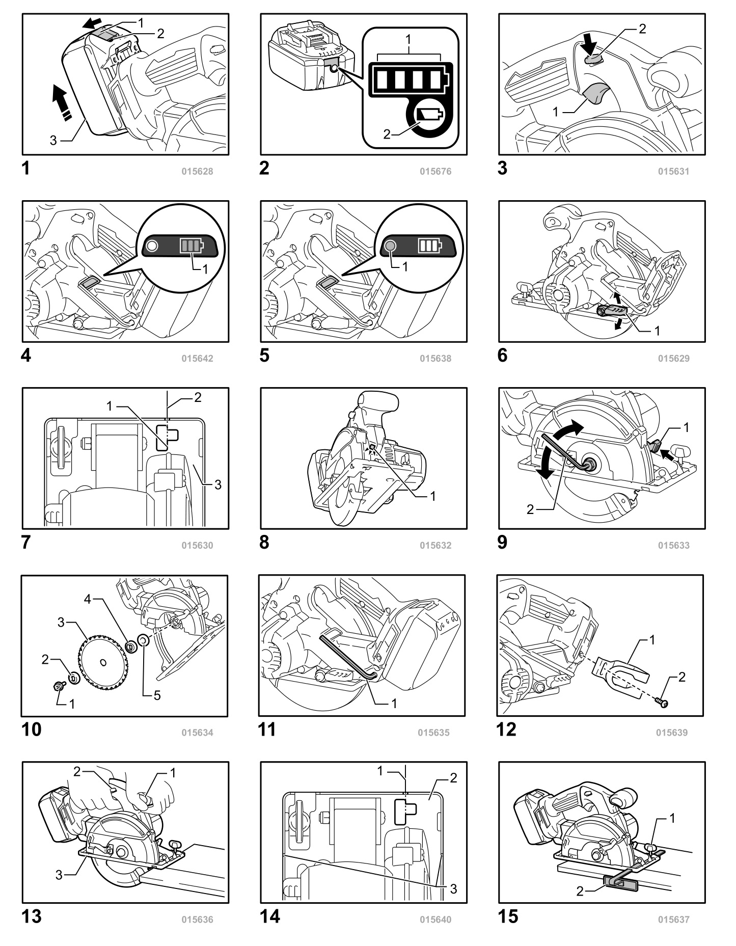
1-1. Button
1-2. Red indicator
1-3. Battery cartridge
2-1. Indicator lamps
2-2. Check button
3-1. Switch trigger
3-2. Lock-off lever
4-1. Battery indicator
5-1. Mode indicator
6-1. Lever
7-1. Alignment line
7-2. Cutting line
7-3. Base
8-1. Lamp
9-1. Shaft lock
9-2. Hex wrench
10-1. Hex bolt
10-2. Outer flange
10-3. Saw blade
10-4. Inner flange
10-5. Cup washer
11-1. Hex wrench
12-1. Hook
12-2. Screw
13-1. Front grip
13-2. Rear handle
13-3. Base
14-1. Cutting line
14-2. Base
14-3. Sight grooves
15-1. Clamp screw
15-2. Rip fence (Guide rule)
SPECIFICATIONS

- Due to our continuing program of research and development, the specifications herein are subject to change without notice.
- Specifications and battery cartridge may differ from country to country.
- Weight, with battery cartridge, according to EPTA-Procedure 01/2003
Intended use
The tool is intended for cutting in mild steel.
Noise
The typical A-weighted noise level determined according to EN60745:
Sound pressure level (LpA) : 78 dB (A)
Uncertainty (K) : 3 dB (A
The noise level under working may exceed 80 dB (A).
Wear ear protection
Vibration
The vibration total value (tri-axial vector sum) determined according to EN60745:
Work mode : cutting metal
Vibration emission (ah,M) : 2.5 m/s2 or less
Uncertainty (K) : 1.5 m/s2
- The declared vibration emission value has been measured in accordance with the standard test method and may be used for comparing one tool with another.
- The declared vibration emission value may also be used in a preliminary assessment of exposure.

- The vibration emission during actual use of the power tool can differ from the declared emission value depending on the ways in which the tool is used.
- Be sure to identify safety measures to protect the operator that are based on an estimation of exposure in the actual conditions of use (taking account of all parts of the operating cycle such as the times when the tool is switched off and when it is running idle in addition to the trigger time).
For European countries only
EC Declaration of Conformity
Makita declares that the following Machine(s):
Designation of Machine:
Cordless Metal Cutter
Model No./ Type: DCS551
Conforms to the following European Directives:
2006/42/EC
They are manufactured in accordance with the following standard or standardized documents:
EN60745
The technical file in accordance with 2006/42/EC is available from:
Makita, Jan-Baptist Vinkstraat 2, 3070, Belgium
23.10.2014

Yasushi Fukaya
Director
Makita, Jan-Baptist Vinkstraat 2, 3070, Belgium
General Power Tool Safety Warnings
Save all warnings and instructions for future reference.
CORDLESS METAL CUTTER SAFETY WARNINGS
Cutting procedures
- Do not reach underneath the workpiece. The guard cannot protect you from the blade below the workpiece.
- Adjust the cutting depth to the thickness of the workpiece. Less than a full tooth of the blade teeth should be visible below the workpiece.
- Never hold piece being cut in your hands or across your leg. Secure the workpiece to a stable platform. It is important to support the work properly to minimize body exposure, blade binding, or loss of control.
- Hold the power tool by insulated gripping surfaces only, when performing an operation where the cutting tool may contact hidden wiring. Contact with a “live” wire will also make exposed metal parts of the power tool “live” and could give the operator an electric shock.
- When ripping, always use a rip fence or straight edge guide. This improves the accuracy of cut and reduces the chance of blade binding.
- Always use blades with correct size and shape (diamond versus round) of arbour holes. Blades that do not match the mounting hardware of the tool will run eccentrically, causing loss of control.
- Never use damaged or incorrect blade
washers or bolt. The blade washers and bolt were specially designed for your tool, for optimum performance and safety of operation.
Kickback causes and related warnings
− Kickback is a sudden reaction to a pinched, bound or misaligned blade, causing an uncontrolled tool to lift up and out of the workpiece toward the operator.
− When the blade is pinched or bound tightly by the kerf closing down, the blade stalls and the motor reaction drives the unit rapidly back toward the operator.
− If the blade becomes twisted or misaligned in the cut, the teeth at the back edge of the blade can dig into the top surface of the workpiece causing the blade to climb out of the kerf and jump back toward the operator.
Kickback is the result of tool misuse and/or incorrect operating procedures or conditions and can be avoided by taking proper precautions as given below. - Maintain a firm grip with both hands on the tool and position your arms to resist kickback forces. Position your body to either side of the blade, but not in line with the blade. Kickback could cause the tool to jump backwards, but kickback forces can be controlled by the operator, if proper precautions are taken.
- When blade is binding, or when interrupting a cut for any reason, release the trigger and hold the tool motionless in the material until the blade comes to a complete stop. Never attempt to remove the tool from the work or pull the tool backward while the blade is in motion or KICKBACK may occur. Investigate and take corrective actions to eliminate the cause of blade binding.
- When restarting a tool in the workpiece, center the blade in the kerf and check that blade teeth are not engaged into the material. If blade is binding, it may walk up or kickback from the workpiece as the tool is restarted.
- Support large panels to minimise the risk of blade pinching and kickback. Large panels tend to sag under their own weight. Supports must be placed under the panel on both sides, near the line of cut and near the edge of the panel.
- Do not use dull or damaged blades. Unsharpened or improperly set blades produce narrow kerf causing excessive friction, blade binding and kickback.
- Blade depth and bevel adjusting locking levers must be tight and secure before making cut. If blade adjustment shifts while cutting, it may cause binding and kickback.
- Use extra caution when making a “plunge cut” into
existing walls or other blind areas. The protruding blade may cut objects that can cause kickback. For plunge cuts, retract lower guard using retracting handle.
Lower guard function
- Check lower guard for proper closing before each use. Do not operate the tool if lower guard does not move freely and close instantly. Never clamp or tie the lower guard into the open position. If tool is accidentally dropped, lower guard may be bent. Raise the lower guard with the retracting lever and make sure it moves freely and does not touch the blade or any other part, in all angles and depths of cut.
- Check the operation and condition of the lower guard spring. If the guard and the spring are not operating properly, they must be serviced before use. Lower guard may operate sluggishly due to damaged parts, gummy deposits, or a buildup of debris.
- Lower guard may be retracted manually only for special cuts such as “plunge cuts” and “compound cuts”. Raise lower guard by retracting handle and as soon as blade enters the material, the lower guard must be released. For all other sawing, the lower guard should operate automatically.
- Always observe that the lower guard is covering the blade before placing tool down on bench or floor. An unprotected, coasting blade will cause the tool to walk backwards, cutting whatever is in its path. Be aware of the time it takes for the blade to stop after switch is released.
- To check lower guard, open lower guard by
hand, then release and watch guard closure.
Also check to see that retracting handle does
not touch tool housing. Leaving blade exposed is VERY DANGEROUS and can lead to serious personal injury.
Additional safety warnings
- Do not stop the blades by lateral pressure on the blade.
- DANGER:
Do not attempt to remove cut material when blade is moving.
CAUTION: Blades coast after turn off. - Place the wider portion of the tool base on that part of the workpiece which is solidly supported, not on the section that will fall off when the cut is made.
- Never attempt to make a cut with the tool held upside down in a vise. This is extremely dangerous and can lead to serious accidents.
- Wear safety goggles and hearing protection during operation.
- Do not use any abrasive wheels.
- Only use the blade with the diameter that is
marked on the tool or specified in the manual. Use of an incorrectly sized blade may affect the proper guarding of the blade or guard operation which could result in serious personal injury.
SAVE THESE INSTRUCTIONS.
DO NOT let comfort or familiarity with product (gained from repeated use) replace strict adherence to safety rules for the subject product. MISUSE or failure to follow the safety rules stated in this instruction manual may cause serious personal injury.
IMPORTANT SAFETY INSTRUCTIONS
FOR BATTERY CARTRIDGE
- Before using battery cartridge, read all instructions and cautionary markings on (1) battery charger, (2) battery, and (3) product using battery.
- Do not disassemble battery cartridge.
- If operating time has become excessively shorter, stop operating immediately. It may result in a risk of overheating, possible burns and even an explosion.
- If electrolyte gets into your eyes, rinse them out with clear water and seek medical attention right away. It may result in loss of your eyesight.
- Do not short the battery cartridge:
(1) Do not touch the terminals with any conductive material.
(2) Avoid storing battery cartridge in a container with other metal objects such as nails, coins, etc.
(3) Do not expose battery cartridge to water or rain.
A battery short can cause a large current flow, overheating, possible burns and even a breakdown. - Do not store the tool and battery cartridge in locations where the temperature may reach or exceed 50 ゚ C (122 ゚ F).
- Do not incinerate the battery cartridge even if it is severely damaged or is completely worn out. The battery cartridge can explode in a fire.
- Be careful not to drop or strike battery.
- Do not use a damaged battery.
- Follow your local regulations relating to disposal of battery.
SAVE THESE INSTRUCTIONS.
Use of non-genuine Makita batteries, or batteries that have been altered, may result in the battery bursting causing fires, personal injury and damage. It will also void the Makita warranty for the Makita tool and charger.
Tips for maintaining maximum battery life
- Charge the battery cartridge before completely discharged.
Always stop tool operation and charge the battery cartridge when you notice less tool power. - Never recharge a fully charged battery cartridge. Overcharging shortens the battery service life.
- Charge the battery cartridge with room temperature at 10 ゚ C – 40 ゚ C (50 ゚ F – 104 ゚ F). Let a hot battery cartridge cool down before charging it.
- Charge the battery cartridge if you do not use it for a long period (more than six months).
FUNCTIONAL DESCRIPTION
- Always be sure that the tool is switched off and the battery cartridge is removed before adjusting or checking function on the tool.
Installing or removing battery cartridge
Fig.1
- Always switch off the tool before installing or removing of the battery cartridge.
- Hold the tool and the battery cartridge firmly
when installing or removing battery cartridge.
Failure to hold the tool and the battery cartridge firmly may cause them to slip off your hands and result in damage to the tool and battery cartridge and a personal injury.
To remove the battery cartridge, slide it from the tool while sliding the button on the front of the cartridge.
To install the battery cartridge, align the tongue on the battery cartridge with the groove in the housing and slip it into place. Insert it all the way until it locks in place with a little click. If you can see the red indicator on the upper side of the button, it is not locked completely.
- Always install the battery cartridge fully until the red indicator cannot be seen. If not, it may accidentally fall out of the tool, causing injury to you or someone around you.
- Do not install the battery cartridge forcibly. If the cartridge does not slide in easily, it is not being inserted correctly.
Indicating the remaining battery capacity
(Only for battery cartridges with “B” at the end of the model number.)
Fig.2
Press the check button on the battery cartridge to indicate the remaining battery capacity. The indicator lamps light up for few seconds.

NOTE:
- Depending on the conditions of use and the ambient temperature, the indication may differ slightly from the actual capacity.
Switch action
- For your safety, this tool is equipped with lock-off lever which prevents the tool from unintended starting. NEVER use the tool if it runs when you simply pull the switch trigger without pressing the lock-off lever. Return tool to a MAKITA service center for proper repairs BEFORE further usage.
- NEVER tape down or defeat purpose and function of lock-off lever.
- Before installing the battery cartridge into the tool, always check to see that the switch trigger actuates properly and returns to the “OFF” position when released.
- Do not pull the switch trigger hard without pressing the lock-off lever. This can cause switch breakage.
Fig.3
To prevent the switch trigger from being accidentally pulled, a lock-off lever is provided. To start the tool, press the lock-off lever and pull the switch trigger. Release the switch trigger to stop.
Indicating remaining battery capacity
(Country specific)
Fig.4
When you turn the tool on, the battery indicator shows the remaining battery capacity.
The remaining battery capacity is shown as the following table.

Automatic speed change function
Fig.5

This tool has “high speed mode” and “high torque mode”. It automatically changes operation mode depending on the work load. When mode indicator lights up during operation, the tool is in high torque mode.
Tool / battery protection system
The tool is equipped with a tool/battery protection system. This system automatically cuts off power to the motor to extend tool and battery life.
The tool will automatically stop during operation if the tool or battery are placed under one of the following conditions. In some conditions, the indicator lights up.
Overload protection
When the tool is operated in a manner that causes it to draw an abnormally high current, the tool automatically stops without any indications. In this situation, turn the tool off and stop the application that caused the tool to become overloaded. Then turn the tool on to restart.
Overheat protection for tool
When the tool is overheated, the tool stops automatically and the battery indicator shows following state. In this situation, let the tool cool before turning the tool on again.

Releasing protection lock
When the protection system works repeatedly, the tool is locked and the battery indicator shows the following state.

In this situation, the tool does not start even if turning the tool off and on. To release the protection lock, remove the battery, set it to the battery charger and wait until the charging finishes.
Adjusting depth of cut
Fig.6
- After adjusting the depth of cut, always tighten the lever securely.
Loosen the lever on the side of the rear handle and move the base up or down. At the desired depth of cut, secure the base by tightening the lever.
For cleaner, safer cuts, set cut depth so that no more than one blade tooth projects below workpiece. Using proper cut depth helps to reduce potential for dangerous KICKBACKS which can cause personal injury.
Sighting
Fig.7
Place the alignment line of the base on your intended cutting line on the workpiece.
Lighting the lamp
- Do not look in the lamp or see the source of light directly.
Fig.8
Only to turn on the lamp, pull the switch trigger without pressing the lock-off lever. To turn on the lamp and run the tool, press the lock-off lever and pull the switch trigger with the lock-off lever being pressed. The lamp keeps on lighting while the switch trigger is being pulled. The lamp goes out 10 -15 seconds after releasing the trigger.
NOTE:
- Use a cotton stick to wipe the dirt off the lens of lamp. Be careful not to scratch the lens of lamp, or it may lower the illumination.
- Do not use gasoline, thinner or the like to clean the lens of lamp. Using such substances will damage the lens.
ASSEMBLY
- Always be sure that the tool is switched off and the battery cartridge is removed before carrying out any work on the tool.
Removing or installing blade
- Be sure the blade is installed with teeth pointing up at the front of the tool.
- Use only the Makita wrench to install or remove the blade.
Fig.9
To remove the blade, press the shaft lock so that the blade cannot revolve and use the hex wrench to loosen the hex bolt counterclockwise. Then remove the hex bolt, outer flange and blade.
Fig.10
To install the blade, follow the removal procedure in reverse. BE SURE TO TIGHTEN THE HEX BOLT CLOCKWISE SECURELY.
When changing blade, make sure to also clean the upper and lower blade guards of accumulated metal chips as discussed in the Maintenance section. Such efforts do not replace the need to check lower guard operation before each use.
Hex wrench storage
Fig.11
When not in use, store the hex wrench as shown in the figure to keep it from being lost.
Installing or removing hook
- Never hang the tool on a waist belt or like. Dangerous accidental cut may result.
- Never hook the tool at high location or on potentially unstable surface.
Fig.12
The hook can be installed on the motor side of the tool as illustrated. To install the hook, insert it into a groove on the tool housing, and secure it with the screw. To remove the hook, loosen the screw and take it off.
OPERATION
- Always insert the battery cartridge all the way until it locks in place. If you can see the red indicator on the upper side of the button, it is not locked completely. Insert it fully until the red indicator cannot be seen. If not, it may accidentally fall out of the tool, causing injury to you or someone around you.
- Be sure to move the tool forward in a straight line gently. Forcing or twisting the tool will result in overheating the motor and dangerous kickback, possibly causing severe injury.
- If the tool is operated continuously until the battery cartridge has discharged, allow the tool to rest for 15 minutes before proceeding with a fresh battery.
- Never twist or force the tool in the cut. This may cause motor overload and/or a dangerous kickback, resulting in serious injury to the operator.
- Always wear eye protection or goggle before operation.
Fig.13
Hold the tool firmly. The tool is provided with both a front grip and rear handle. Use both to best grasp the tool. If both hands are holding the tool, they cannot be cut by the blade. Set the base on the workpiece to be cut without the blade making any contact. Then turn the tool on and wait until the blade attains full speed. Now simply move the tool forward over the workpiece surface, keeping it flat and advancing smoothly until the cutting is completed.
To get clean cuts, keep your cutting line straight and your speed of advance uniform. If the cut fails to properly follow your intended cut line, do not attempt to turn or force the tool back to the cut line. Doing so may bind the blade and lead to dangerous kickback and possible serious injury. Release switch, wait for blade to stop and then withdraw tool. Realign tool on new cut line, and start cut again. Attempt to avoid positioning which exposes operator to chips and particles being ejected from the tool. Use eye protection to help avoid injury.
Fig.14
The sight grooves in the base makes it easy to check the distance between the front edge of the blade and the workpiece whenever the blade is set to the maximum depth of cut.
- Do not use a deformed or cracked blade. Replace it with a new one.
- Do not stack materials when cutting them.
- Do not cut hardened steel, wood, plastics, concrete, tile, etc. Cut only mild steel, aluminum and stainless steel with a suitable saw blade.
- Do not touch the blade, workpiece or cutting chips with your bare hand immediately after cutting, they may be extremely hot and could burn your skin.
- Always use the blades appropriate for your job. The use of inappropriate blades may cause a poor cutting performance and/or present a risk of personal injury.
Rip fence (Guide rule) (optional accessory)
Fig.15
The handy rip fence allows you to do extra-accurate straight cuts. Simply slide the rip fence up snugly against the side of the workpiece and secure it in position with the clamp screw on the front of the base. It also makes repeated cuts of uniform width possible.
MAINTENANCE
- Always be sure that the tool is switched off and the battery cartridge is removed before attempting to perform inspection or maintenance.
- Clean out the upper and lower guards to ensure there is no accumulated metal chips which may impede the operation of the lower guarding system. A dirty guarding system may limit the proper operation which could result in serious personal injury. When using compressed air to blow metal chips out of the guards, wear a proper eye and breathing protection.
- Never use gasoline, benzine, thinner, alcohol or the like. Discoloration, deformation or cracks may result.
Inspecting blade
- Check the blade carefully for cracks or damage before and after each use. Replace a cracked or damaged blade immediately.
- Continuing to use a dull blade may cause a dangerous kickback and/or motor overload. Replace with a new blade as soon as it no longer cuts effectively.
- Blades for metal cutter cannot be re-sharpened.
To maintain product SAFETY and RELIABILITY, repairs, any other maintenance or adjustment should be performed by Makita Authorized Service Centers, always using Makita replacement parts.
OPTIONAL ACCESSORIES
- These accessories or attachments are recommended for use with your Makita tool specified in this manual. The use of any other accessories or attachments might present a risk of injury to persons. Only use accessory or attachment for its stated purpose.
If you need any assistance for more details regarding these accessories, ask your local Makita Service Center.
- Carbide-tipped blades
- Rip fence (Guide rule)
- Thumb screw M5 x 20
- Hook
- Hex wrench 5
- Safety goggle
- Makita genuine battery and charger
NOTE:
- Some items in the list may be included in the tool package as standard accessories. They may differ from country to country.
Makita Jan-Baptist Vinkstraat 2, 3070, Belgium
Makita Corporation Anjo, Aichi, Japan