Honeywell 40003916-003 Replacement Powerhead for V4073A Mid-Position Valves Installation Guide

Powerhead for V4073A
Mid-Position Valves

INSTALLATION INSTRUCTIONS

APPLICATIONS
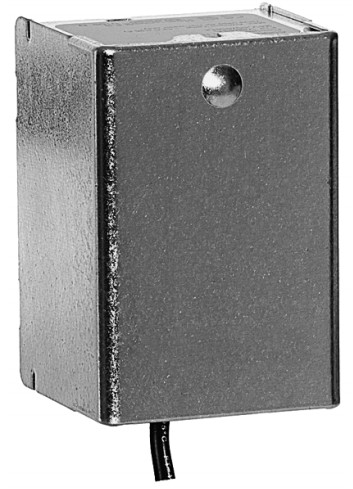
The 40003916 replacement heads are for field replacement of heads in Resideo V4073 mid-position valves. They can be used to replace the valve heads removable without draining the system and also valves that require draining the system. Ahead that does not require the system to be drained is identified by a small round bump on the cover and the “6” or higher suffix number after the OS number. Also, only two screws and two locating pegs are used to connect the head to the body.
For older style heads that require the system to be drained, an adaptor kit 40003918-007 must be used with the 40003916 head.
SPECIFICATIONS
Voltage: 230V ~ 50Hz
Power Consumption: 6W (0.04)
Lead Supplied: 1 metre
Operating Temperature Range: +5 to +88° C
Maximum Ambient Temperature: +52° C
| Zone Valve | Replacement Head Number |
Adaptor Kit Number |
| V407341005 | 40003916-003 | 40003918-007 |
| V407341039 | 40003916-003 | 40003918-007 |
| V407341054 | 40003916-003 | 40003918-007 |
| V407341062 | 40003916-003 | 40003918-007 |
| V407341088 | 40003916-003 | 40003918-007 |
INSTALLATION
REMOVING OLD STYLE HEAD FROM OLD STYLE BODY
It is not necessary to remove the valve body from the pipeline but the system must be drained of water before removing the old valve unless isolating valves have been fitted.
This product MUST be installed by a competent person.
The installation MUST conform to I.E.E. Regulations and with The Electricity at Work Regulations.


Fig. 1. Removing Cover

95C-10656-09
- Switch power supply OFF. Disconnect electrical leads noting the position and colour of each lead.
- Place the manual operating lever in the “MAN. OPEN” position. (See Fig. 1A.)
- Remove cover. (See Fig. 1B.)
- Remove the four screws that secure the powerhead to the valve body and remove the powerhead and Oring. (See Fig. 2.)
V4073A incorporates a manual lever, the lever should normally be in the “AUTO” position, but can be moved to the “MAN. OPEN” position for system drain down and filling purposes only.

Fig. 2. Removing Powerheads

Fig. A. New style head; old style body (requires an adaptor kit)

Fig. 3. Installing Replacement Heads
INSTALLING REPLACEMENT HEAD ON OLD STYLE VALVE BODY (REQUIRES THE ADAPTOR KIT)
- Insert the new O-ring (supplied with the Adaptor Kit) into the circular slot on top of the valve body. (See Fig. 3A.)
- Place the adaptor on the valve body and secure it with the four hex-nut screws provided – ensuring that the three guide pins engage in their mating recesses.
- Place the manual operating lever of the replacement head in the “MAN. OPEN” position and fit the head onto the valve body assembly – ensuring that the
shaft seats correctly. - Secure the head to the valve body adaptor assembly with the two screws provided.
- Reconnect the wiring as shown in Fig. 4 or follow the steps in the section Relay Model Replacement.
REMOVING NEW STYLE HEAD FROM NEW STYLE VALVE BODY (OR OLD STYLE VALVE BODY WITH ADAPTOR)
NOTE: It is not necessary to drain the system if the new style valve body or old-style valve body with adaptor remains in the pipeline.
- Switch power supplies OFF. Disconnect electrical leads, carefully noting the position and color of each lead.
- Place the manual operating lever in the “MAN.
OPEN” position. (See Fig. 1A.) - Remove cover. (See Fig. 1B.) Remove the two screws that secure the head to the valve body assembly and remove the powerhead.
INSTALLING NEW STYLE HEAD ON NEW STYLE VALVE BODY ASSEMBLY (OR OLD STYLE BODY WITH ADAPTOR ATTACHED)
- Place the manual operating lever on the replacement head in the “MAN. OPEN” position and fit the head onto the valve body, ensuring that the shaft seats
correctly. (See Fig. 3B.) - Secure the head to the valve body with the two screws provided and replace the cover.
OPERATION AND CHECKOUT
Check the wiring and ensure the manual operating lever is in the “AUTO” position. With the time control switched ON, check the valve functions as follows:
- Switch the room thermostat OFF and set the cylinder thermostat to the maximum setting. The boiler and pump should switch ON and the flow pipe to the cylinder begins to warm up.
Set the cylinder thermostat to a minimum setting.
The boiler and pump should go OFF. - Set the cylinder thermostat to a minimum and the room thermostat to the maximum setting. The boiler and pump should switch ON. The valve will open to central heating and the radiators begin to warm up.
Set the room thermostat to a minimum.
The boiler and pump should go OFF.
However, it is a characteristic of the valve that it will remain in its last port of call and the motor will remain warm. - Set the room and cylinder thermostat to maximum.
Hot water should flow to both heating and hot water.
RESET BOTH THERMOSTATS TO DESIRED SETTINGS.
RELAY MODEL REPLACEMENT

Fig. 4. Wiring Diagram
When replacing the old 6 wire valve with relay, wire the new valve color-for-color apart from the Brown wire which is missing from the new valve.
ON SINGLE OUTPUT TIME SWITCHES
Omit Brown wire and reverse C&1 on the cylinder thermostat.
ON DOUBLE OUTPUT PROGRAMMERS
(i.e. separate switching outputs for Heating and Hot water circuits) Omit Brown wire and reverse C&1 on the cylinder thermostat.
- For Programmers capable of selecting heating only extra cable from the Grey wire on the valve to the HOT WATER OFF terminal on the programmer.
- For Programmers NOT capable of selecting heating only: This extra cable is NOT required and MUST NOT be included.
EXCEPT
- ON RANDALL 4033 PROGRAMMER
Remove wire that connects to cylinder thermostat 1 at junction box end and reconnect to orange wire connection of mid-position valve. Disconnect wire at
terminal 1 on the programmer, isolate and make safe.
Add link in programmer backplate between terminals 1 and 6.
NB. If the Randall 4033 has been used as a junction box, any wires going into terminal 1 should be removed and re-connected into a spare terminal connector. (Not supplied by Resideo.) - ON SANGAMO 410 FORM 1 PROGRAMMER
Follow instructions for Randall 4033, except on the Programmer base plate, disconnect the wire on terminal 3 and add a link between 3 and 6 on the base plate of pro- gram.
Whilst Resideo takes all practicable steps to design and manufacture its products to comply with the requirements of the Health and Safety at Work Act 1974, all products must be properly used and Purchasers are reminded that their obligations under the Act are to ensure that the installation and operation of such products at a place of work should be safe and without risk to them.
Resideo reserves the right at any time and without notice to change any product or information contained in this publication.
The wiring diagrams and installation instructions in this publication are provided for guidance purposes when installing recognized standard systems only. Any application of this product not shown here, or any deviation from these instructions, is neither recommended nor advised. Any such application or deviation should be referred to Resideo for technical assistance.
40003916-003 REPLACEMENT POWERHEAD FOR V4073A MID-POSITION VALVES
Manufacturer for European Region:
Pittway Sarl, Z.A. La Piece 4,
1180 Rolle, Switzerland
Country of origin: Hungary
95C-10656—09 M.S. Rev. 06-20 | Printed in the United States
Manufacturer for North and South America Region:
Resideo Technologies, Inc.
1985 Douglas Drive North, Golden Valley, MN 55422
1-800-468-1502

© 2020 Resideo Technologies, Inc. All rights reserved.
The Honeywell Home trademark is used under license from Honeywell International, Inc.