Honeywell VC series motorized valves User Guide
Honeywell VC series motorized valves User Guide


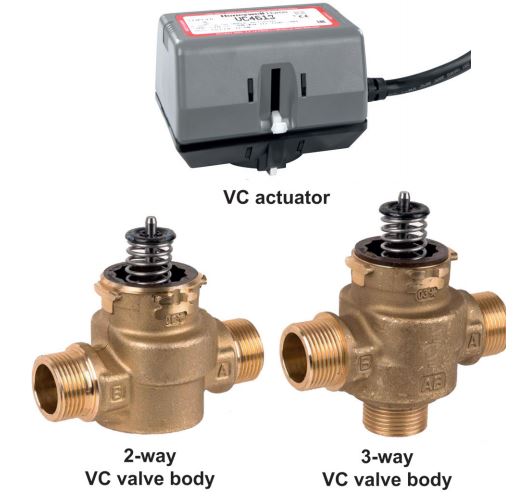
APPLICATION
VC Series balanced 2-position hydronic valves are used in domestic and small commercial heating and cooling applications to control the flow of hot and/or cold water.
They consist of an actuator, valve and a cartridge assembly. 2-way valves are designed for on-off zone control of domestic systems.
3-way valves can be piped for diverting applications in domestic central heating and/or cooling systems.
Both versions can be used to control individual fan coil, radiator, space heater or convector applications.
They can be controlled by a line voltage SPST or SPDT controller such as a room thermostat, aquastat or flow switch.
VC Series hydronic valves are designed to take advantage of sinusoidal valve actuator travel, and therefore operate silently and reduce water hammer.
Through internal logic the actuator only takes power while driving the valve to the commanded position.
The actuator head is removable without affecting the integrity of the water system.
All actuator versions are interchangeable with any valve body, offering the highest flexibility for installation in the field or boiler production line assembly, and maintenance.
The valve piston construction allows for port sealing that is independent of the differential pressure across the valve.
Flow through the 2-way valve can be in either direction, so the ports are not designated.
3-way valves are suitable for both diverting water from AB to A or B, and from A or B to AB.

SPECIAL FEATURES
- Rugged design
- High pressure differential up to 4 bar
- Control by a line voltage SPST or SPDT controller
- Minimal actuator power consumption
- Double insulated actuator
- Quick and easy replacement of moving parts
- Actuator head installation does not require draining of the system
- High flow rate capacity
TECHNICAL DATA

CONSTRUCTION

METHOD OF OPERATION
VC Series 2-position hydronic valves are used in domestic and small commercial applications to control the flow of hot and/or cold water. They consist of an actuator, valve and a cartridge assembly. All moving and sealing parts of the valve are constructed in the cartridge assembly. The ports are sealed with O-rings on the outer surface of the piston. When the valve stem is driven down to open port A the water will flow through the hollow piston to the other port. In case of a 3-way valve with the piston driven down port B is sealed, allowing flow between port AB and port A. With the stem up the flow is between port AB and port B. The valve family offers a variety of versions of pipe connections to suit the different applications. The valve pressure loss characteristic is dependent on the pipe connections/ dimensions. For the actual valve rating please refer to the specification section.
2-way valve
With an SPST (2-wire and common) actuator
On a call for heat, the controller contacts close, RLY1 is energized making the NO contacts in switch SW3 causing the valve to open. When the valve reaches the fully open position the cam closes switch SW1 and opens switch SW2. When the need for heat is satisfied, the controller contacts open, RLY1 is de-energized and the valve motor is driven through SW1 and the NC contacts of SW3. When the valve reaches the fully closed position, the cam closes SW2 and opens SW1. The valve is ready for the next call for heat. A power failure will leave the valve at the position it was when interrupted. When power is restored, the valve will respond to controller demand.

3-way diverter valve
With an SPST (2-wire and common) actuator
On a call for heat the controller contacts close, RLY1 is energized making the NO contacts in switch SW3, causing port B to close and port A to open. When port A reaches the fully open position the cam closes switch SW1 and opens switch SW2. When the need for heat is satisfied, the controller contacts open. RLY1 is de-energized making the NC contacts in SW3 and port A is driven closed through SW1 and the NC contacts of SW3. When port A is in the fully closed position the cam closes SW2 and opens SW1. The valve is ready for the next call for heat. A power failure will leave the valve at the position it was when interrupted.

Fig. 2 Fluid flow through 3-way VC valve
Wiring
Figure 3 shows wiring connections for 2-way and 3-way valves.
Port A open and closed denotes valve open and closed for 2way, and AB-A open and AB-B open for 3-way valves respectively.
A means for disconnection from the supply having a contact separation of at least 3 mm in all poles must be incorporated in the fixed wiring.

Fig. 3 Logic sequence diagram with 2-wire + common actuator for SPST controller
TRANSPORTATION AND STORAGE
Keep parts in their original packaging and unpack them shortly before use.
The following parameters apply during transportation and storage:

INSTALLATION GUIDELINES
Installation

- Read these instructions carefully. Failure to follow them could damage the product or cause a hazardous condition
- Check the ratings given in the instructions and on the product to make sure it is suitable for your application.
- Always conduct a thorough checkout after installation.
- Disconnect power supply before wire connection to prevent electrical shock and equipment damage.
- It is advisable to remove the actuator head from the valve body for ease of installation. Fit the actuator head in the most convenient position for wiring.
Plumbing
Fig. 4 Plumbing
The valve may be plumbed in any angle but preferably not with the actuator head below the horizontal level of the valve body. Make sure there is enough room around the actuator head for servicing or replacement. When used to form part of a central heating system, do not locate it where it will block the system vent, cold feed or any bypass when the valve is closed. Mount the valve directly in the tube or pipe. Do not grip actuator while making and tightening up plumbing connections. Either hold valve body in your hand or attach adjustable spanner (38 mm or 1-1/2″) across the hexagonal or flat faces on the valve body. For trouble free operation follow the recommendations in BS7593 (2019) “Code of Practice for the preparation, commissioning & maintenance of domestic central heating and cooling water systems” including initial system flushing, chemical water treatment and the use of Multifunction Magnetic Dirt Separator Filter.

Compression models
For compression fitted models, tighten the compression nuts enough to make a watertight seal. Take care not to overtighten.
To install a replacement actuator head
Fig. 5 Latch mechanism
Installation of a new actuator head does not require draining the system providing the valve body and cartridge assembly remain in the pipeline.
1) Disconnect power supply before servicing to avoid electrical shock or equipment damage
2) The actuator head is automatically latched to valve (see figure 5). To remove, lift up on the latch mechanism located directly below the manual open lever. Press the actuator head down towards the body with moderate hand force and turn counter-clockwise by 1/8 turn (45 degrees) simultaneously. Lift the actuator head off the valve body.
3) Install the new actuator head by reversing process in (2).
4) Restore power.


TECHNICAL CHARACTERISTICS
Adjustment and Testing
Manual Opener
The manual opener can be manipulated when in the up position. The motorized valve can be opened by firmly pushing the manual lever down to midway and in (only possible if the actuator is in the upper position). This holds all ports in the open position, and with auxiliary switch models the NO switch is closed. Ports A and B of 3-way valves are opened. This ‘manual open’ position may be used for filling, venting or draining the system, or for opening the valve in case of power failure. The valve can be restored manually to the closed position by depressing the manual lever lightly and then pulling it out. The valve actuator returns to the automatic position when power is restored.
Checkout
1) Raise the set point of the thermostat above room temperature to initiate a call for heat. Valve position indicator should move downward to the open position.
2) For all auxiliary switch models, monitor the control devices. 2-way valve: check that the valve opens, the auxiliary switch (if present) closes, and at the end of the opening stroke the circuit to the circulator or another valve is made. 3-way valve: check that port A opens, port B closes, the auxiliary switch (if present) operates, and at the end of the opening stroke the circuit to the circulator or another valve is made.
3) Lower the set point of the thermostat below room temperature.
4) Observe the control devices. 2-way valve: check that the valve closes and all auxiliary equipment stops. 3-way valve: check that port A closes and all auxiliary equipment stops.
Service

This valve should be serviced by a trained, experienced service technician.
1) If the valve is leaking, drain system or isolate valve from the system.
2) Check to see if cartridge needs to be replaced.
3) If the gear train or the motor is damaged, replace the actuator assembly.
Note:
Honeywell Home hydronic valves are designed and tested for silent operation in properly designed and installed systems. However, water noises may occur as a result of excessive water velocity. Piping noises may occur in high temperature (100°C) systems with insufficient water pressure.
Flow Diagrams

Fig. 6 Valve pressure loss characteristic 100

Fig. 7 Typical 3-way valve diverting characteristic at constant pressure on port AB
DIMENSIONS

ORDERING INFORMATION
Valve + actuator combinations

Spare Parts
VC Series, from 2005 onwards Overview


Manufactured for and on behalf of the Pittway Sàrl, La Pièce 4, 1180 Rolle, Switzerland EN0H-0327UK01 R0421
Subject to change © 2021 Pittway Sàrl. All rights reserved. This document contains proprietary information of Pittway Sàrl and its affiliated companies and is protected by copyright and other international laws. Reproduction or improper use without specific written authorisation of Pittway Sàrl is strictly forbidden. The Honeywell Home trademark is used under license from Honeywell International Inc.
