Honeywell SZ Series PowerTrack Motorized Zone Valve Installation Guide


SZ Series
PowerTrack™ Motorized Zone Valve
This is a legacy product document supported by Resideo. It is no longer manufactured
INSTALLATION
Can be installed in horizontal or vertical pipe runs. PowerTrack™ operator can be in any position between horizontal and vertical.
To Install the PowerTrack Operator Follow these Steps:
- Place the brass nut of the PowerTrack operator on top of the valve so that the square shaft of the PowerTrack operator and the round stem of the valve are roughly aligned.
- Push down on the PowerTrack operator and screw the brass nut to the thread on the valve or manifold.
- Continue to turn the nut until the pointer is centered over the dot. The PowerTrack operator is now properly installed (See Fig. 1).
NOTE: Brass nut must be tightened 2 to 3 turns before pointer starts to move.
4. Connect electrical leads per wiring diagram (Refer to Figures. 2, 3, 4, and 5).
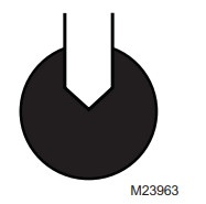

Fig. 1. Installation of SD-IS-525
Pre-Balancing:
Each valve has a built-in plug, which will permit pre-balancing the zone. To balance, remove the PowerTrack operator and locate the plastic plug on top of the valve. To turn the plug, engage a screwdriver in the slot on top of the plug. Turn the plastic plug clockwise until it bottoms out (2 to 3 turns), then back off counterclockwise until the desired flow rate is established. The table below gives approximate flow rates. It is based on commonly used residential circulators and piping practices. For other conditions, different settings may apply. (See INSTALLATION for removing and replacing operator).
| Turns from fully closed | ¼ | ½ | 1 | 1 ½ | 2 |
| The flow rate in GPM, ½ in. & ¾ in. valve | 1 ½ | 3 | 4 ½ | 6 | 7 ½ |
| The flow rate in GPM, 1.0 in. & 1 ¼ in. valve | 2 | 4 | 6 | 8 | 10 |
Manual Opening of Zone Valve:
To open, hold the PowerTrack operator with one hand and loosen the knurled brass nut 1 to 1 ½ turns counterclockwise. This opens the alve. To close the valve, follow instructions for installation steps 1, 2, and 3.
Replacement of PowerTrack Operator:
SHUT OF POWER. To remove and replace the PowerTrack operator, refer to section INSTALLATION. Replacement part numbers are: PowerTrack operator with switch MZV520, without switch MZV521.
Replacement of Valve Cartridge:
SHUT OF POWER and DRAIN SYSTEM, then follow instructions in section INSTALLATION. Part numbers are Cartridge for ½ in. and ¾ in. valve MZV525 RP, cartridge for 1 in. and 1 ¼ in. valve: MZV526 RP

Fig. 2. Wiring Diagram (No Switch or Switch not used)
SZ SERIES POWERTRACK™ MOTORIZED ZONE VALVE

Fig. 3. 2 Wire Wiring (No Switch or Switch not used).

NOTE: USE THIS CONNECTION DIAGRAM WHEN REPLACING THREE WIRE VALVES WITH FOUR WIRE PowerTrack™ VALVES.

Fig. 1. Installation of SD-IS-525
PowerTrack™ is a trademark of PosData, Inc.

Fig. 5. 4 Wire Wiring from SD-IS-525
TROUBLESHOOTING
Troubleshooting Guide
- If valve does not open when thermostat closes:
• Check voltage between yellow wires. Should be 22 to 28 volts. - Boiler and/or circulator continues to run after the valve has closed:
• Turn brass nut counterclockwise ¼ turn. - Valve leaks across seal:
• Make sure maximum allowable shut off pressure has not been exceeded.
• If allowable shut off pressure have not been exceeded, turn brass nut ¼ turn clockwise. - Valve chatters when closing:
• Check for proper flow direction.

62-3100—01

Automation and Control Solutions
Honeywell International Inc.
1985 Douglas Drive North
Golden Valley, MN 55422
customer.honeywell.com
® U.S. Registered Trademark
© 2007 Honeywell International Inc.
62-3100—01 J.I. 06-07
Honeywell Limited-Honeywell Limitée
35 Dynamic Drive
Toronto, Ontario M1V 4Z9