Honeywell HE360A B Powered Flow Through Humidifier Installation Guide


Template (entire sheet). Top of Humidifier
HE360A,B
Powered Flow-Through Humidifier
This is a legacy product document supported by Resideo. It is no longer manufactured
INSTALLATION INSTRUCTIONS
USE THIS TEMPLATE WHEN INSTALLING THE HE360 HUMIDIFIER SEE 69-1176EF OWNER’S GUIDE READ AND SAVE THESE INSTRUCTIONS
APPLICATION
The HE360A,B Powered Flow-Through Humidifier works with the warm air furnace blower to provide humidification for the whole house.
INSTALLATION
When Installing this Product…
- Read these instructions carefully. Failure to follow them could damage the product or cause a hazardous condition.
- Check the ratings given in the instructions and on the product to make sure the product is suitable for your application.
- Installer must be a trained, experienced service technician.
- After installation is complete, check out product operation as provided in these instructions.
CAUTION
Personal Injury or Equipment Hazard.
Improper drilling can cause equipment damage or personal injury.
- Do not cut or drill into any air conditioning or electrical accessory.
CAUTION
Property or Equipment Hazard.
Can cause property or equipment damage.
- Locate the humidifier where the ambient temperature is between 32°F (0°C) and 160°F (71°C) or property damage can occur.
- Do not install a humidifier where freezing temperatures could occur.
- Be sure supply plenum static pressure is no greater than 0.4 in. WC and water pressure is no greater than 125 psi.
IMPORTANT
- Mount the humidifier at least 3 in. (76 mm) above the furnace jacket to allow adequate space for the drain line. Check that there is adequate space above the humidifier to remove and install the humidifier cover. Do not install on a furnace jacket.
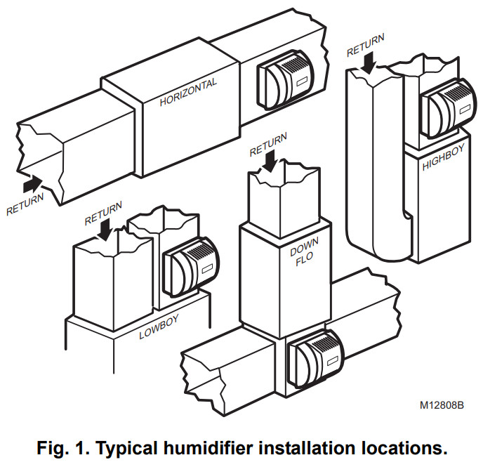
1. Determine the best location for the humidifier and draw a level line on the plenum. See Fig. 1 and 2.


IMPORTANT
To assure optimal product performance, be sure the template is level before marking.
- Tape the template in position and trace around the template.
- Remove the template and carefully cut the rectangular opening.
- Loosen the thumbscrew on the bottom of the humidifier and remove the cover.
- Remove the humidifier pad assembly by grasping the top of the tray and pulling the assembly out of the housing. See Fig. 3.
- Position the securing clips as shown in Fig. 4.
- Position the humidifier housing in the hole (be sure it is level), so the locking tabs are in place on the upper and lower sheet metal edge of the hole.
- Push in securing clips until completely seated.
- Drill holes and install the three sheet metal screws at the top of the humidifier housing. Secure the housing with the three remaining screws.
- Reinstall the humidifier pad assembly in the humidifier housing.
IMPORTANT
For proper operation, be sure the mark on the end of the humidifier pad is facing up. Check that the water feed tube is placed in the guide slots of the humidifier housing. - Hook the top of the cover to the housing and secure it with the thumbscrew located at the bottom of the cover.


WIRING
WARNING
Serious Personal Injury or Equipment Hazard.
Moving parts can cause electrical shock and injury.
- Disconnect power supply before installation or servicing.
- This device contains a moving fan blade; do not operate the humidifier without the cover securely attached.
All wiring must comply with applicable local codes, ordinances and regulations.
H8908 Humidistat Wiring Connections
IMPORTANT
- Select models of fan centers include humidifier taps so the current sensing relay or sail switch is not needed.
- If not using a current sensing relay or sail switch, the 120V humidifier plug must be energized during blower motorcycles for proper operation.
1. Wire the current sensing relay or sail switch.
2. Connect only the two yellow wires to the humidistat (red wire connections are not used for mechanical humidistats). See the typical wiring diagrams in Fig. 5 through 7.
For additional mounting and wiring information, refer to the humidistat installation instructions.

HE360A,B POWERED FLOW-THROUGH HUMIDIFIER

M12686A
Fig. 5. Typical wiring diagram for humidifier using fan control to
cycle blower motor fan and humidifier simultaneously.
- POWER SUPPLY. PROVIDE DISCONNECT MEANS AND OVERLOAD PROTECTION AS REQUIRED.
- 24V WIRING.


Fig. 7. Typical wiring diagram of sail switch with a humidifier.
Plumbing Saddle Valve
Hot or cold water, either hard or softened, can be used in the humidifier.
- Use the self-piercing saddle valve (included) to tap into the water supply line at an appropriate location.
CAUTION
Equipment Hazard.
Can cause equipment damage.
• Do not use any line connected to an air conditioner.
IMPORTANT
• The saddle valve is not designed to regulate water flow; the valve is either open or closed.
• To prevent debris from clogging the solenoid in-line filter, be sure to install the saddle valve handle pointing toward the ceiling.
NOTE: Lightly clean the copper tubing ends with fine sandpaper before making any connections. - Use 1/4 in. O.D. copper tubing and connect the saddle valve to the inlet side of the solenoid valve.
a. Place the brass compression nut over the copper tubing.
b. Slide the brass ferrule over the tubing.
NOTE: Do not over-tighten the compression nut. Moderate tightness prevents leaking.
c. Insert the tubing into the solenoid valve fitting and support the valve while tightening the compression nut.
NOTE: Slope hose downward for correct drainage. - Connect a 1/2 in. hose to the humidifier drain fitting and run it to a suitable drain.
CHECKOUT
- Open the saddle valve.
NOTE: The furnace blower must be operating for the humidifier to work. - Set the thermostat setpoint 10°F (6°C) above the room temperature.
- Set the humidistat to a high humidity setting, or place the humidistat in the test position.
- Observe the water running out of the drain line to be sure the a humidifier is working correctly.
- Check for leaks.
- Reset the thermostat and humidistat to comfortable settings.

Automation and Control Solutions
Honeywell International Inc.
1985 Douglas Drive North
Golden Valley, MN 55422
Honeywell Limited-Honeywell Limitée
35 Dynamic Drive
Toronto, Ontario M1V 4Z9
customer.honeywell.com
® U.S. Registered Trademark
© 2010 Honeywell International Inc.
69-1175EF—05 K.K. Rev. 02-10
Printed in U.S.A
Template (entire sheet)