Honeywell Q335 Dropout Thermocouple Installation Guide

Q335 Quick Dropout Thermocouple
This is a legacy product document supported by Resideo. It is no longer manufactured

INSTALLATION INSTRUCTIONS
APPLICATION
The Q335 Quick Dropout Thermocouple replaces the original thermocouple used to hold in the power unit of the VS8520 Millivolt Gas Valve. It installs in the Q382 Pilot Burner and can be replaced without removing the pilot burner or the associated thermopile. See Fig. 1.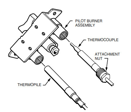
Hot Junction: 1400 F [760 C]. Cold Junction: 780 F [416 C].

INSTALLATION
WHEN INSTALLING THIS PRODUCT…
- Read these instructions carefully. Failure to follow them could damage the product or cause a hazardous condition.
- Check the ratings and descriptions given in the instructions to make sure the product is suitable for your application.
- The installer must be a trained, experienced service technician.
- After installation is complete, check out product operation as provided in these instructions.

Fire or Explosion Hazard. Can cause property damage, severe injury, or death.
Turn off the gas supply at appliance service valve before the beginning installation procedure to avoid dangerous accumulation of fuel gas.

Remove Old Thermocouple
- Hold the pilot burner assembly with one hand. On the other hand, loosen and remove the nut holding the thermocouple in the pilot burner. (Be careful not to damage or reposition the pilot burner.) See Fig. 1.
- . When the nut has been removed, pull the old thermocouple down and out of the pilot burner.
- Remove the nut at the other end of the thermopile that connects it to the power unit of the VS8520. Then emove the thermocouple lead from the VS8520.
- Discard the old thermocouple.
®U.S. Registered Trademark Copyright © 1998 Honeywell Inc. •


Install New Thermocouple
- Hold the pilot burner assembly with one hand. On the other hand, insert the new thermocouple in the pilot burner, pushing the thermocouple into the pilot burner until it stops. See Fig. 1.
- Engage attachment nut threads and firmly tighten the nut.
- Connect the female end of the thermocouple leads to the power unit of the VS8520.
- Engage the attachment nut threads and, using a wrench, tighten 1/4 turn beyond finger tight.
Important:
This is an electrical connection. Make sure that all connections are clean and tight for proper operation.
STARTUP AND CHECKOUT
Pilot Gas and Lighting Procedure
- Turn on gas supply to appliance. Leave thermostat set below room
temperature. - Relight appliance following the appliance manufacturerÕs instructions. If the manufacturerÕs instructions are not available proceed as follows to light the pilot.
NOTE: The pilot burner on some appliances is lit by a piezo-electric current (the pilot burner has an electrode as shown in Fig.1). If your appliance has an electrode for lighting the pilot burner, follow the appliance manufacturerÕs instructions. Do not use the instructions provided below.
- Turn the VS8520 gas control knob counterclockwise to the PILOT position, then push the knob down and hold it in position.
- While holding the knob down, light the pilot burner. Continue to hold down the knob until a strong flame is present (approximately 60 seconds).
- Release the knob; the pilot should continue to burn.
- Turn the gas control knob counterclockwise to the ON position.
- Turn up the thermostat to call for heat. The main gas valve should open and the main burner should ignite.
Adjust Pilot Flame
The pilot flame should envelop 3/8 to 1/2 in. (10 to 13 mm) of the tips of both the thermocouple and the thermopile. Refer to Fig. 2. If necessary, adjust the pilot flame as follows:
- Remove the pilot adjustment cover screw.
- Turn the inner pilot adjustment screw clockwise to decrease or counterclockwise to increase the pilot flame.
- Replace the pilot adjustment screw cover.

Fig. 2. The tip of the thermocouple must be in the pilot flame.
Check Safety Shutdown Performance
- Turn the thermostat below room temperature. The main burner should go out.
- Extinguish the pilot flame. Make sure that pilot gas flow stops within 30 seconds.
- Relight pilot burner by following the manufacturerÕs instructions.
Honeywell Inc.
Honeywell Plaza
P.O. Box 524
Minneapolis, MN 55408-0524

Home and Building Control
Honeywell Limited-Honeywell Limitée
155 Gordon Baker Road
North York, Ontario
M2H 3N7
paper containing at least 10% post-consumer paper fibers. 2
