Honeywell Service Kit for VU-Series Fan Coil Valves User Guide
Honeywell Service Kit for VU-Series Fan Coil Valves User Guide

APPLICATIONS
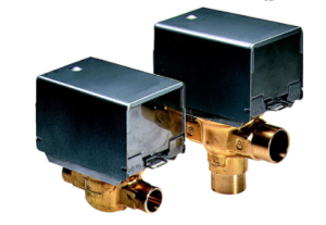
These service kits will convert VU52, VU53, and VU54 fan coil valves and their associated actuators to a Double-D stainless steel valve stem and brass sector gear for superior service life in closed hydronic systems using hot or chilled water with up to 60% glycol concentration. These valves are humidity resistant and are suitable for use in condensing, non-corrosive environments.
IMPORTANT
These valves are not for use in systems containing dissolved oxygen
SPECIFICATIONS
The specifications following are nominal and conform to generally accepted industry standards. Honeywell is not responsible for damages resulting from misapplication or misuse of its products.
Models
| QVU8142A | VU52, 2-way Normally Open | VU844A |
| QVU8143A | VU53, 2-way Normally Closed | VU843A |
| QVU8144A | VU54, 3-way mixing | VU844A |
Power Supply:
24 Vac, 50/60 Hz, 8 VA (0.32 A)
Approvals:
CSA C/US Certified.
Maximum Temperature Rating:
Standard models (with class A motor):
- 104°F(40°C) ambient @ 200°F(94°C) fluid.
Minimum Ambient Temperature:
34°F(1°C)
Shipping and Storage Temperature:
-40°C to 65°C (-40°F to 150°F).
Atmosphere:
Non-corrosive, non explosive, condensing.
Noise Rating:
Low Noise – non obtrusive
Materials:
Case, valves stem: stainless steel. Cover: aluminum. Sector gear: stamped brass Motor pinion: bronze Motor casing: zinc-plated steel
Body and stem O-rings: EPDM rubber Ball plug: Buna-N rubber Valve top: forged brass.
Max. Operating Pressure Rating:
300 psig (2000 kPa), 5X safety margin.
Close-off Pressure Rating:
See Figure 1.
INSTALLATION
When Installing this Product…
- Read these instructions carefully. Failure to follow them could damage the product or cause a hazardous
- Check the ratings given in the instructions and on the product to make sure the product is suitable for your
- Installer must be a trained, experienced service
- Make sure that the flow through the valve is in the direction indicated by the arrow stamped on the valve If not, valve body must be replaced or re- installed.
- After installation is complete, check out product operation as provided in these instructions.
WARNING
- Isolate valve with installed shut-off valves or flash- freeze service tool before removing spring clip that holds the actuator mounting plate to the valve body to prevent rapid decompression of
2. If shut-off valves or service tool are unavailable, drain system before servicing the valve.
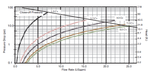

Figure 1. Flow and Close-off pressure ratings.
CAUTION
- Disconnect power supply before connecting wiring to prevent electrical shock or equipment damage.
- On 24V systems, never jumper the valve coil terminals even temporarily. This can burn out the heat anticipator in the thermostat.
- Wear safety glasses to protect eyes from injury when removing or installing the large spring clip that holds the actuator mounting plate to the valve body.
- Use proper snap ring pliers to remove or install spring clip.

Figure 2. VU actuator removal
Remove Existing Actuator
- Place manual operating lever on the actuator in the OPEN position. See Fig.2.
- Depress manual release loop and lift actuator off valve body
- Disconnect
Remove And Replace Actuator Mounting Plate From Valve Body
- Ensure valve is isolated or system drained before proceeding to disassemble valve body.
- Use drip pan under valve body to prevent property damage from water inside valve.
- Refer to exploded assembly view, Fig.3. Using snap ring pliers, squeeze and remove C-clip snap ring on top of valve.
- Lift actuator mounting plate off top of valve Note orientation of alignment tab.
- Remove body O-ring from inside valve. Inspect inside of valve for damage, remove debris, etc. as required.
- Place new body O-ring inside top lip of valve.
- Place new actuator mounting plate into top of valve, and align tab with slot. See Fig.4 for alignment of top on 2- way valves.
- Place C-clip in top of You may need to hold it in place.
- While holding C-clip into valve body top with one hand, use snap ring pliers to close C-clip until it snaps into the undercut groove around the inside top of the valve. Slight pressure may be needed on the actuator plate to compress body O-ring.
- IMPORTANT : Use feeler gauge provided to measure between tongues of C-clip snap ring to ensure actuator mounting plate is properly secured. The feeler gauge will pass freely between the ends of the snap ring only when the C-clip is seated fully in its groove. Failure to properly seat the C-clip can cause rapid decompression of the valve when it is re-pressurized resulting in
Install new Actuator
- Connect wiring. Use wire nuts or quick connect wiring plug, if Alternate quick connection plugs are provided with the unit and may be connected to the motor inside the actuator case using twist-on or crimp connectors (not provided).
- Using adjustable wrench, rotate valve stem so that flat sides of shaft are at right angles to the piping.
- Place manual operating lever on the actuator in the OPEN position.
- Snap actuator onto valve When properly seated, actuator will be in full contact with “castellated” valve rim. No additional attachment aids, such as tie-wraps
will be needed to hold the actuator securely to the valve. If this is not the case, remove and remount the actuator. - Optional: Release manual (If omitted, lever will reset to AUTO position on first automatic operation of valve.)

On Normally OPEN (NO) VU52 valves, shaft hub “S” is on side of body with alignment bump “B

On Normally CLOSED (NC) VU53 valves, shaft hub “S” is opposite side of body
Figure 4. Alignment of NO and NC 2-way valve tops

Figure 5. Proper feeler guage fit

Figure 6. C-clip alignment
OPERATION
CAUTION
On 24 V systems, never jumper the valve Coil terminals even temporarily. This can burn out the heat anticipator in the thermostat
Automatic Operation
On a call for heat or cool by the fan coil thermostat, the valve motor rotates the shaft or open (or close) the A port, depending on model. When the call ends, the valve closes by integral spring return. In
way valves, the B port is closed when the A port is open, and vice versa. 3-way valves may be installed for N.O. or N.C. operation by reversing connection of the A and B ports
Manual Operation
The 2-way normally closed and 3-way motorized valve actuators can be opened manually by lifting the manual opening lever over the stop and pushing slowly and firmly to the MAN. OPEN position. The stop permits the valve to be locked in the open position. The valve returns to automatic position when it is energized.
Normally Closed Models
With the manual opener set to AUTO and the actuator energized, the A port is open and water will flow in the coil. When the actuator is de-energized, a spring-return mechanism drives the valve to close the A port. The valve can also be opened with no electrical power by moving the manual opening lever over the stop and pushing slowly and firmly to the MAN.OPEN position. The stop permits the valve to be locked in an open position. The valve returns to the automatic position when cycled electrically.
Normally Open Models
With the manual opener set to AUTO and the actuator de-energized, the A port is open and water will flow in the coil. When the actuator is energized, the motor drives the valve to close the A port. When the motor is de-energized, a small spring puts the valve stem in motion, assisted by the force of the water.
Three Way Models
Three way valve bodies will operate as Normally Closed valves when the B port is connected to the coil bypass. The valve action is reversed when the A + B port connections are switched
CHECKOUT
Set to heating mode
Raise the setpoint on the zone thermostat above the room temperature to initiate a call for heat. Observe all control devices— the valve should open. Lower the setpoint on the zone thermostat below the room temperature. Observe the control devices. The valve should close.
Set to cooling mode
- Lower the setpoint on the zone thermostat below the room temperature to initiate a call for cooling.
- Observe all control devices—the valve should open.
- Raise the setpoint on the zone thermostat above the room temperature. Observe the control devices. The valve should close
By using this Honeywell literature, you agree that Honeywell will have no liability for any damages arising out of your use or modification to, the literature. You will defend and indemnify Honeywell, its affiliates and subsidiaries, from and against any liability, cost, or damages, including attorneys’ fees, arising out of, or resulting from, any modification to the literature by you.