Honeywell Braukmann F76 Water Filter Instruction Manual
Honeywell Braukmann F76 Water Filter Instruction Manual

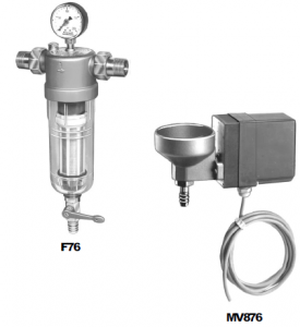
F76 Water Filters
and MV876 Automatic-Backwash Control Accessory (not included)

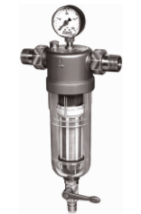
The F76 is a high flow capacity water filter used to remove sediment and debris from residential or commercial water systems. Used as a prefilter, the F76 protects elements of the water system, includ- ing specialized treatment devices or other common fixtures and appliances. The flow, filtering capac- ity, and ease of cleaning make the F76 the ideal filter for the most demanding applications.
The F76 uses a built-in backwash impeller for efficient cleaning with supply pressures as low as 21 psi. No shut-off or disassembly is required for cleaning and the design of the internal bypass eliminates the possibility of contamination from stagnant water. During backwashing, the F76 con- tinues to supply filtered water without interruption
through a secondary screen. Models are available for high temperature and high pressure applica- tions.
The MV876 Automatic-Backwash Controls are available as an accessory; order separately.
Specifications
MODELS:
F76A Standard Water Filter.
F76G High Pressure and Temperature Water Filter.
MATERIALS OF CONSTRUCTION:
Body: Brass Sump:
F76A: Engineered plastic F76G: Bronze
Screen: Stainless steel
Internal Construction: Acetal copolymer Seals: NBR
Ball Valve: Stainless steel with PTFE seals INLET PRESSURE:
Maximum: F76A: 230 psi
F76G: 400 psi
Minimum: 21 psi (with unrestricted backwash discharge) DIFFERENTIAL (MAXIMUM RECOMMENDED): 42 psi
OPERATING PRESSURE DROP (MAXIMUM RECOM-
MENDED): 3 psi (with clean screen) TEMPERATURE (MAXIMUM):
76A: 104°F(40°C) F76G: 180°F (82° C) PIPE SIZES AVAILBLE: 1/2, 3/4, 1, 1-1/4, 1-1/2, or 2 inches.
SCREEN SIZES:
F76A, F76G: 100 microns—20, 50, 100 and 200 micron screen kits available
NOTE: 20 microns = 900 mesh (approximate) 50 microns = 350 mesh (approximate)
100 microns = 175 mesh (approximate)
200 microns = 70 mesh (approximate)
CONNECTIONS:
Union on Inlet and Outlet: NPT threaded or sweat
Size the F76 based on the required flow rate and the resulting pressure drop across the filter. As a guideline for most applications, size the F76 to avoid pressure drops exceeding 3 psi.
EXAMPLE: To determine the size F76 required to provide a flow rate of 30 gpm, read across the chart (on the next page); at a pressure drop of 3 psi, 31.3 gpm can be provided by a 1-1/4 in. filter without exceeding the 3 psi pressure drop.
An increased pressure drop across the filter results when higher velocities are maintained to increase the capacity through any given size filter. Severe pressure drops occur when capacity approaches the pipe size.
Capacity in gallons per minute (gpm):
|
Pressure Drop (psi) |
Pipe Size | |||||
| 1/2 inch | 3/4 inch | 1
inch |
1-1/4
inch |
1-1/2
inch |
2
inch | |
| 1 | 6.5 | 6.5 | 16.7 | 18.5 | 26.0 | 30.0 |
| 2 | 9.2 | 9.2 | 24.0 | 25.8 | 36.5 | 42.5 |
| 3 | 11.4 | 11.4 | 29.1 | 31.3 | 44.9 | 52.0 |
| 4 | 13.2 | 13.2 | 33.9 | 36.9 | 52.4 | 60.3 |
| 5 | 14.5 | 14.5 | 37.4 | 40.7 | 57.2 | 66.0 |
| 15 | 22.0 | 22.0 | 65.0 | 70.0 | 95.0 | 115.0 |
NOTE: Cv is equal to capacity at 1 psi pressure drop.
DIMENSIONS: Refer to Fig. 1.
Fig. 1—F76 installation dimensions.

| Size |
L 1 |
l 1 |
D 1 |
H 1 |
h 1 |
Weight 2 | |
| Plastic | Bronze | ||||||
| 1/2 inch | 6.7 (170) | 4.3 (109) | 3.4 (86) | 14.5 (368) | 10.5 (267) | 2.6 (1.2) | 3.6 (1.6) |
| 3/4 inch | 7.0 (178) | 4.3 (109) | 3.4 (86) | 14.5 (368) | 10.5 (267) | 2.6 (1.2) | 3.6 (1.6) |
| 1 inch | 8.2 (208) | 5.1 (130) | 3.8 (97) | 16.7 (424) | 12.6 (320) | 4.6 (2.1) | 8.0 (3.6) |
| 1-1/4 inch | 8.7 (221) | 5.1 (130) | 3.8 (97) | 16.7 (424) | 12.6 (320) | 4.6 (2.1) | 8.0 (3.6) |
| 1-1/2 inch | 9.7 (246) | 5.9 (150) | 4.7 (119) | 20.8 (528) | 16.5 (419) | 8.8 (4.0) | 14.0 (6.4) |
| 2 Iinch | 10.5 (267) | 5.9 (150) | 4.7 (119) | 20.8 (528) | 16.5 (419) | 8.8 (4.0) | 14.0 (6.4) |


MV876 SPECIFICATIONS:
MV876Automatic-BackwashControls
Valve with 24 Vac motor and timer replaces ball valve drain port for automatic backwashing at preprogrammed intervals. Intervals are one backwash cycle every day or one backwash cycle every eight days. If more frequent backwashing is required, use an electromechanical timer (S4006B1008, ordered separately). 24V transformer is not included.
POWER: 4 VA
CURRENT: 170 mA
VOLTAGE: 24 Vac
CYCLE TIME: 20 seconds (approximate)
TIMER: Variable. One cycle per day or one cycle per eight days.
Planning the Installation
To ensure the backwash cycle operates properly and cleaning action is not reduced, follow all recommendations in Fig. 2. Refer to Fig. 2a for an ideal installation.
All filter installations are different. The size, type, and amount of dirt and debris and the flow rate must always be considered when choosing a screen and deciding to install F76 in parallel.
COMMERCIAL AND INDUSTRIAL INSTALLATIONS
Commercial and industrial installations have high flow requirements. For proper operation, limit the flow across the F76 screen. For example, a 2 inch pipe may have a flow of 120 gallons per minute at 12 feet per second linear velocity across a clean screen. This high linear velocity
impacts dirt very deeply into the screen, making it difficult to backwash and causing the screen to plug up very quickly. In these situations, install multiple F76 in parallel. Refer to Fig. 3.
When installing three F76 in parallel, a restriction must be installed in the outlet of the center F76 to maintain even flow through all three F76. Refer to Fig. 3.
Advantages of installing F76 in parallel:
- The cleaning capacity is Screens will not require backwashing as often.
- One F76 can be backwashed while the others maintain required downstream
Another consideration in commercial and industrial in- stallations is the backwashing frequency. Because of the high flow requirements, screens need cleaning on a regular basis. An MV876 Automatic-Backwash Control can be installed to backwash the F76 automatically either once every day or once every eight days. An optional S4006B1008 Electromechanical Timer can be installed with the MV876 to automatically backwash the F76 as often as once every hour.
Fig. 2—Installation recommendations
2a. Ideal F76 installation. A funnel mounted directly under the backwash port is the best installation layout.

2b. Ensure the inlet pipe is not downsized. Do not use 1/4 or 3/8 inch tubing on 1/2 or 3/4 inch models.

2c. Ensure the backwash outlet pipe is not downsized, long, or crimped. Instead, install a short oversized pipe on the backwash outlet. Do not use
a low capacity solenoid valve to automate the backwash cycle.

2d. Ensure the backwash outlet is not raised above the F76. If the backwash outlet must be raised above the F76, increase inlet pressure 5 psi forevery 10 feet it is raised.

2e. Ensure the F76 is not used with an undersize pump. An undersized pump may not provide proper pressure or flow.

2f. Ensure the F76 is not installed in a bypass across a pump.


Fig. 3—Installing three F76 in parallel.

Installation
INSTALLTHEF76(RefertoFig.4)
- Shut off the water supply by closing the water supply
- Install the F76 in the water line with the arrow pointing in the direction of water
- For F76A models, ensure the water temperature does not exceed 104o F and the water pressure does not exceed 230
- Before sweating, separate the tailpieces and nuts from the filter Excessive heating may damage the F76 internal parts.
- Install the pressure gauge in center port of the
- Install the backwash outlet handle on the F76 back- wash Installation screw is provided in place on the backwash outlet. If installing an MV876, follow the instruc- tions provided below.
- Install the backwash For best installation, refer to Fig. 2a.
- Close the backwash With the F76 air vent open, slowly open the water supply valve. When the F76 sump is full of water, close the air vent and fully open the supply valve.
SETTHEF76PRESSUREGAUGENEEDLES
The black needle on the pressure gauge measures the F76 outlet pressure. When the F76 is running with clean screens, there is no pressure drop across the F76 (outlet pressure equals the inlet pressure).
The red needle is a stationary needle that helps monitor backwashing frequency.
- Backwash the F76 once to ensure the screens are
- With the F76 in operation, use a screwdriver to set the red needle to the same position as the black
As the F76 operates, the screens become plugged. As a general rule, the F76 should be backwashed when the black needle measures about 5 psi lower than the red needle. However, each installation is different. In residential appli- cations, the F76 may need backwashing once every few weeks or months. In industrial applications, the F76 may need backwashing several times a day.
INSTALLTHEMV876
- If the MV876 is being added to an existing F76, shut off the water supply by closing the water supply Drain all water from the F76 by opening a fixture downstream, opening the backwash outlet, and loosening the air vent on top of the F76.
- Remove the backwash outlet from the F76 sump by turning the outlet counterclockwise (as viewed from the bottom looking up).
- Install the backwash outlet included with the Ensure the plastic washer (two washers for MV876A1022) is placed between the filter sump and the backwash outlet.When the correct number of washers are not installed, the backwash outlet and the MV876 will not align properly.
- Close the backwash outlet on the MV876 with a
- Fit the MV876 brass housing onto the Align the backwash stem with the opening in the housing.
- Insert the actuator bushing into the housing Turn until finger tight. Ensure the bushing is in the correct position over the backwash stem as shown in Fig. 5.
- Push the driver insert adapter into the bushing as The driver head of the insert must engage the slot in the backwash stem. The correct position of the components is shown in Fig. 6.
- Tighten the actuator
Fig. 4—Installing the F76.
- Fit the timer actuator shaft into the driver insert. Ensure the pins in the shaft engage the slots in the driver Fasten the actuator to the brass housing using the screws provid
- Mount the AT140A1034 Transformer and wire as shown in Fig. 7.
- With the F76 air vent open, slowly open the water supply valve. When the F76 sump is full of water, close the air vent and fully open the supply valve.
- Reconnect power to the system. When the system is powered, the MV876 runs through one backwash cycle (approximately 20 seconds).
- Set the backwash frequency for the MV876 to the desired setting (one backwash every day or one backwash every eight days). If a greater backwash frequency is required, install an S4006B1008 Electromechanical Timer. Follow the instructions provided below.
- Check the operation of the MV876 by interrupting primary power to the transformer. When power is switchedback on, the MV876 backwashes the F76 once.

Fig. 5—Installing the MV876.

Fig. 6—Final position of MV876 and F76 components.

Fig. 7—Wiring diagram for F76 with MV876.

INSTALLINGTHEMV876WITHS4006B1008 ELECTROMECHANICAL TIMER
CAUTION
- Disconnect power supply before wiring to prevent electrical shock or equipment dam-
- All wiring must comply with applicable codes and
- Install the MV876 and F76 using the instructions
- Wire the S4006B1008 Electromechanical Timer, AT140A1034 Transformer, and MV876 Automatic-Back-
- Set the timer to the correct time using the S4006B1008
- To backwash at a selected time, raise the appropriate tripper on the A raised tripper supplies power to the MV876 for one-half hour. The MV876 completes one back- wash cycle each time a tripper switches power on.
- Ensure the trippers adjacent to a raised tripper are in the down position to remove power at the end of 30
- To backwash once every hour (24 times every day), set the trippers alternately up and down around the This is the maximum number of times per day that the F76 can be backwashed using the S4006B1008 and MV876.
Fig. 8—Wiring diagram for F76 with MV876 and S4006B1008.

Replacement Parts
| Description | 1/2 inch | 3/4 inch | 1 inch | 1-1/4 inch | 1-1/2 inch | 2 inch |
| (A) Pressure Gauge Clear Plastic (F76A) Bronze (F76B) | 0901537 5267400 |
0901537 5267400 |
0901537 5267400 |
0901537 5267400 |
0901537 5267400 |
0901537 5267400 |
| (B) Tailpieces Sweat Threaded (shown) |
U76S5007 U76T1006 |
U76S5015 U76T1014 |
U76S5023 U76T1022 |
U76S5031 U76T1030 |
U76S5039 U76T1038 |
U76S5047 U76T1046 |
| (C) Union Nut | N/A | N/A | N/A | N/A | N/A | N/A |
| (D) Tailpiece Gasket | N/A | N/A | N/A | N/A | N/A | N/A |
| (E) Ring (Brass or Plastic) Screen Kit 20 Micron 50 Micron 100 Micron 200 Micron Includes: (F) Upper Screen (H) Barrel O-Ring (L) Lower Screen |
N/A
QF76Q2007 QF76R2030 QF76S2051 QF76T2074 |
N/A
QF76Q2007 QF76R2030 QF76S2051 QF76T2074 |
N/A
QF76Q2015 QF76R2038 QF76S2059 QF76T2082 |
N/A
QF76Q2015 QF76R2038 QF76S2059 QF76T2082 |
N/A
QF76Q2023 QF76R2046 QF76S2067 QF76T2090 |
N/A
QF76Q2023 QF76R2046 QF76S2067 QF76T2090 |
| Description | 1/2 inch | 3/4 inch | 1 inch | 1-1/4 inch | 1-1/2 inch | 2 inch |
| Internal Seal Kit Includes: (H) Barrel O-Ring (K) Screen Seal (Q) Chamber O-Ring (S) Joint Ring Seal |
N/A | N/A | N/A | N/A | N/A | N/A |
| Filter Insert Kit Includes: (F) Upper Screen (G) Upper Guide Barrel (H) Barrel O-Ring (J) Lower Guide Barrel (K) Screen Seal (L) Lower Screen (M) Impeller (N) Lower Screen Support (P) Conical Base Spring (Q) Chamber O-Ring |
QF76G2053 | QF76G2053 | QF76G2061 | QF76G2061 | QF76G2069 | QF76G2069 |
| Filter Sump Kit Clear Plastic Bronze Includes: (Q) Chamber O-Ring (R) Sump (S) Joint Ring Seal (T) Drain Tap (Backwash Outlet) (U) Red Handle and Screw |
PF76C1007 202913 |
PF76C1007 202913 |
PF76C1015 202914 |
PF76C1015 202914 |
PF76C1023 202915 |
PF76C1023 202915 |
| Drain Tap Assembly Includes: (S) Joint Ring Seal (T) Drain Tap (Backwash outlet) (U) Red Handle and Screw |
2341300 | 2341300 | 2341300 | 2341300 | 2341400 | 2341400 |
| (U) Red Handle and Screw | N/A | N/A | N/A | N/A | N/A | N/A |
| Sump Wrench | N/A | N/A | N/A | N/A | N/A | N/A |
N/A = Part number not available at time of printing.
a Models F76A and F76B are clear plastic.
b Models F76G and F76H are bronze.
Fig. 9—F76 Exploded View.
