Honeywell C554A Cadmium Sulfide Flame Detector Installation Guide


This is a legacy product document supported by Resideo. It is no longer manufactured
C554A Cadmium Sulfide Flame Detector
TRADELINE®
INSTALLATION INSTRUCTIONS
APPLICATION
The C554A Cadmium Sulfide Flame Detector (cad cell) is a photoconductive flame detector (see Fig. 1) used with oil primary controls such as R4166, R4184, R8182, R8184, R8185, R8404 and R8991. It consists of a plug-in, light sensitive cell and a socket with Type E mounting bracket, factory-installed leadwire and an oil line adapter bracket. Leadwire length is 60 in. (1520 mm). The detector is installed inside the air tube of the burner where the cell can view the flame and is wired to the F-F terminals of the oil primary control.
The photocell is a ceramic disk coated with cadmium sulfide and overlaid with a conductive grid. Electrodes attached to the ceramic disk transmit an electrical signal to the primary control. In darkness, cadmium sulfide has a very high resistance to the passage of electrical current. In visible light, its resistance is very low and current is allowed to pass. The entire cell is hermetically sealed (glass to metal) to prevent cell deterioration.
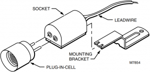

Fig. 1. C554A Cadmium Sulfide Flame Detector (cad cell).
INSTALLATION
When Installing this Product…
- Read these instructions carefully. Failure to follow them could damage the product or cause a hazardous condition.
- Check the ratings given in the instructions and on the product to make sure the product is suitable for your application.
- Installer must be a trained, experienced service technician.
- After installation is complete, check out product operation as provided in these instructions.

Disconnect power supply before beginning installation to prevent electrical shock or equipment damage.
Location
The burner manufacturer determines the the cad cell location (see Fig. 2). If an alternate location must be used, make sure that:
- The cell has a clear view of the flame.
- Ambient light does not reach the cell.
- Ambient temperature at the cell location is below 140°F (60°C).
- Movement, shielding, or radiation of metal surfaces loated near the cell do not affect cell operation.

Fig. 2. Cad cell location.
Mounting
Direct Replacement
1. Remove the cell from the socket.
2. Insert the mounting bracket into the socket slot (Fig. 3) as far as it will go.
NOTE: Bend the mounting bracket to fit, if necessary

®U.S. Registered Trademark
Copyright © 1996 Honeywell Inc. • All Rights Reserved
3. While holding the mounting bracket in the slot, insert the screwdriver in the other end of the slot (Fig. 4). Bend the screwdriver, first to the left and then to the right, to crimp the end of the mounting bracket and hold it in position.
4. Remove the screwdriver and replace the cell.
5. Mount the new cell and bracket assembly in the location of the old assembly.

Fig. 3. Insert mounting bracket into socket slot.
Oil Line Mounting
If desired, mount the C554A on the oil line using the oil line adapter bracket and the mounting bracket supplied.
1. Remove the cell from the socket.
2. Insert the mounting bracket into the slot on the socket (Fig. 3) as far as it will go.
NOTE: Bend the mounting bracket to fit, if necessary.
3. While holding the mounting bracket in the slot, insert the screwdriver in the other end of the slot (Fig. 4). Bend the screwdriver, first to the left and then to the right, to crimp the end of the mounting bracket and hold it in position.
4. Remove the screwdriver and replace the cell.
5. Slide the mounting bracket into the sleeve on the oil line adapter bracket. Push firmly to lock the cell and the bracket assembly in position.
6. Mount the oil line adapter bracket on the oil line using the screw and nut provided (Fig. 5).

INSERT SCREWDRIVER AND MOVE IN DIRECTION SHOWN BY ARROWS TO SECURE BRACKET IN SOCKET

Fig. 4. Insert screwdriver to secure bracket in socket.
2

Fig. 5. Use oil line adapter bracket to mount C554A on oil line.
Wiring
Disconnect power supply before beginning wiring to prevent electrical shock or equipment damage.
All wiring must comply with local electrical codes and ordinances. See Fig. 6 for a typical C554A hookup to the oil burner primary control.

Fig. 6. Typical hookup for C554A to oil burner primary control.
CHECKOUT
To check cad cell operation, use the following procedure:
1. Disconnect the cad cell leadwires; then start the burner. Shortly after the burner starts, place a temporary jumper between terminals F-F. Connect the ohmmeter across the cad cell leadwires; resistance should be less than 1600 ohms.
2. Stop the burner and remove the temporary jumper.
3. With the burner off, check the dark cell resistance across the cad cell leadwires. Resistance should be greater than 20,000 ohms.
NOTE: If cell resistances are different than specified, recheck the wiring and location of the cell. If necessary, replace the plug-in part of the cell, Honeywell part no. 130367 Replacement Cad Cell.
4. Reconnect the cad cell leadwires. Check the Protectorelay“ Burner Sequencing Relay control according to the instructions packed with the control.
SERVICE AND REPLACEMENT
Under normal operating conditions, the C554A does not require cleaning. If a badly adjusted burner causes heavy accumulation of dirt and soot on the cell surface, carefully wipe the cell surface to restore full view of the oil flame.
If the C554A is damaged, replace the plug-in part of the cell. Order Honeywell part no. 130367 Replacement Cad Cell.
3

Automation and Control Solutions
Honeywell International Inc. Honeywell Limited-Honeywell Limitée
1985 Douglas Drive North 35 Dynamic Drive
Golden Valley, MN 55422 Toronto, Ontario M1V 4Z9
60-0164B—1 J.S. 3-96
