Honeywell WSK-24 Wireless Occupancy Solution Installation Guide


This is a legacy product document supported by Resideo. It is no longer manufactured
WSK-24 Wireless Occupancy Solution
INSTALLATION INSTRUCTIONS

PRODUCT DESCRIPTION
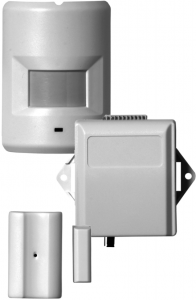
The WSK-24 Wireless Occupancy Solution automatically controls HVAC equipment by determining when a room is occupied. The WSK-24 uses the combination of an occupancy sensor and a door switch to provide optimal control. The WSK-24 is packaged in a kit that includes the following components:
- One 24V dry contact receiver
- One wireless PIR (passive infrared receiver) occupancy sensor with mounting kit
- One wireless door sensor with mounting kit
- One wiring harness.
The receiver can be wired into any thermostat or controller that supports the connection of a remote setback device. The receiver communicates wirelessly to a PIR occupancy sensor, a door sensor, and an optional 2nd door/window sensor. After the receiver determines that the room is unoccupied it closes a dry contact switch. After the thermostat or controller recognizes the contact closure, it places the thermostat in economy setback mode, which provides energy savings for when the room is unoccupied.
FEATURES
- Wireless system provides quick and easy installation
- Pre-configured door sensor and occupancy sensor
- Guest comfort is maintained by never turning off HVAC equipment when someone is in the room – even if they are sleeping
- Fuse protection
- Long battery life
- Low battery indication
- Receiver memory retained after power loss
- Optional sliding door/window sensor can be easily added
- Compatible with TB8575 fan coil thermostats
- Compatible with TB6575 fan coil thermostats, but requires separate 24 VAC transformer
- Compatible with T7350 / T7351 thermostats, but requires a separate relay to reverse relay logic
- Other thermostats might also require a separate relay; the WSK-24 closes the contact when occupied

ORDERING INFORMATION
When purchasing replacement and modernization products from your TRADELINE® wholesaler or distributor, refer to the TRADELINE® catalog or price sheets for complete ordering number. Orders can also be placed at http://customer.honeywell. com.
If you have additional questions, need further information, or would like to comment on our products or services, please write or phone:
- Your local Honeywell Automation and Control Products sales office (check the white pages of your phone directory).
- Honeywell Customer Care 1985 Douglas Drive North Minneapolis, Minnesota 55422-4386 (763) 954-5720
- In Canada–Honeywell Limited/Honeywell Limitée, 35 Dynamic Drive, Toronto, Ontario M1V 4Z9.
International sales and service offices are located in all principal cities of the world. Manufacturing is in Australia, Canada, Finland, France, Germany, Japan, Mexico, the Netherlands, Spain, Taiwan, United Kingdom, and U.S.A.
SPECIFICATIONS
Operating Temperature:
Receiver: -21 to 60°C (-5 to 140°F)
Door Sensora: -20 to 60°C (-4 to 140°F)
PIR Sensor: -20 to 40°C (-4 to 104°F)
Power Supply:
Receiver: 24 Vac/Vdc at 50/60 Hz; Standby power consumption 15 mA; Channel 1 relay output, N.O.
Door Sensora: Two CR2032 lithium batteries
PIR Sensor: Three AAA E92 1.5V alkaline batteries
Battery Life:
Door Sensora: Two years (under normal usage)
PIR Sensor: One year (under normal usage)
Receiver Operating Frequency:
Receiver: 433.92 MHz
Door Sensora: 433.92 MHz
PIR Sensor: 433.92 MHz
Receiver Frequency Range:
- With antenna exposed:
• Open Range: 200 ft.
• Typical Range: 100 ft. - With antenna coiled inside receiver:
• Open Range: 50 ft.
• Typical Range: 40 ft.
PIR Detection Pattern:
Length: 3 to 8 meters when mounted 2 meters above the floor (see Fig. 1)
Angle: 140 degrees (see Fig. 2)

Fig. 1. Side view of PIR detection pattern.
Fig. 2. Top view of PIR detection pattern.

Dimensions:
Door Sensora: 1.4 x 2.3 x 0.6 in (35.8 x 57.6 x 15.2 mm)
Receiver: 3.6 x 3.4 x 1.2 in (91.4 x 86.4 x 30.5 mm)
PIR Sensor: 2.8 x 3.9 x 1.1 in (71 x 100 x 28 mm)
Approvals: FCC Part 15 Class B
Accessories:
- 50037735-001: Optional Sliding Door/Window Sensor
Replacement Parts:
- 50037737-001: Wireless Receiver
- 50037736-001: Wireless PIR Occupancy Sensor
a and 50037735-001, the optional sliding door/window sensor
62-0300—01 2
INSTALLATION
When Installing this Product…
- Read these instructions carefully. Failure to follow them could damage the product or cause a hazardous condition.
- Check the ratings given in the instructions and on the product to make sure the product is suitable for your application.
- Installer must be a trained and experienced service technician.

Risk of electrical shock.
Can cause severe injury, property damage or death.
Disconnect power supply before installation and before servicing.
IMPORTANT
The thermostat may be a line voltage powered device. All wiring must comply with national and local electrical codes, ordinances and regulations.
The WSK-24 must be powered by an Approved 24 Vac, Class 2, NEMA rated transformer.
Thermostat Configuration
Refer to the thermostat’s installation instructions for programming, mounting, and wiring the thermostat.
The receiver has a normally open dry contact relay. Therefore, the thermostat should be set so that the relay on the thermostat is normally closed.
Use Table 1 or Table 2 to determine the desired Installer Codes for the thermostat being used with the WSK-24.
Table 1. MultiPRO™ Installer Setup Codes.
| IS Code | Code Description | Option Value | Option Description |
| 0160 | Schedule Options | 0 | Non-Programmable |
| 0340 (Nonprogram mable) | Remote Temp Sensor/Remote Setback/ Changeover Input | 5 | Remote Setback |
| 0341 | Delay for Remote Setback | 0 | No Delay |
| 2 | Two Minute Delay | ||
| 0342 | Override Option | 0 | No Override during unoccupied |
| 1 | Override during unoccupied | ||
| 0343 | Unoccupied Heating Setpoint | 50-65 | Range is 50 to 65°F (10 to 18°C) |
| 0346 | Unoccupied Cooling Setpoint | 75-90 | Range is 75 to 90°F (24 to 30°C) |
Table 2. SuitePRO™ Installer Setup (IS) Codes.
| IS Code | Code Description | Option Value | Option Description |
| 19 | Remote Setback | 2 | Hotel Card enabled N.C. with 1 second software delay going from UnOccupied to Occupied; 2 minute delay going from Occupied to UnOccupied. |
| 4 | Hotel Card enabled N.C. with 1 second software delay going from UnOccupied to Occupied; 30 minute delay going from Occupied to UnOccupied. | ||
| 20 | Remote Setback for Heating | 50-70 | Range is 50 to 70°F (10 to 21°C) |
| 21 | Remote Setback for Cooling | 72-90 | Range is 72 to 90°F (22 to 32°C) |
Wiring
Prepare Thermostat for Receiver Wiring
Turn off the thermostat and remove the power source from the thermostat.
Risk of electrical shock.
Can cause severe injury, property damage or death.
Disconnect power supply before servicing.

Equipment Damage Hazard.
Improper removal can damage the thermostat.
Carefully follow the thermostat removal directions.
Receiver and Thermostat Terminal Wiring
Table 3. Wiring Designations
| Receiver Harness Wire | Typical Thermostat Terminals | Connection |
| Red | R | 24 Vac Power |
| White | C | 24 Vac Common |
| White/ Brown | Sc | Dry Contact; Normally Open |
| Brown | Sb | Dry Contact; Common |
3

1. WIRE RED AND WHITE WIRES TO 24 VAC POWER AND COMMON.
2. WIRE WHITE/BROWN AND BROWN WIRES TO DRY CONTACT TERMINALS ON THERMOSTAT.
Fig. 3. Receiver and wiring harness.
Using Table 3 on page 3 and Fig. 3, wire the harness to the thermostat and connect the harness to the receiver.
- Wire the red and white power leads on the wiring harness into the power terminals on the thermostat.
- Wire the white/brown and brown dry contact leads on the wiring harness into the remote setback terminals on the thermostat.
- Plug the wiring harness into the receiver. The harness is keyed and fits only one way.
- Supply power to the thermostat.
- The LED on the receiver flashes twice to show it has power.
- Continue with “Setting the Delay on the Receiver”.
Wiring Diagram Example for a Switching Relay (R8222N1011/U*)

1 POWER SUPPLY. PROVIDE DISCONNECT MEANS AND OVERLOAD PROTECTION AS REQUIRED.
2 ENSURE TRANSFORMER IS SIZED TO HANDLE THE LOAD.
3 HEAT/COOL SYSTEMS WITH ONE TRANSFORMER REQUIRE THE FACTORY-INSTALLED JUMPER.
4 USE ECONOMIZER INSTRUCTIONS FOR INSTALLATION DIRECTIONS.
Fig. 4. Example of wiring diagram when using with T7350/T7351 thermostat.
* Either R8222B1067 (24VAC, SPDT) or R8222N1011 (24VAC, DPDT, Pilot duty) can be used for switching relay.
4
Setting the Delay on the Receiver
Refer to Fig. 5 and position the jumper to the desired delay option:
Position the jumper near the pushbutton:
— Front Door – 3 minute delay
— 2nd optional door – 1 minute delay
Position the jumper away from the pushbutton (default position):
— Front Door – 15 second delay
— 2nd optional door – 1 minute delay
The receiver delay and the delay that is programmed in the thermostat will be combined to provide an overall delay.
Mounting
Mounting the Receiver
The receiver can be mounted behind the thermostat in the wall, inside the fan coil unit, or mounted on the wall.
Mounting screws or double-sided adhesive tape can be used to mount the receiver.


Fig. 5. Receiver components.
Mounting the Door Sensor
1. Remove battery tab before installation. See Fig. 6.
Fig. 6. Battery tab removal.

2. Remove the plastic mounting bracket from the door sensor housing.
3. Place the mounting bracket for the door sensor high on the frame of the front door. Secure the bracket to the door frame by using the two screws or adhesive tape provided. See Fig. 7 on page 5.

4. Make sure the notched side of the door sensor is pointing in the direction that you will mount the magnet. See Fig. 8 and Fig. 9.


Fig. 8. Door sensor tab notches.
5. Snap the sensor in place.
6. Align one end of the magnet with the notched side of the door sensor housing.
7. Mount the magnet a maximum of 3/4 in. (19 mm) from the door sensor, as illustrated in Fig. 9.

1 MAXIMUM DISTANCE BETWEEN SENSOR AND MAGNET 3/4 (19).
Fig. 9. Maximum distance between door sensor and magnet.
5
8. Secure the magnet to the door by using the two screws or adhesive tape provided. An optional spacer is provided, as well. See Fig. 10.

Fig. 10. Door magnet mounting options.
9. Open and close the door to ensure that there is no interference.
CHECK THE DOOR SENSOR FUNCTION
- Open the door and verify that the LED on the door sensor flashes three times when the contact is opened.
- Close the door and verify that the LED on the door sensor flashes another three times.
Mounting the PIR Occupancy Motion Sensor

Fig. 11. PIR occupancy motion sensor mounting options.
- Take off the cover by removing the cover release screw on the bottom of the PIR back plate.
- Power the PIR sensor by inserting the three AAA batteries provided. See Fig. 13 for proper battery orientation.
- Secure the PIR sensor to the wall using one of the following three options
a. Wall Mount option 1: Use the adhesive tape to secure the PIR back plate to the wall.
b. Wall mount option 2: Using either the top or bottom two holes of the PIR back plate, insert the two long screws to secure the PIR back plate to the wall.
c. Ceiling mount option: Align the mounting bracket and PIR back plate as shown in Fig. 11. Insert the two small screws into the top holes of the back plate and secure it to the bracket. Use the two long screws (and, if necessary, the optional plastic anchors) and mount the bracket and PIR back plate to the ceiling. - Replace the PIR sensor cover and replace the cover release screw on the bottom of the sensor.
CHECK THE PIR OCCUPANCY MOTION SENSOR FUNCTION
- Create motion in front of the PIR sensor and verify that its LED flashes three times when motion is detected.
• The PIR sensor continues to flash while motion is detected. - Cover the PIR sensor and verify that its LED stops flashing.
- Uncover the PIR sensor.
Battery Replacement
For correct battery replacement, note the battery polarity orientations in Fig. 12 and Fig. 13.


Fig. 13. PIR occupancy sensor battery replacement.
6
Low-Battery Indication
When a low battery condition is detected in the door sensor or the PIR occupancy sensor, the LED status indicator on the device flashes for four (4) seconds.
OPERATION
Door (Zone 1) and PIR Occupancy Motion Sensor (Zone 2)
The door sensor and PIR occupancy motion sensor are packaged factory-configured to the receiver. There is no need for the receiver to discover these sensors. The door and PIR sensors wirelessly connect to the receiver right out of the box. Simply wire and mount the receiver and sensors and the system will work properly.
When the door is opened and then closed, a signal is sent to the PIR sensor to begin looking for motion. As soon as the PIR senses someone is in the room, the receiver clicks the relay to turn the thermostat back into the occupied setpoints. If the person does not leave the room, the thermostat will always stay in the occupied mode, regardless if the PIR sensor stops sensing motion. This provides a comfortable environment for guests and ensures that the HVAC equipment does not turn off while guests are sleeping.
When a guest opens and closes the door and leaves the room, the PIR sensor starts looking for motion again. If the PIR sensor does not sense motion, the receiver closes the relay after 15 seconds or 3 minutes (depending on how the jumper is positioned) and the thermostat goes into the unoccupied economy mode. The overall delay depends on the delay that is programmed in the thermostat.
The PIR sensor always overrides the unoccupied economy mode, as soon as it senses motion. For example, if there are two guests in the room and guest A is in the bathroom while guest B leaves the room, the thermostat goes into economy setback mode if no motion is detected. As soon as guest A leaves the bathroom and enters the main room, the PIR senses motion and returns the thermostat to normal operation. The thermostat continues in normal operation until someone opens and closes the front door and the PIR stops sensing motion.
Optional Sliding Door/Window Sensor (Zone 3)
Because the sliding door/window sensor is an optional accessory, the receiver needs to discover this new zone. After the sliding door/window sensor is powered, follow these steps to add the optional sliding door/window sensor. It is easiest to do this before the sensor is mounted.
NOTE: The sliding door/window sensor is identical to the door sensor supplied with the WSK-24 Wireless Occupancy Solution.
- Remove the battery tab from the sliding door/window sensor. See Fig. 6 on page 5.
- Make sure the sliding door/window sensor and magnet are close to each other, within 3/4 in. (19 mm), and that the tab notches on the sensor face the magnet. See Fig. 9 on page 5.
- At the receiver and press the black pushbutton three times for Zone 3 (see Fig. 5 on page 5). The red LED on the opposite side of the receiver will flash three times. See Fig. 5 on page 5 for location of the pushbutton and LED.
- Open and close Zone 3 by moving the magnet away from the sliding door/window sensor and bringing it back to contact. The red LED on the receiver will flash another 3 times to indicate that Zone 3 is discovered.
- Mount the sliding door/window sensor and magnet using the same mounting procedure as described in “Mounting the Door Sensor” on page 5.
After the sliding door or window is opened and left open for longer than 1 minute, the receiver closes the relay and the thermostat goes into the unoccupied economy mode. The overall delay depends on the delay that is programmed in the thermostat. The occupant cannot change the thermostat settings while the sliding door or window is open. As soon as the sliding door or window is closed, the thermostat returns to normal operation.
SENSOR DISCOVERY
NOTE: The WSK-24 Wireless Occupancy Solution comes with the front door sensor and the PIR occupancy motion sensor already discovered by the receiver. There should be no need to rediscover these devices. However, this information is provided for troubleshooting purposes.
Deleting all Sensors
- Press and hold the black pushbutton (see Fig. 5 on page 5) on the receiver for six (6) seconds.
- The red LED on the receiver flashes once to confirm that all sensors have been deleted.
Adding Zone 1 (Door Sensor)
- Make sure the PIR sensor is covered.
- Make sure the door contact is closed.
- Press the black pushbutton on the receiver one time. The red LED on the receiver flashes once.
- Now activate the door sensor by removing the magnet. The red LED on the receiver flashes once to confirm the device has been discovered.
- Uncover the PIR sensor.
Adding Zone 2 (PIR Occupancy Motion Sensor)
- Make sure the PIR sensor is covered.
- Press the black pushbutton on the receiver two times. The red LED on the receiver flashes twice.
- Now activate the PIR sensor by uncovering the sensor and moving in front of it. The red LED on the receiver flashes twice to confirm the device has been discovered.
Adding Zone 3 (Optional Sliding Door/ Window Sensor)
- Make sure the PIR sensor is covered.
- Make sure the sliding door/window contact is closed.
- Press the black pushbutton on the receiver three times. The red LED on the receiver flashes three times.
- Now activate the sliding door/window sensor by removing the magnet. The red LED on the receiver flashes three times to confirm the device has been discovered.
- Uncover the PIR sensor.
SYSTEM TESTING
Perform the following to test the sensors.
Front Door Sensor & PIR Sensor
- Position the jumper away from the pushbutton to set the minimal time delay (15 seconds).
- Cover the PIR sensor so it cannot sense motion.
- Open and close the front door sensor. The receiver closes its relay after 15 seconds, and you will hear the relay click on the receiver.
- Wait for the thermostat to go into unoccupied mode. The overall delay will depend on the additional time delay that is configured in the thermostat.
- Uncover the PIR sensor so that it can now sense motion.
- The receiver opens the relay and the thermostat returns to occupied mode immediately.
- Position the jumper back to the desired time delay. (See “Setting the Delay on the Receiver” on page 5.)
2nd Door Sensor
- Open the 2nd door sensor. The receiver closes its relay after 1 minute, and you will hear the relay click on the receiver.
- Wait for the thermostat to go into unoccupied mode. The overall delay depends on the additional time delay that is configured in the thermostat.
- Keep the door open and move in front of the PIR sensor so that it can sense motion. The thermostat should remain in the unoccupied mode.
- Close the 2nd door sensor. The receiver opens its relay and the thermostat returns to occupied mode immediately.
LIMITED TWO-YEAR WARRANTY
Honeywell warrants this product, excluding battery, to be free from defects in the workmanship or materials, under normal use and service, for a period of two (2) years from the date of purchase by the consumer. If, at any time during the warranty period, the product is defective or malfunctions, Honeywell shall repair or replace it (at Honeywell’s option) within a reasonable period of time.
If the product is defective,
(i) return it, with a bill of sale or other dated proof of purchase, to the retailer from which you purchased it, or
(ii) package it carefully, along with proof of purchase (including date of purchase) and a short description of the malfunction, and mail it, postage prepaid, to the following address:
Honeywell Return Goods
Dock 4 – MN10-3860
1985 Douglas Dr. N
Golden Valley, MN 55422
This warranty does not cover removal or reinstallation costs. This warranty shall not apply if it is shown by Honeywell that the defect or malfunction was caused by damage which occurred while the product was in the possession of a consumer.
Honeywell’s sole responsibility shall be to repair or replace the product within the terms stated above. HONEYWELL SHALL NOT BE LIABLE FOR ANY LOSS OR DAMAGE OF ANY KIND,INCLUDING ANY INCIDENTAL OR CONSEQUENTIAL DAMAGES RESULTING, DIRECTLY OR INDIRECTLY, FROM ANY BREACH OF ANY WARRANTY, EXPRESS OR IMPLIED, OR ANY OTHER FAILURE OF THIS PRODUCT. Some states do not allow the exclusion or limitation of incidental or consequential damages, so this limitation may not apply to you.
THIS WARRANTY IS THE ONLY EXPRESS WARRANTY HONEYWELL MAKES ON THIS PRODUCT. THE DURATION OF ANY IMPLIED WARRANTIES, INCLUDING THE WARRANTIES OF MERCHANTABILITY AND FITNESS FOR A PARTICULAR PURPOSE, IS HEREBY LIMITED TO THE TWO YEAR DURATION OF THIS WARRANTY. Some states do not allow limitations on how long an implied warranty lasts, so the above limitation may not apply to you.
This warranty gives you specific legal rights, and you may have other rights which vary from state to state.
If you have any questions concerning this warranty, please write Honeywell Customer Relations, 1985 Douglas Dr., Golden Valley, MN 55422 or call 1-800-468-1502, Monday-Friday, 7:00 a.m. to 5:30 p.m., Central time.
CUSTOMER ASSISTANCE
If you have any questions about the operation of your thermostat or this system, please go to http://customer.honeywell. com
MultiPro™ and SuitePro™ are trademarks of Honeywell International Inc..
Automation and Control Solutions
Honeywell International Inc.
1985 Douglas Drive North
Golden Valley, MN 55422
customer.honeywell.com
® U.S. Registered Trademark
© 2013 Honeywell International Inc.
62-0300—01 M.S. Rev. 01-13
Printed in United States