Honeywell TrueDRY DR65 Whole House Dehumidifier Installation Guide
Honeywell TrueDRY DR65 Whole House Dehumidifier Installation Guide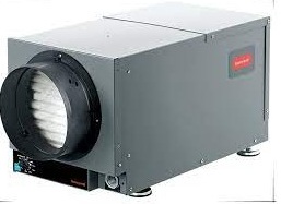

Installation Checklist
Included in This Box
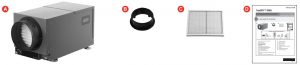

- A TrueDRY™ DR65 (1)
- B 8-in. duct collar (2)
- C MERV 11 Filter (1)
- D Installation Guide
Control Options (Sold separately)

- E1 Prestige IAQ Kit
- E2 True IAQ
- E3 H8908 Manual Dehumidistat
- E4 VisionPRO or Prestige Thermostat
- E5 HumidiPRO Digital Control
Tools Required (Not Supplied)
- 3/8-in. hex drive
- Drill or duct cutting tool
- Wire stripper/cutter
- Standard screwdriver
- T20 Torx screwdriver
- Duct tape
- 8-in. round duct and starter collar
- 18-22 gauge, 5 conductor thermostat wire
- /2-in. diameter drain line (8 ft.)
- 1/2-in. drain clamps (2)
- 3/4-in. male NPT drain outlet
Options
- 1/2-in. drain p-trap (may be required by local code)
- Drain pan
- Float switch or water sensor (normally closed)
Warning: Installation must be performed by a qualified service technician and must comply with local codes.
Remove power to the device before installing or servicing the device. Failure to connect the device according to these instructions may result in damage to the device or the controls
About the TrueDRY™ DR65 Dehumidifier

The Honeywell TrueDRY DR65 ensures the home is maintained at proper humidity levels through its high performance and efficiency.
Benefits
- Removes up to 65 pints (30.8 l) of water per day from the indoor air.
- Built-in humidity control requires no additional wiring to an external control. Just plug in and go! Choice of external control options also available for centrally ducted control.
- Energy Star rated.
- Built-in transfromer circuit breaker.
Maintaining Ideal Humidity
Dew points and relative humidity (RH) affect the way your body senses heat. Higher humidity levels cause the air to feel much hotter than the actual temperature. When maintained properly, you can run your cooling equipment less because dehumidified air feels cooler.
WHAT THE AIR FEELS LIKE HOW HOT THE HEAT-HUMIDITY COMBINATION MAKES IT FEEL. EXAMPLE: AIR AT 90ºF WITH 50% RH FEELS LIKE 96ºF TO THE HUMAN BODY!

Ideal humidity is defined by industry experts* as being between 40-60% on an average annual basis. When indoor humidity exceeds 60%, the home is more susceptible to mold and mildew growth. TrueDRY DR65 safeguards against excessive humidity in the home year-round..
*American Society of Heating, Refrigerating and Air Conditioning Engineers (ASHRAE).

Setting the Controls
BUILT-IN HUMIDITY CONTROL: An intuitive ‘set and forget’ humidistat is built into the TrueDRY DR65 to set the humidity level right on the device. Optional external control wiring is also available. If an external dehumidistat is used, the on-board dehumidification control must be set to the Off position.

Control Options
The TrueDRY™ DR65 may be used with one of the following external controls:
Prestige™ IAQ Kit

- Controls both heating/cooling and ventilation.
- Wireless sensor for displaying outdoor temperature and humidity.
- Advanced ventilation programming includes economizing and extreme condition shutdown.
- Maintenance and service reminders.
- High definition color display.
- RedLINK™ Wireless technology
TrueIAQ Digital Control

- Automatic adjustments maintain fresh air in home.
- Sensor for displaying outdoor temperature and humidity.
- Advanced ventilation programming includes economizing and extreme
condition shutdown. - Maintenance and service reminders.
- Controls other indoor air quality equipment.
VisionPRO™ or Prestige™

- Controls both heating/cooling and ventilation.
- Wireless sensor for displaying outdoor temperature and humidity.
- Ventilation programming for time of day or Ashrae standards.
- Optional ventilation lockouts for high/low temp or humidity conditions when C7089R1013 wireless outdoor sensor is used.
- Wi-Fi™ or RedLINK™ Wireless technology
Manual Dehumidistat and Automatic Ventilation Controls

- Manual humidity control with intuitive comfort settings.
- Automatic W8150 ventilation control to ASHRAE standard, or for continuous operation.
HumidiPRO Digital Control

- Manual dehumidification control
- Dehumidifier compressor protection
- RH% and outdoor temperature calibration
- Adjustable high and low range stops (10-90%)
Specifications
Install TrueDRY DR65 according to National Electric Codes.
| Dry-Bulb Temp | Intake Humidity | Capacity (Pints/Day) |
| 80°F (26.7°C) | 60% RH | 68 |
| 70°F (21.1°C) | 60% RH | 47 |
| 60°F (15.6°C) | 60% RH | 34 |
| Home Size (square ft) @ 8 ft ceiling | Dehumidifier Capacity Required to Maintain Desired Indoor RH* | ||
| 60% RH Indoor (pints/day) | 50% RH Indoor (pints/day) | 40% RH Indoor (pints/day) | |
| 2080 | 49–54 | 55–58 | 71–78 |
| 2600 | 61–68 | 65–72 | 90–97 |
| 3120 | 75–82 | 79–86 | 95–110 |
Based on extreme climates where outdoor humidity is 70-90% RH. For less extreme climates, larger homes can be adequately served with less capacity. Actual requirements may vary.
Dimensions in inches and (mm):

Product weight: 55 lb (25 kg)
Shipping weight: 65 lb (30 kg)
Shipping dimensions: 17 ¼ in. H x 15 ½ in. W x 31 ½ in. L
Media Filter: MERV 11, 9 in. H x 11 in. W x 1 in. D
Drain connection: 3/4-in. threaded female NPT connection.
Duct connections: 8-in. round inlet and outlet. ABS plastic, compatible for connection to rigid or flexible ducting with sheet metal screws and/or tape.
Cabinet: 18 gauge galvanized steel powder-coat painted.
Insulation: R value 1
Compressor: Rotary-style, 5.8 KBTU
Refrigerant: R-410A, 15 oz.
Operating Temp Range (outside cabinet): 34ºF to 135ºF (1.1ºC to 57.2ºC)
Operating Humidity Range: 0-99% RH
Airflow versus external static pressure (0–1 in. water pressure) with collars attached
| 0 in. | 160 CFM |
| 0.2 in. | 140 CFM |
| 0.4 in. | 120 CFM |
| 0.6 in. | 100 CFM |
Input ratings
- Electrical input voltage: 120 VAC, 60 Hz nominal
- Input current: 5.2 A
Output ratings
- Power transformer to R/C terminals: 24 VAC, 0.85 A
- Energy Performance: 2.22 liters (4.7 pints) per kilowatt hour (KWH).
Standards and approval body requirements
ETL Tested per standard UL 60335-2-40 ducted dehumidifier. ENERGY STAR rated.
Install to Fit Your Application

Flex duct is recommended in connecting to the TrueDRY DR65 collars to reduce vibration noise.
Duct Sizing: Use minimum 8-in. diameter round for duct lengths up to 25 ft. Minimum 10-in. required for lengths longer than 25 ft. Duct branches from the main inlet/ exhaust should be minimum 8-in. round for 2-3 branches, and 8-in. round or larger for 4 branches or more.
Isolated Areas: Effective dehumidification may require ducting to isolated or stagnant air flow areas.
Electrical requirements:
115 VAC outlet. Ground fault interrupter (GFI) recommended.

Dedicated Return to Main Supply

Ideal when….
- Access to a dedicated central return for TrueDRY DR65 is available.
- Combined with A/C operation; requires backdraft damper on the exhaust port to minimize backdraft when TrueDRY DR65 is not on but A/C is.
- Providing dry air to a specific area with an optional 20% open gravity damper on TrueDRY DR65 supply.
Main Return to Main Supply

Ideal when…
- Running TrueDRY DR65 when not running A/C. Requires damper on the exhaust port to minimize backdraft when TrueDRY DR65 is not on but A/C is.
- Access to a dedicated central return for TrueDRY DR65 is not available.
- System fan should run with dehumidifier for best results.
Main Return to Main Return

Ideal when…
- Running TrueDRY DR65 with A/C operation.
- System fan must run with dehumidifier.
- Minimizing discharge air temperature (DAT) increase is preferred.
- Access to a dedicated central return for TrueDRY DR65 is not available.
Dedicated Return to Dedicated Supply

Ideal when…
- TrueDRY DR65 will not be ducted to a forced air HVAC system.
Plumbing

Attach 3/4-in. male NPT drain nozzle.
Connect 1/2-in. drain tube to male connection drain outlet.
Secure drain tube to connector with hose clamp.
Run drain hose continuously downhill to an approved drain or condensate pump.
The drain line must include a water trap to prevent air from entering or exiting the dehumidifier.
Terminal Description
CAUTION: Low voltage hazard.
Can cause equipment damage.
Disconnect HVAC equipment before beginning installation.
Two wiring terminal blocks are located on the exhaust end of the TrueDRY unit.
The six terminals for the left hand terminal block are:

NOTE: The outer screws on each terminal block secure the block to the chassis. They are not used for wiring.
FLOAT (2):External low-voltage water sensor or float switch
DHUM: Compressor and fan operation for dehumidification
R: DR65 24V output FA
FAN: Fan activation only for ventilation
C: DR65 24V output
External 24V devices can be powered from R and C terminals (20VA max.)
The right hand terminal block in the above figure is used only for interlocking a TrueDry DR65 with an equipment fan. The three terminals are:
- Gt: Fan operation from thermostat
- Rf: 24V from equipment fan
- Gf: Fan operation from equipment fan
Wiring
Wire the TrueDRY DR65 according to the diagram that applies to your desired operation.
Follow this diagram for ducted operation with the onboard dehumidistat

Follow this diagram if using the HumidiPro Digital Humidity Controller.

Follow this diagram if using the Prestige™ thermostat.

Follow this diagram if using an external manual dehumidistat.

Follow this diagram for ducted operation with external ventilation control.

Follow this diagram if using TrueDRY DR65 with a powered dehumidistat such as TrueIAQ (DG115EZIAQ).

- IF A THERMOSTAT OTHER THAN A TH5110, TH5220, TH5320, TH6110, TH6220, TH6320, TH8110, TH8320, OR TH8321 IS USED, A RELAY MAY BE REQUIRED TO ISOLATE THE G WIRE
- PROGRAM ISU SETTING 60 TO Ø TO FORCE SYSTEM FAN ON WITH DEHUMIDIFICATION CALL.
Follow this diagram if using TrueDRY DR65 with a Prestige IAQ or VisionPro IAQ.

Circuit Breaker
To prevent damage to the 24 volt control transformer, the DR65A2000 comes with a resettable circuit breaker. Check wiring for any electrical short and repair before resetting breaker. Resetting the circuit breaker without correcting the electrical short may result in transformer damage. Be sure to check the electrical schematics in this manual or inside the access panel of the DR65A2000 before making any control connections. The reset button for the circuit breaker can be found on the back of the unit.
Checkout
Apply power to TrueDRY DR65. Turn the humidity control to a low RH% level to initiate a dehumidification call. Confirm that the TrueDRY DR65 compressor and fan turn on. The furnace blower will also turn on to circulate air. This will take up to two minutes. Be sure to turn the control to the desired RH% or to Off when checkout is complete. Turning the humidity control to Off will turn TrueDRY DR65 off.
Cleaning
On an annual basis, maintenance is required to ensure TrueDRY runs at peak efficiency
- Unplug TrueDRY DR65 before beginning service. Press down on the quick-release button and lift the duct collar.
- Remove duct collar to access filter.
- with new filter.
- Check the drain connection and drain line to ensure it is clear of debris and sludge. Ensure all hose connections are secure once maintenance of the drain lines is complete.
- When service is complete, initiate a call for dehumidification and check that the compressor and fan activate. If using the VisionPRO IAQ or TrueIAQ controls, reset maintenance reminders.


Horizontal to Vertical Conversion
- Remove the six screws attached to 1 the wiring side of the duct collar
- Remove the duct collar.
- Rotate the collar to the position shown in the figure and place it back on the cabinet.
- Reattach the duct collar using the six screws.


Technical Description

TrueDRY DR65 uses a refrigeration system similar to an air conditioner to remove heat and moisture from incoming air and add heat to the air that is discharged. Hot, highpressure refrigerant gas is routed from the compressor to the condenser coil. The refrigerant is cooled and condensed by giving up its heat to the air that is about to be discharged from the unit. The refrigerant liquid then passes through a filter drier and capillary tubing which causes the refrigerant pressure and temperature to drop. It next enters the evaporator coil where it absorbs heat from the incoming air and evaporates. The evaporator operates in a flooded condition, which means that all the evaporator tubes contain liquid refrigerant during normal operation. A flooded evaporator should maintain nearly constant pressure and temperature across the entire coil, from inlet to outlet.
Troubleshooting
Troubleshooting videos are available on Honeywell’s CPRO YouTube channel playlist.
CAUTION: Servicing the TrueDRY DR65 with its high pressure refrigerant system and high voltage circuitry presents a health hazard which could result in death, serious bodily injury, and/ or property damage. Service should only be performed by a qualified service technician.
| Problem | Recommended Troubleshooting Steps |
| No dehumidification. Neither fan nor compressor run and the ventilation timer is OFF. | 1. Unit unplugged or no power to outlet. 2. Humidity control set too high or defective. 3. Loose connection in internal or control wiring. 4. Defective Compressor relay. 5. Defective control transformer. 6. Optional Condensate Pump Safety Switch open. |
| No dehumidification. Compressor does not run but fan runs when there is a call for dehumidification and the ventilation control is OFF. | 1. Defective compressor run capacitor. 2. Bad connection in compressor circuit. 3. Defective compressor overload. 4. Defective compressor. 5. Defrost thermostat open. 6. Optional Condensate Pump Safety Switch open. |
| Fan runs when there is a call for dehumidification and the ventilation control is OFF, but the compressor cycles on and off too frequently. | 1. Low ambient temperature and/or humidity causing unit to cycle through defrost mode. 2. Defective compressor overload. 3. Defective compressor. 4. Defrost thermostat defective. 5. Dirty air filter(s) or airflow restricted. 6. Low refrigerant charge, causing defrost control to cycle. 7. Bad connection in compressor circuit. Fan does not run with fan switch in either position. |
| Problem | Recommended Troubleshooting Steps |
| Fan does not run with ventilation activated. Compressor runs briefly but cycles on & off with humidity control turned to ON. |
1. Loose connection in fan circuit. 2. Obstruction prevents fan rotation. 3. Defective fan. 4. Defective fan relay. 5. Defective fan capacitor. |
| Evaporator coil frosted continuously, low de-humidifying capacity. | 1. Defrost thermostat loose or defective. 2. Low refrigerant charge. 3. Dirty air filter(s) or airflow restricted. |
| Unit not providing ventilation. | 1. Check control wire connections (check connections at fresh air damper also). 2. Defective fresh air damper. 3. Dirty air intake. Clean outside intake hood. |
| Unit removes some water, but not as much as expected. | 1. Air temperature and/or humidity have dropped. 2. Humidity meter and or thermometer used are out of calibration. 3. Unit has entered defrost cycle. 4. Dirty air filter. 5. Defective defrost thermostat. 6. Low refrigerant charge. 7. Air leak such as loose cover or ducting leaks. 8. Defective compressor. 9. Restrictive ducting. 10. Optional Condensate Pump Safety Switch open. |
| Unit Test to determine problem: | 1. Detach field control wiring connections from main unit. 2. Connect the R and FAN contacts from the main unit together; only the impeller fan should run. Disconnect the wires. 3. Connect the R and DHUM contacts from the main unit together; the compressor and impeller fan should run. 4. If these tests work, the main unit is working properly. You should check the control panel and field control wiring for problems next. 5. Remove the control panel from the mounting box and detach it from the field installed control wiring. Connect the blue, yellow, and green wires from the control panel directly to the corresponding colored pigtails on the main unit. Leave the violet, white, and red wires disconnected! 6. Turn on the humidity control. The compressor and impeller fan should run. 7. If these tests work, the problem is most likely in the field control wiring. |
Refrigerant Charging
If the refrigerant charge is lost due to service or a leak, a new charge must be accurately weighed in. If any of the old charge is left in the system, it must be recovered before weighing in the new charge. Refer to the unit nameplate for the correct charge weight and refrigerant type.
Parts List
| Figure Reference | Base and Accessory Parts | Part Number |
| 1 | TrueDRY DR65 | DR65A2000/U |
| 2 | Motorized Ventilation Damper | EARD8TZ |
| 3 | 8 in. Bypass Damper | CPRD8 |
| Figure Reference | Replacement Parts | Part Number |
| 4 | Compressor Relay, 24 VAC, 30 A | 50049537-002 |
| 5 | Compressor Run Capacitor | 50049537-003 |
| 6 | 8″ Duct Collar | 50049537-004 |
| 7 | Fan Assembly | 50049537-006 |
| 8 | Capacitor – Fan | 50070204-001 |
| 9 | Fan Relay, SPDT, 24 VAC, 15A | 50035445-011 |
| 10 | Transformer 120/24 VAC, 40 VA | 50035445-013 |
| 11 | Defrost Thermostat | 50070204-002 |
| 12 | Filter | 50049537-005 |

5-Year Limited Warranty
Honeywell warrants this product to be free from defects in the workmanship or materials, under normal use and service, for a period of five (5) years from the date of purchase by the consumer. If at any time during the warranty period the product is determined to be defective or malfunctions, Honeywell shall repair or replace it (at Honeywell’s option.
If the product is defective,
- return it, with a bill of sale or other dated proof of purchase, to the place from which you purchased it; or
- call Honeywell Customer Care at 1-800-468-1502. Customer Care will make the determination whether the product should be returned to the following address: Honeywell Return Goods, Dock 4 MN10-3860, 1885 Douglas Dr. N., Golden Valley, MN 55422, or whether a replacement product can be sent to you. This warranty does not cover removal or reinstallation costs. This warranty shall not apply if it is shown by Honeywell that the defect or malfunction was caused by damage which occurred while the product was in the possession of a consumer
Honeywell’s sole responsibility shall be to repair or replace the product within the terms stated above. HONEYWELL SHALL NOT BE LIABLE FOR ANY LOSS OR DAMAGE OF ANY KIND, INCLUDING ANY INCIDENTAL OR CONSEQUENTIAL DAMAGES RESULTING, DIRECTLY OR INDIRECTLY, FROM ANY BREACH OF ANY WARRANTY, EXPRESS OR IMPLIED, OR ANY OTHER FAILURE OF THIS PRODUCT. Some states do not allow the exclusion or limitation of incidental or consequential damages, so this limitation may not apply to you.
THIS WARRANTY IS THE ONLY EXPRESS WARRANTY HONEYWELL MAKES ON THIS PRODUCT. THE DURATION OF ANY IMPLIED WARRANTIES, INCLUDING THE WARRANTIES OF MERCHANT ABILITY AND FITNESS FOR A PARTICULAR PURPOSE, IS HEREBY LIMITED TO THE FIVE-YEAR DURATION OF THIS WARRANTY. Some states do not allow limitations on how long an implied warranty lasts, so the above limitation may not apply to you.
This warranty gives you specific legal rights, and you may have other rights which vary from state to state. If you have any questions concerning this warranty, please write Honeywell Customer Relations, 1985 Douglas Dr, Golden Valley, MN 55422 or call 1-800-468-1502.
Home and Building Technologies
In the U.S.:
Honeywell 1985 Douglas Drive North Golden Valley, MN 55422
website: http://yourhome.honeywell.com