Honeywell Convertible Humidity Control H908A Instructions


Honeywell Convertible Humidity Control H908A

APPLICATION
This is a legacy product document supported by Resideo. It is no longer manufactured.
The H908A Convertible Humidity Control provides automatic low voltage control of humidifiers in central heating systems. The humidity control has a single pole, single throw, snap-acting, dust-proof switch and is designed for wall or surface duct mounting.
INSTALLATION
When Installing this Product…
- Read these instructions carefully. Failure to follow them could damage the product or cause a hazard-ous condition.
- Check the ratings given in the instructions and on the product to make sure the product is suitable for your application.
- Installer must be a trained, experienced service technician.
- After installation is complete, check out product operation as provided in these instructions.
CAUTION
Personal Injury Hazard.
Power supply can cause electrical shock. Disconnect power supply before beginning installation.
Location and Mounting
Wall Mounting
IMPORTANT
- Mount the control in an area with average room temperature and average relative humidity.
- The control can be mounted directly on the wall.
- Locate the control about 5 ft (1.5m) above the floor on an inside wall.
- Drill a 3/8 in. (10 mm) hole in the wall.
- Run low voltage wiring to the location and pull about 6 in. (152 mm) of wire through the hole.
- Plug the hole with nonflammable insulation to prevent drafts from affecting control operation.
- Unscrew the two baseplate screws and remove the control assembly.
- To assemble the control for wall mounting (see Fig. 1):
- Drill clearance hole in baseplate for low voltage wiring.
- Turn over the baseplate so the text faces the wall.
- Place the control assembly on the baseplate with the dial shaft facing toward you.
d - crew the two removed screws through the back of the baseplate to secure the control assembly.
- Position the baseplate horizontally over the wire and pull the wire through the hole.
- Use two of the 1 in. (25 mm) screws to secure the baseplate to the wall.
- Connect the wires to the terminals on the control assembly.
- Use one of the 3/8 in. (10 mm) screws to secure the cover to the control assembly
- Push the setpoint dial down onto the shaft.

Duct Mounting
IMPORTANT
If mounting near an elbow area, keep the control 6 in. (152 mm) upstream from the elbow so the element is exposed to the normal airflow (Fig. 2).
- Locate the control at least 8 in. (203 mm) upstream from the humidifier in the return air duct. See Fig. 2.
- Apply the template to the duct location.
NOTE: Make sure template is level before drilling holes. - Refer to the template, Fig. 3, and use the following steps to drill the control assembly opening, mounting holes and mount the gasket:
- Drill a 1/2 in. (13 mm) hole in the center of the template and use a tinsnips to enlarge the opening to the dotted line.
- Drill four 7/64 in. (3 mm) mounting holes.
- Remove the protective backing from the foam gasket and mount the gasket on the shaded area of the template.
IMPORTANT: Use 18- to 22-gauge wire for proper wiring. - Run a low voltage wire to the control and connect it to the two terminals. Tuck the excess wire into the recessed area on the back of the baseplate.
- Use sheet metal screws to secure the assembly to the duct through the mounting holes. See Fig. 4.
- Push the setpoint dial down onto the shaft.


WIRING
CAUTION
Personal Injury Hazard. Power supply can cause electrical shock and injury. Disconnect power supply before installation or servicing.
All wiring must comply with applicable local codes, ordinances and regulations.
IMPORTANT
- Select models of fan centers include humidifer taps so the current sensing relay or sail switch is not needed.
- If not using a current sensing relay or sail switch, the humidifier must be energized during blower motor cycles for proper operation.
- On multispeed blower applications, do not wire the high voltage side of the transformer to the same power source that services the furnace blower. Premature transformer burnout can occur.
- On HE360 fan powered humidifier models, only the two yellow wires are connected to the control. The remaining two red wires are only used with electronic humidity controls.
For wiring information, refer to the typical wiring diagrams in Fig. 5 through 8.


SETTINGS
Control Adjustment
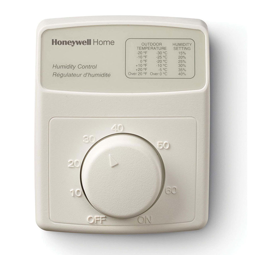
The humidity comfort range of a living space is 15 to 40 percent RH. If the outdoor temperature changes signifi-cantly, reset the humidity level on the control to assure maximum comfort. Choose the control setting using the table provided on the faceplate of the humidity control and match the dial setting to the outdoor temperature. The following table can also be used to adjust the control to the recommended setting.
CHECKOUT
NOTE: The furnace blower must be operating for the humidifier to work.
Turn up the control dial to the highest setting and make certain that the humidifier operates. Turn the control dial to Off and make certain the humidifier has shut off. Read the Control Adjustment section and set the control for automatic operation.
| At Outside Temperature | Recommended Control Setting | At Outside Temperature | Recommended Control Setting |
| -20°F (-30°C) | 15 | +10°F (-10°C) | 30 |
| -10°F (-25°C) | 20 | +20°F (-5°C) | 35 |
| 0°F (-20°C) | 25 | Above 20°F (0°C) | 40 |
NOTE: Some indoor activities such as cooking, showering and clothes drying can cause excessive levels of humidity and produce excessive moisture on windows or walls. If this condition persists for more than a few hours, set the control to the lowest setting to turn off the humidifier. If the condition does not improve, ventilate your home to remove the moisture.
Home and Building Control Honeywell Inc.
Honeywell Plaza
P.O. Box 524
Minneapolis, MN 55408-0524
Home and Building Control
Honeywell Limited-Honeywell Limitée 155 Gordon Baker Road
North York, Ontario
M2H 3N7
